


U-8MX3XPQ(A)
Panasonic U-8MX3XPQ(A), U-16MX3XPQ(A), U-10MX3XPQ(A), U-14MX3XPQ(A), U-12MX3XPQ(A) Installation Manual
...
U-5MX3XPQ
U-8MX3XPQ(A)
U-10MX3XPQ(A)
U-12MX3XPQ(A)
U-14MX3XPQ(A)
U-16MX3XPQ(A)
U-18MX3XPQ
U-20MX3XPQ
U-22MX3XPQ
U-24MX3XPQ
U-26MX3XPQ
U-28MX3XPQ
U-30MX3XPQ
U-32MX3XPQ
U-34MX3XPQ
U-36MX3XPQ
U-38MX3XPQ
U-40MX3XPQ
U-42MX3XPQ
U-44MX3XPQ
U-46MX3XPQ
U-48MX3XPQ
INSTALLATION MANUAL
URBAN MULTI AIR CONDITIONER

54
32
c
ab
d
A C
B
D
c
abe
f
abe
d
c
f
d
A C
B
D
a be
c
d
e
A C
B
D
c
abe
f
abe
d
f
d
A C
B
D
c
H
h
h
1
h
2
≥1500
1
3
5
4
2
2
(mm)
6
3
≥1000
≥1000
≥1000
≥1500
≥
1500
≥1
500
722-737
80
80
765
A
B
1245
6
7
3
7
1
6
1
2
4
5
3
5
3
3
2
1
5
3
3
1
3 3
4
4
4
4
9
4
4
5
7
7
5
5
2
5
5
5
5
6
2
6
9
2
2
6
6
8
2
2
1
1
2
2
2
1
2
2
5
1
A B
A
B
42 31
1
2
3
4
5
6
7
U-5MX3 U-8+10MX3 U-12~16MX3
U-5~16MX3 U-18~48MX3
10
11
8
12
9
14 15
13
L1 L2 L3 N
1
2
3
4
5
6
66
14
7
9
8
11
12
13
15
15
ABCF1F2F1F2Q1Q2 Q1Q2 Q1Q2
A1P
44
5
6
21 3
1
2
3
4
56
7
18
19
19
10
151415
14
12
13
13
9
8
16
9
11
10
11
1
2
3
4
5
6
7
17
8
12
20
18
18
1
2
1
2
5
3
3
3
3
5
5
5
7
5
4
4
4
4
4
6
A
B
F2 F2F1 F1A B C Q1 Q2
1
4
3
2
2
66
6
5
1
2
3
3
4
4
5
6
3
4
3
4
6
3
4
6
F2F1 F2F1
F2
F1 F2F1
F2
F1
2
1
A B C
ABCF1 F2 F1 F2 Q1 Q2
ABCF1 F1F2 F2 Q1 Q2
F1 F2 F1 F2 F1 F2
F1 F2 F1 F2 F1 F2
F1 F2 F1 F2 F1 F2
4
5
6
1 27
C/H SELECTOR
TO IN/D UNIT
TO OUT/D UNIT TO MULTI UNIT
A1P
3
8
9
11
10
12
14
13
15
U-5~16MX3
U-18~48MX3

16 17
2019
21
A
12 3 4
4
35 75 6
1
3
2
2322
1
2
2
1
1
2
345
12
13
14
15
16 17 18
51
7
10
32
9
66
66
7
4
11
8
66 66
66
77
9
8
4
11
66
1
10
32
66
66
18
TO IN/D
UNIT
F1 F2
DS1
1234
OFF
ON
O
U
T
I
N
F1 F2 F1 F2
F1 F2
1
A B C
A B C
1
DS1
1234
OFF
ON
O
U
T
I
N
1 2 3454
16
17
18
19 20
21
22
23
U-5~10MX3 U-12~16MX3
U-12~16MX3U-5~10MX3

U-5~48MX3
Urban Multi air conditioner
4PW16235-1C
Installation manual
1
C
ONTENTS
P
age
1. Introduction.................................................................................... 1
1.1. Combination..........................................................................................1
1.2. Standard supplied accessories .............................................................2
1.3. Optional accessories............................................................................. 2
1.4. Technical and Electrical specifications ..................................................2
2. Main components ..........................................................................2
3. Selection of location.......................................................................2
4. Inspecting and handling the unit.................................................... 3
5. Unpacking and placing the unit......................................................3
6. Refrigerant piping ..........................................................................4
6.1. Selection of piping material...................................................................4
6.2. Connecting the refrigerant piping..........................................................4
6.3. Example of connection.......................................................................... 7
6.4. Leak test and vacuum drying ................................................................9
6.5. Pipe insulation..................................................................................... 10
6.6. Additional refrigerant charge...............................................................10
7. Field wiring...................................................................................11
7.1. Internal wiring – Parts table................................................................. 11
7.2. Optional parts cool/heat selector......................................................... 12
7.3. Power circuit and cable requirements.................................................. 12
7.4. General................................................................................................13
7.5. Examples.............................................................................................13
8. Before operation .......................................................................... 16
8.1. Checks before initial start-up............................................................... 16
8.2. Test run ................................................................................................16
9. Caution for refrigerant leaks ........................................................ 17
1. I
NTRODUCTION
This installation manual concerns Urban Multi units of the Panasonic
MX3 series. These units are designed for outdoor installation and
used for cooling and heatpump applications. The MX3 series can be
combined from 6 main units and has nominal capacities ranging from
14.0 to 134 kW and nominal heating capacities ranging from 16.0 to
150 kW.
The MX3 units can be combined with Panasonic Urban Multi
indoor units for air conditioning purposes, and suitable for R-410A.
The present installation manual describes the procedures for
unpacking, installing and connecting the MX3 units. Installation of the
indoor units is not described in this manual. Always refer to the
installation manual supplied with these units for their installation.
1.1. Combination
The indoor units can be installed in the following range.
■
Always use appropriate indoor units compatible with R-410A.
To learn which models of indoor units are compatible with
R-410A, refer to the product catalogs.
■
Total capacity/quantity of indoor units
U-5~48MX3
Urban Multi air conditioner
Installation manual
READ THIS MANUAL ATTENTIVELY BEFORE STARTING
UP THE UNIT. DO NOT THROW IT AWAY. KEEP IT IN
YOUR FILES FOR FUTURE REFERENCE.
IMPROPER INSTALLATION OR ATTACHMENT OF
EQUIPMENT OR ACCESSORIES COULD RESULT IN
ELECTRIC SHOCK, SHORT-CIRCUIT, LEAKS, FIRE OR
OTHER DAMAGE TO THE EQUIPMENT. BE SURE ONLY
TO USE ACCESSORIES MADE BY PANASONIC WHICH
ARE SPECIFICALLY DESIGNED FOR USE WITH THE
EQUIPMENT AND HAVE THEM INSTALLED BY A
PROFESSIONAL.
IF UNSURE OF INSTALLATION PROCEDURES OR USE,
ALWAYS CONTACT YOUR DEALER FOR ADVICE AND
INFORMATION.
The refrigerant R-410A requires strict cautions for keeping
the system clean, dry and tight.
■
Clean and dry
Foreign materials (including mineral oils such as
SUNISO oil or moisture) should be prevented from
getting mixed into the system.
■
Tight
R-410A does not contain any chlorine, does not
destroy the ozone layer, and does not reduce the
earth's protection against harmful ultraviolet radiation.
R-410A can contribute slightly to the greenhouse
effect if it is released. Therefore we should take
special attention to check the tightness of the
installation.
Read "6. Refrigerant piping" on page 4 carefully and follow
these procedures correctly.
Since design pressure is 3.8 MPa or 38 bar (for R-407C
units: 3.3 MPa or 33 bar), pipes of larger wall thickness may
be required. Refer to paragraph "6.1. Selection of piping
material" on page 4.
Outdoor unit
Total capacity of
indoor units
Total quantity of
indoor units
U-5MX3
(*)
62.5~162.5
8
U-8MX3 (*)
100~260
13
U-10MX3 (*)
125~325
16
U-12MX3 (*)
150~390
19
U-14MX3 (*)
175~455
20
U-16MX3 (*)
200~520
20
U-18MX3
225~585
20
U-20MX3
250~650
20
U-22MX3
275~715
22
U-24MX3
300~780
32
U-26MX3
325~845
32
U-28MX3
350~910
32
U-30MX3
375~975
32
U-32MX3
400~1040
32
U-34MX3
425~1105
34
U-36MX3
450~1170
36
U-38MX3
475~1235
38
U-40MX3
500~1300
40
U-42MX3
525~1365
40
U-44MX3
550~1430
40
U-46MX3
575~1495
40
U-48MX3
600~1560
40
(*) = main unit

Installation manual
2
U-5~48MX3
Urban Multi air conditioner
4PW16235-1C
1.2. Standard supplied accessories
Refer to figure 22.
1.3. Optional accessories
To install the above outdoor units, the following optional parts are
also required.
■
Refrigerant branching kit (for R-410A only: Always use an
appropriate kit dedicated for your system.)
■
Outdoor unit multi connection piping kit (For R-410A only:
Always use an appropriate kit dedicated for your system.)
To select an optimum refrigerant branching kit, refer to "6. Refrigerant
piping" on page 4.
1.4. Technical and Electrical specifications
Refer to the Engineering Data Book for the complete list of
specifications.
2. M
AIN COMPONENTS
For main components and function of the main components, refer to
the Engineering Data Book.
3. S
ELECTION OF LOCATION
This unit, both indoor and outdoor, is suitable for installation in a
commercial and light industrial environment. If installed as a household appliance it could cause electromagnetic interference.
The inverter units should be installed in a location that meets the
following requirements:
1
The foundation is strong enough to support the weight of the unit
and the floor is flat to prevent vibration and noise generation.
2
The space around the unit is adequate for servicing and the
minimum space for air inlet and air outlet is available. (Refer to
figure 1 and choose one of the possibilities).
In case of an installation site where only the sides A+B have
obstacles, the wall heights have no influence on any indicated
service space dimensions.
3
There is no danger of fire due to leakage of inflammable gas.
4
Ensure that water cannot cause any damage to the location in
case it drips out the unit (e.g. in case of a blocked drain pipe).
5
The piping length between the outdoor unit and the indoor unit
may not exceed the allowable piping length. (Refer to
"6.3. Example of connection" on page 7)
6
Select the location of the unit in such a way that neither the
discharged air nor the sound generated by the unit disturb
anyone.
7
Make sure that the air inlet and outlet of the unit are not
positioned towards the main wind direction. Frontal wind will
disturb the operation of the unit. If necessary, use a windscreen
to block the wind.
8
Do not install or operate the unit on locations where air contains
high levels of salt, like e.g. in the vicinity of oceans. (Refer for
further information to the engineering databook).
U-5MX3
U-8~16MX3
Gas line piping (1) — 1
Gas line piping (2) — 1
Gas line piping (3) — 1
Installation manual
Operation manual
1
1
1
1
Additional refrigerant charge
label
11
1
Installation and operational manual
2
Accessory pipes
Refnet header
Refnet joint
CZ-P29HK12Q CZ-P20BK12Q
CZ-P64HK12Q CZ-P29BK12Q
CZ-P75HK12Q CZ-P64BK12Q
— CZ-P75BK12Q
Number of outdoor units connected
2 3
CZ-32PJ1PQ CZ-48PJ1PQ
A B C D
Sides along the installation site with obstacles
Suction side
U-5~48MX3
Urban Multi air conditioner
4PW16235-1C
Installation manual
3
4. I
NSPECTING AND HANDLING THE UNIT
At delivery, the package should be checked and any damage should
be reported immediately to the carrier claims agent.
When handling the unit, take into account the following:
1
Fragile, handle the unit with care.
Keep the unit upright in order to avoid compressor damage.
2
Choose on beforehand the path along which the unit is to be
brought in.
3
Lift the unit preferably with a crane and 2 belts of at least 8 m
long.
4
When lifting the unit with a crane, always use protectors to
prevent belt damage and pay attention to the position of the
unit’s centre of gravity.
5
Bring the unit as close to its final installation position in its
original package to prevent damage during transport. (See
figure 3)
5. U
NPACKING AND PLACING THE UNIT
■
Remove the four screws fixing the unit to the pallet.
■
Make sure the unit is installed level on a sufficiently strong base
to prevent vibration and noise.
■
Fasten the unit in place using four anchor bolts M12.
■
Make sure the base under the unit is extended more than
765 mm behind the unit.
■
The unit must be installed on a solid longitudinal foundation
(steelbeam frame or concrete) as indicated in figure 4.
PRECAUTION
Block all gaps in the holes for passing out piping and wiring using
sealing material (field supply). (Small animals may enter the
machine.)
Example: passing piping out through the front
■
The equipment described in this manual may cause
electronic noise generated from radio-frequency
energy. The equipment complies to specifications that
are designed to provide reasonable protection against
such interference. However, there is no guarantee that
interference will not occur in a particular installation.
It is therefore recommended to install the equipment and
electric wires keeping proper distances away from stereo
equipment, personal computers, etc... (See figure 2).
In extreme circumstances you should keep distances of
3 m or more and use conduit tubes for power and
transmission lines.
■
In heavy snowfall areas, select an installation site
where snow will not affect operation of the unit.
■
The refrigerant R-410A itself is nontoxic,
nonflammable and is safe. If the refrigerant should
leak however, its concentration may exceed the
allowable limit depending on room size. Due to this it
could be necessary to take measures against
leakage. Refer to the chapter "9. Caution for
refrigerant leaks" on page 17.
■
Do not install in the following locations.
• Locations where sulfurous acids and other corrosive
gases may be present in the atmosphere.
Copper piping and soldered joints may corrode,
causing refrigerant to leak.
• Locations where equipment that produces electromagnetic waves is found.
The electromagnetic waves may cause the control
system to malfunction, preventing normal operation.
• Locations where flammable gases may leak, where
thinner, gasoline, and other volatile substances are
handled, or where carbon dust and other incendiary
substances are found in the atmosphere.
Leaked gas may accumulate around the unit, causing
an explosion.
1 Personal computer or radio
2 Fuse
3 Earth leak detector
4 Remote controller
5 Cool/heat selector
6 Indoor unit
1
Packaging material
2
Opening (large)
3
Belt sling
4
Opening (small)(40x30)
5
Protector
Model A B
U-5MX3 635 497
U-8+10MX3 930 792
U-12~16MX3 1240 1102
Do not use stands to support the corners. (See figure 5)
■
Prepare a water drainage channel around the
foundation to drain waste water from around the unit.
■
If the unit is to be installed on a roof, check the
strength of the roof and its drainage facilities first.
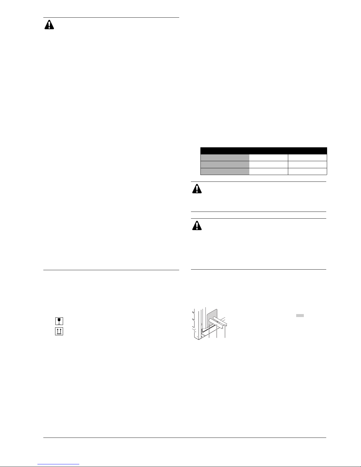
■
If the unit is to be installed on a frame, install the
waterproofing board within a distance of 150 mm
under the unit in order to prevent infiltration of water
coming from under the unit.
X Not allowed
O Allowed
123
1 Plug the areas marked with “ “.
(When the piping is routed from the front
panel.)
2 Gas side piping
3 Liquid side piping

Installation manual
4
U-5~48MX3
Urban Multi air conditioner
4PW16235-1C
6. R
EFRIGERANT PIPING
6.1. Selection of piping material
1.
Foreign materials inside pipes (including oils for fabrication) must be
30 mg/10 m or less.
2.
Use the following material specification for refrigerant piping:
■
Size: determine the proper size referring to chapter
"6.3. Example of connection" on page 7.
■
Construction material: phosphoric acid deoxidized seamless
copper for refrigerant.
■
Temper grade: use piping with temper grade in function of the
pipe diameter as listed in below table.
■
The pipe thickness of the refrigerant piping should comply
with relevant local and national regulations. The minimal pipe
thickness for R-410A piping must be in accordance with the
table below.
3.
Make sure to use the particular branches of piping that have been
selected referring to chapter "6.3. Example of connection" on
page 7.
4.
In case the required pipe sizes (inch sizes) are not available, it is also
allowed to use other diameters (mm sizes), taken the following into
account:
■
select the pipe size nearest to the required size.
■
use the suitable adapters for the change-over from inch to
mm pipes (field supply).
6.2. Connecting the refrigerant piping
1
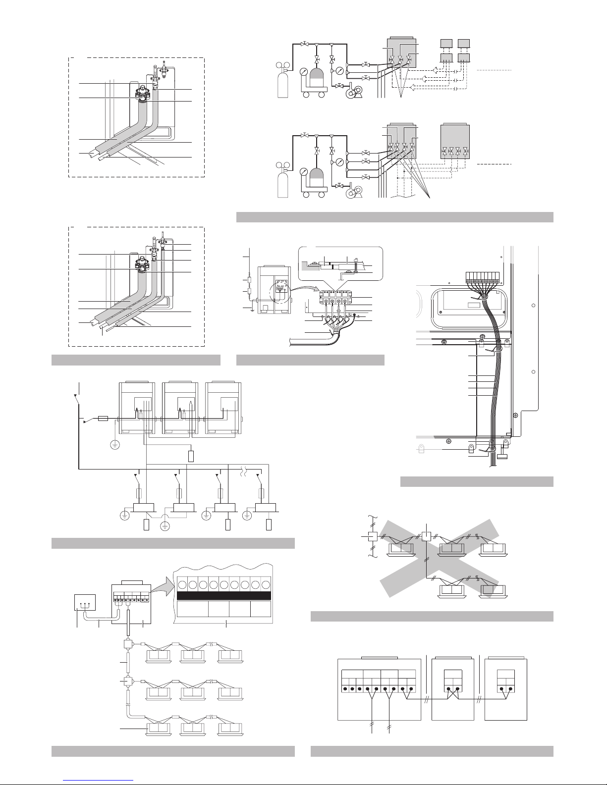
Installation of refrigerant piping is possible as front connection or
side connection (when taken out from the bottom) as shown in
the figure.
[One outdoor unit installed: In case of U-5~16MX3]
■
Front connection:
Remove the stop valve cover to connect. (See figure 6)
■
Side (bottom) connection:
Remove the knock holes on the bottom frame and route the piping
under the bottom frame. (See figure 6)
[When multiple outdoor units are installed: In case of
U-18~48MX3]
To connect the piping between outdoor units, an optional piping kit
(multi connection piping kit) is always required. When installing the
piping, follow the instructions in the installation manual that comes
with the kit.
■ Front connection:
Remove the stop valve cover to connect. (See figure 6)
■ Side (bottom) connection:
Remove the knock holes on the bottom frame and route the piping
under the bottom frame. (See figure 6)
Use R-410A to add refrigerant.
All field piping must be installed by a licensed refrigeration
technician and must comply with relevant local and
national regulations.
CAUTION TO BE TAKEN WHEN BRAZING
REFRIGERANT PIPING
Do not use flux when brazing copper-to-copper refrigerant
piping. (Particularly for the HFC refrigerant piping)
Therefore, use the phosphor copper brazing filler metal
(BCuP) which does not require flux.
Flux has extremely harmful influence on refrigerant piping
systems. For instance, if the chlorine based flux is used, it
will cause pipe corrosion or, in particular, if the flux
contains fluorine, it will damage the refrigerant oil.
Be sure to perform a nitrogen blow when brazing.
(Brazing without performing nitrogen replacement or
releasing nitrogen into the piping will create large
quantities of oxidized film on the inside of the pipes,
adversely affecting valves and compressors in the
refrigerating system and preventing normal operation.)
NOTE
Installation tools:
Make sure to use installation tools (gauge manifold
charge hose, etc.) that are exclusively used for R-410A
installations to withstand the pressure and to prevent
foreign materials (e.g. mineral oils such as SUNISO
and moisture) from mixing into the system.
(The screw specifications differ for R-410A and
R-407C.)
Vacuum pump (use a 2-stage vacuum pump with a
non-return valve):
■ Make sure the pump oil does not flow oppositely
into the system while the pump is not working.
Pipe Ø Temper grade of piping material
≤15.9 O
≥19.1 1/2H
O = Annealed
1/2H = Half hard
Pipe Ø
Minimal thickness
t (mm)
Pipe Ø
Minimal thickness
t (mm)
6.4 0.80 22.2 0.80
9.5 0.80 28.6 0.99
12.7 0.80 34.9 1.21
15.9 0.99 41.3 1.43
19.1 0.80
1 Left-side connection
2 Front connection
3 Right-side connection
A Front connection
Remove the stop valve cover to connect.
B Side (bottom) connection:
Remove the knock holes on the bottom frame and route the piping
under the bottom frame
1 Flange (or flare nut in case of models U-5MX3-type)
2 Gas side pipe (1)(2)(3) supplied with the unit. (In case of U-5MX3-
type, field supply.)
3 Oil-equalizing piping stop valve (except U-5MX3 and
U-8+10MX3). No piping work is needed
4 Flare nut
5 Brazing (Except U-5MX3)
6 Liquid side piping (field supply)
7 Knockout hole (use a hammer)
8 Gas side piping (field supply)
9 Oil-equalizing piping (field supply)
12 3
 Loading...