


 Loading...
Panasonic Solutions Company
Studio System 300
Basic Installation Guide
1

Panasonic Solutions Company
Table Of Contents
|
|
DESCRIPTION |
Page |
DESCRIPTION |
Page |
||||||
|
|
Important Power OFF |
|
3 |
|
Block Diagram |
25 |
|
|||
|
|
|
|
|
|
|
|
|
|
|
|
|
|
Introduction |
|
4 |
|
GPI Menu |
26 |
||||
|
|||||||||||
|
|
|
|
|
|
|
|
|
|
|
|
|
|
Base Station AG-BS300 |
|
5 |
|
Battery Menu HPX370 and HPX500 |
27 |
|
|||
|
|
Camera Adaptor AG-CA300 |
|
|
6 |
|
Battery Menu HDX900 though HPX3700 |
|
28 |
||
|
|
Battery Mount |
|
7 |
|
GenLock Menu Settings |
29 |
||||
|
|
|
|
|
|
|
|
|
|
|
|
|
|
ROP AG-EC4 |
|
|
8 |
|
SDI Switch and Menu settings |
30 |
|||
|
|
|
|
|
|
|
|
|
|
||
|
|
ROP AJ-RC10 |
|
|
9 |
|
RTS Intercom Connections |
31 |
|||
|
|
|
|
|
|
|
|
|
|
|
|
|
|
View Finder Interface AG-YA500 |
10 |
Clear-Com Intercom Support |
32 |
||||||
|
|
|
|
|
|
|
|
|
|
|
|
|
|
Studio Cable 300 |
11-12 |
|
HPX500 DA Setup |
33-34 |
|
||||
|
|
|
|
|
|
|
35-36 |
|
|||
|
|
ROP Cable 10M |
|
13 |
|
Fiber Option |
|
||||
|
|
ROP Cable 9” |
|
14 |
|
Trouble Shooting |
37-38 |
|
|||
|
|
GenLock and SDI |
|
15 |
|
Accessory Parts List |
39 |
||||
|
|
|
|
|
|
|
|
|
|
|
|
|
|
VF GPI/Return Cable |
|
16 |
|
Cable Technical Reference |
40-44 |
|
|||
|
|||||||||||
|
|
Lens Return Cable |
17-18 |
|
AV-HS400A Tally Connection |
45 |
|||||
|
|
|
|
|
|
|
|
|
|||
|
|
Lens Return with Tally Option |
|
19 |
|
AV-HS450 Tally Connection |
46 |
||||
|
|
|
|
|
|
|
|
|
|
||
|
|
Tally Trigger Cable |
|
|
20 |
|
Prompter Connection |
47 |
|||
|
|
|
|
|
|
|
|
|
|||
|
|
Power Tap Mentor Power Cable |
|
|
21 |
|
Replacement Parts |
48 |
|||
|
|
|
|
|
|
|
|
|
|||
|
|
Power Tap Multi Adaptor |
|
22 |
|
Support Hot Line |
49 |
||||
|
|
|
|
|
|
|
|
|
|||
|
|
VF Cable |
|
23 |
|
Notes |
50 |
||||
|
|
AJA Power Cable |
|
24 |
|
|
|
. |
|
||
2

Panasonic Solutions Company
IMPORTANT
POWER OFF
Please make sure the power is turned OFF on all equipment before making any connections!
3

Panasonic Solutions Company
Section 1 - Studio System 300
Introduction
The Studio System 300 will work with the following cameras:
AG-HPX300, AGHPX370, AGHPX500, AJ-HDX900, AJ-HPX2000, AJ-HPX2700, AJ-HPX3000, AJ-HPX3100 and AJ-HPX3700.
Before installation of the Studio System 300, Lets review all of the components and its function.
4

Panasonic Solutions Company
Section 1 - Studio System 300
Base Station – AG-BS300
Front
Back
The Base Station AG-BS300 is the heart of the system.
It provides the following: Power to the Camera*, Tally, Intercom, GenLock, Return Video (SDI or Video or Both) and ROP Control.
*Does not provide power under the following 3 conditions:
1. |
The Base Station is powered using 12 Volts DC. |
|
2. |
A Fiber Option is used in place of the studio cable. |
|
3. |
Using 2 RG6 Type BNC Cables Only (no power cable). |
5 |

Panasonic Solutions Company
Section 1- Studio System 300
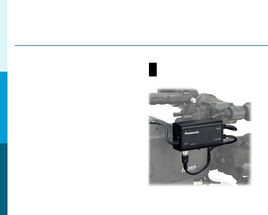
Camera Adaptor – AG-CA300
|
Back |
Right |
Left |
|
|
|
|
|
|
|
|
|
|
|
|
The Camera Adaptor AG-CA300 attaches to the Anton Bauer Gold Mount on the back of the Camera. It does the following:
Connects to the GenLock, SDI Out, ROP, Provides Intercom, Return Video (SDI or Video or Both), GPI, Tally, Tally Out Trigger
and Power. It only needs 3 connections to connect with the Base Station 6 (1 Power and 2 SDI).

Panasonic Solutions Company
Section 1- Studio System 300
Battery Mount Option – Anton Bauer Gold Mount
If using a fiber option to run a cable length more than 100 M, |
|
power must be provided locally at the camera head. The supplied |
|
Anton Bauer Gold Battery Mount must be used. Do Not Try to power |
|
the camera using the 4 Pin XLR 12V input. The system can only be |
|
powered though the battery mount. |
7 |
|

Panasonic Solutions Company
Section 1- Studio System 300
Remote Operation Panel (ROP) AG-EC4
|
Front |
Back |
|
|
|
The Remote Operation Panel (ROP) AG-EC4 is a simple control |
|
panel that works with all system supported cameras. |
|
This includes the following:HPX300, HPX370, HPX500, HDX900, |
|
HPX2000, HPX2700, HPX3000, HPX3100 and HPX3700. |
8 |
Panasonic Solutions Company
Section 1- Studio System 300
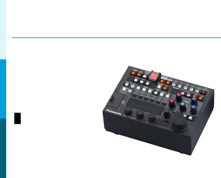
Optional Remote Operation Panel AJ-RC10
Not Recommended for AG-HPX300, AG-HPX370 or AG-HPX500
The AJ-RC10 is a full featured |
|
Remote Operation Panel. |
|
It is recommended for the |
|
Cameras that offer more |
|
control options. Example: |
|
Knee and Slope Controls, |
|
Master Gama, Etc. |
|
It is not recommended for |
|
the HPX300, HPX370 or HPX500 |
|
as they are better suited to use the AG-EC4. |
|
Cameras that can take advantage of the AJ-RC10: |
|
HDX900, HPX2000, HPX2700, HPX3000, HPX3100 and HPX3700 |
9 |
|
Panasonic Solutions Company
Section 1- Studio System 300
View Finder Interface Box– AG-YA500
Not Available for AG-HPX300 or AG-HPX370
The AG-YA500 VF Interface Box allows Return Video and Tally to be sent to the View Finder. This option is usually used when the camera is in a hand held configuration and or no on board Monitor is present.
10
Panasonic Solutions Company
Section 2 – Cable Identification
Studio 300 Cable
Part #’s
Studio300/100
Studio300/50
Studio300/25
The Studio 300 Cable connects the Camera Adaptor AG-CA300 to the Base Station AG-BS300.
It is available in lengths of 25, 50 or 100 Meters.
It contains a DC Power Cable and 2 SDI cables.
The Maximum Distance that can be used is 100 Meters.
For longer lengths, a Fiber Option is Recommended
(Explained later in this guide).
Cable Labels 11
Cable Labels

Panasonic Solutions Company
Section 2 – Cable Identification
Studio300 Cable
To increase cable reliability, please loop the studio cable through the strain relieve and secure with the supplied cable
strap as shown.
Cable Strap
In order to make the BNC Connection |
|
easier to attach to the AG-CA300, use the |
|
2 right angle BNC adaptors supplied with |
|
the Studio Cable. |
Strain Relieve Clamp |
|
12 |

Panasonic Solutions Company
Section 2 – Cable Identification
10M ROP Cable
The 10 Meter ROP Cable Connects the AG-EC4 (or AJ-RC10) to the Base Station AG-BS300 Remote In.
It is also available in 50 Meter lengths.
AG-BS300
AG-EC4
13

Panasonic Solutions Company
Section 2 – Cable Identification
9” ROP Cable
The 9” ROP Cable Connects the Camera Adaptor AG-CA300 Remote to the Camera Remote.
This Cable Must Be connected for the system to work.
The connection is very delicate so please handle with extreme care and make sure all power is off.
14
Panasonic Solutions Company
Section 2 – Cable Identification
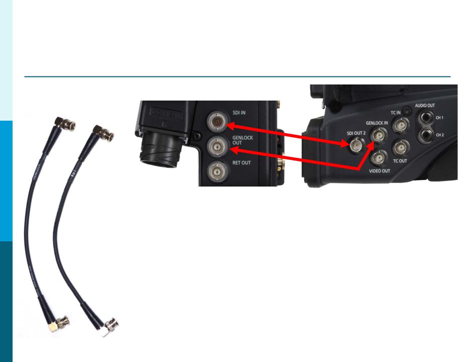
GENLOCK and SDI
These 2 short BNC cables connect:
1.AG-CA300 Camera Adaptor GenLock Out to the Camera GenLock In.
2.AG-CA300 SDI in to the Camera SDI Out.
Note: When connecting to the HPX300, HPX370 or HPX500, these cameras will automatically GenLock when the GenLock Cable is connected. However, the HDX900, HPX2000, HPX2700, HPX3000, HPX3100 and HPX3700 must be manually set to External GenLock in the
System Menu. Failure to turn this menu item on will
result in NO ROP control. See Page 29 for Menu Settings. 15
Loading...