


Digital Photo Printer
Operating Instructions
Model No.
SV-AP10E/EN/B
(For UK Customers Only)
Before use, please read these instructions completely.
Please retain this manual for future reference.
VQT0B56

Information for Your Safety
WARNING
TO REDUCE THE RISK OF FIRE OR SHOCK
HAZARD AND ANNOYING INTERFERENCE, USE
ONLY THE RECOMMENDED ACCESSORIES AND
DO NOT EXPOSE THIS EQUIPMENT TO RAIN OR
MOISTURE. DO NOT REMOVE THE COVER (OR
BACK); THERE ARE NOT USER SERVICEABLE
PARTS INSIDE. REFER SERVICING TO QUALIFIED
SERVICE PERSONNEL.
≥As this equipment gets hot during use, operate it in a
well-ventilated place; do not install this equipment in a
confined space such as a book case or similar unit.
≥Do not open the Ink Cassette Side Cover while
printing is in progress. Your fingers could be pinched
between the thermal head arms and the Ink Cassette.
IMPORTANT
Please respect all copyrights.
Whatever you have recorded and created can be used
for your personal entertainment only. Under
copyright laws, other materials cannot be used
without obtaining permission from the holders of the
copyrights.
®
≥Microsoft
Microsoft Corporation in the United States and other
countries.
≥Other names, company names, and product names
printed in these instructions are trademarks or
registered trademarks of the companies concerned.
≥Avoid using a cell phone near the Photo Printer because
doing so may cause noise to adversely affect the
picture.
Windows® is a registered trademark of
2222
ENGLISH
Caution for AC mains lead
(For UK Customers Only)
For your safety, please read the following text carefully.
This appliance is supplied with a moulded three-pin
mains plug for your safety and convenience. A 5ampere fuse is fitted in this plug.
Should the fuse need to be replaced, please ensure
that the replacement fuse has a rating of 5-amperes
and it is approved by ASTA or BSI to BS1362.
Check for the ASTA mark Ï or the BSI mark Ì on the
body of the fuse.
If the plug contains a removable fuse cover you must
ensure that it is refitted when the fuse is replaced. If you
lose the fuse cover, the plug must not be used until a
replacement cover is obtained. A replacement fuse
cover can be purchased from your local Panasonic
Dealer.
IF THE FITTED MOULDED PLUG IS UNSUITABLE
FOR THE SOCKET OUTLET IN YOUR HOME THEN
THE FUSE SHOULD BE REMOVED AND THE PLUG
CUT OFF AND DISPOSED OF SAFELY.
THERE IS A DANGER OF SEVERE ELECTRICAL
SHOCK IF THE CUT OFF PLUG IS INSERTED INTO
ANY 13-AMPERE SOCKET.
If a new plug is to be fitted, please observe the wiring
code as shown below.
If in any doubt, please consult a qualified electrician.
ªIMPORTANT
The wires in this mains lead are coloured in
accordance with the following code:
Blue: Neutral
Brown: Live
As the colours of the wires in the mains lead of this
appliance may not correspond with the coloured
markings identifying the terminals in your plug,
proceed as follows:
The wire which is coloured BLUE must be connected
to the terminal in the plug which is marked with the
letter N or coloured BLACK.
The wire which is coloured BROWN must be
connected to the terminal in the plug which is marked
with the letter L or coloured RED.
Under no circumstances should either of these wires
be connected to the earth terminal of the three-pin
plug, marked with the letter E or the Earth Symbol Ó.
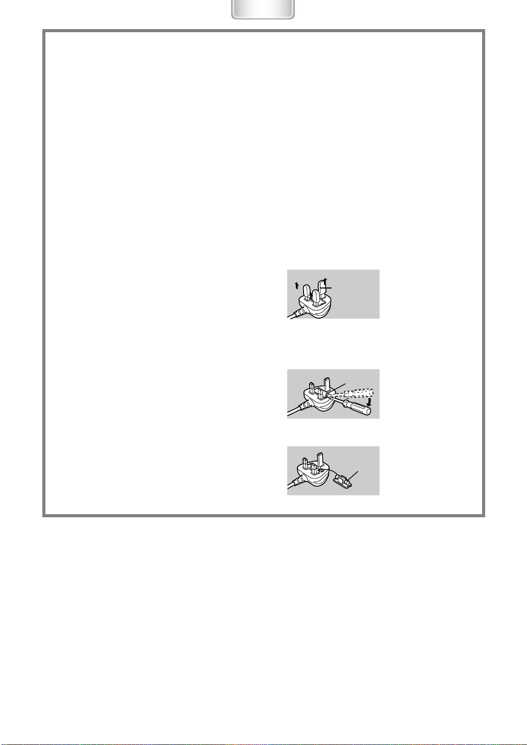
ªBefore Use
Remove the Connector Cover as follows.
Connector
Cover
ªHow to replace the Fuse
1) Remove the Fuse Cover with a screwdriver.
Fuse
Cover
2) Replace the fuse and attach the Fuse Cover.
Fuse
3333

Important Information
The Preheat function works so that high picture quality is
keeped when the surrounding temperature is low.
Therefore, even if pressing [PRINT] button, the operation
may stop for a while. (Printing starts within about 1 minute
automatically.)
If the temperature of the main unit become higher when
performing multiple copy, printing pauses automatically to
lower the temperature and the printing time becomes
longer. However, this is not a malfunction.
≥In the case of printing with using a personal computer,
the message of [Please wait until the temperature of
printer decreases.] is displayed on the monitor of a
personal computer.
≥In the case of printing with using a memory card, the
message of [Please wait until the temperature
decreases.] is displayed on the monitor of a TV.
When using the Photo Printer with PC Card (Especially,
Hard Disk Type Card), be careful because the
temperature of the surface on the Card may rise.
Before opening the CD-ROM package, please read the
following.
End User License Agreement
You (“Licensee”) are granted a license for the Software
defined in this End User Soft Agreement (“Agreement”) on
condition that you agree to the terms and conditions of
this Agreement. If Licensee does not agree to the terms
and conditions of this Agreement, promptly return the
Software to Matsushita Electric Industrial Co., Ltd.
(“Matsushita”), its distributors or dealers from which you
made the purchase.
Article 5 Reverse Engineering, Decompiling or
Disassembly
Licensee may not reverse engineer, decompile, or
disassemble the Software, except to the extent either of
them is permitted under law or regulation of the country
where Licensee resides. Matsushita, or its distributors will
not be responsible for any defects in the Software or
damage to Licensee caused by Licensee’s reverse
engineering, decompiling, or disassembly of the Software.
Article 6 Indemnification
The Software is provided “AS-IS” without warranty of any
kind, either expressed or implied, including, but not limited
to, warranties of non-infringement, merchantability and/or
fitness for a particular purpose. Further, Matsushita does
not warrant that the operation of the Software will be
uninterrupted or error free. Matsushita or any of its
distributors will not be liable for any damage suffered by
Licensee arising from or in connection with Licensee’s
use of the Software.
Article 7 Export Control
Licensee agrees not to export or re-export to any country
the Software in any form without the appropriate export
licenses under regulations of the country where Licensee
resides, if necessary.
Article 8 Termination of License
The right granted to Licensee hereunder will be
automatically terminated if Licensee contravenes of any
of the terms and conditions of this Agreement. In the
event, Licensee must destroy the Software and related
documentation together with all the copies thereof at
Licensee’s own expense.
Article 1 License
Licensee is granted the right to use the software,
including the information recorded or described on the
CD-ROM, instruction manuals, and any other media
provided to Licensee (collectively “Software”), but all
applicable rights to patents, copyrights, trademarks and
trade secrets in the Software are not transferred to
Licensee.
Article 2 Use by a Third Party
Licensee may not use, copy, modify, transfer or allow any
third party, whether free of charge or not, to use, copy or
modify the Software, except as expressly provided for in
this Agreement.
Article 3 Restrictions on Copying the Software
Licensee may make a single copy of the Software in
whole or a part solely for back-up purpose.
Article 4 Computer
Licensee may use the Software only on one computer,
and may not use it on more than one computer.
4444
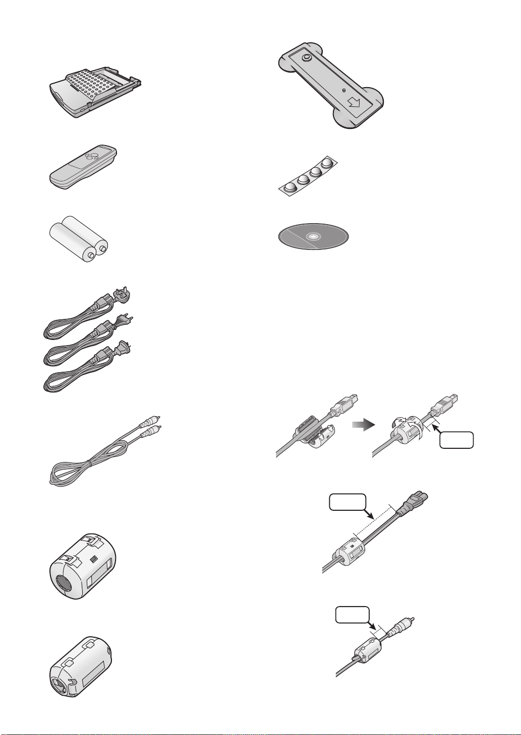
Supplied Accessories
Paper Cassette (VXA7522)
Remote Controller (N2QADB000006)
Stand for Vertical Layout (VYQ2551)
Feet for Horizontal Layout (VKA0376)
AA Size Batteries (x2)
AC Mains Lead
1
2
3
Video Cable (K1EA02BA0001)
SV-AP10B
K2CT3DA00003)
(
1
SV-AP10E/EN
(
K2CQ2DA00002)
2
SV-AP10EN
K2CJ2DA00002)
(
3
CD-ROM (VFF0171)
Important Information
(Including optional USB Connection Cable)
In order to prevent electromagnetic interference, install
the Clamp Filter (supplied) on the Cable as shown in the
figure.
≥After passing the Cable through the Clamp Filter and
looping it around once, close the Clamp Filter until it
clicks into place.
≥When you attach the Clamp Filter be sure to attach in
the side connected to the main unit.
USB Connection Cable (Not supplied)
1 cm
AC Mains Lead (Supplied)
Clamp Filter (x2) (Large Size)(for AC Mains Lead and
optional USB Connection Cable)
(J0KG00000053)
Clamp Filter (x1) (Small Size)(for Video Cable)
(J0KG00000036)
15 cm
Video Cable (Supplied)
1 cm
5555
For United Kingdom and Republic of Ireland
www.panasonic.co.uk
≥Order accessory and consumable items for your product with ease and confidence by telephoning our Customer Care
Centre Mon-Friday 9:00am-5:30pm. (Excluding public holidays.)
≥Or go on line through our Internet Accessory ordering application.
≥Most major credit and debit cards accepted.
≥All enquiries transactions and distribution facilities are provided directly by Panasonic UK Ltd.
≥It couldn’t be simpler!
Customer Care Centre
For UK customers: 08705 357357
For Republic of Ireland customers: 01 289 8333
Technical Support
For UK customers: 0870 1 505610
This Technical Support Hot Line number is for Panasonic PC software related products only.
For Republic of Ireland, please use the Customer Care Centre number listed above for all enquiries.
For all other product related enquiries, please use the Customer Care Centre numbers listed above.
(For UK Customers Only)
6666

Contents
Information for Your Safety ................................. 2
Caution for AC mains lead ..................................3
Important Information ..........................................4
End User License Agreement .............................4
Supplied Accessories.......................................... 5
Settings
Settings..............................................................31
Setting the Layout..............................................32
Setting the Owner ID .........................................32
Preparation
Controls and Components...................................8
Inserting Remote Control Batteries ...................10
Using the Remote Controller.............................10
Installation and Connections .............................11
Inserting a Card.................................................12
Inserting Paper..................................................12
Inserting the Ink Cassette..................................13
MENU Interface.................................................13
MENU Controls .................................................14
On Screen Display ............................................14
Basic Functions
Try Print.............................................................15
Switching the Pictures between
the Album Display and the Index Display.......... 17
To Enlarge/Reduce/Rotate/Move the Picture.... 17
Printing Batches/Indexing..................................18
Using Date Search When Printing.....................18
Printing With a DPOF Card ...............................19
Copying/Erasing Images from a Card ..............20
Recording Titles onto Cards..............................21
Erasing Titles From Cards.................................21
Viewing Slide Shows.........................................22
Connecting and Operating with a
personal computer
Operating environment......................................33
Installing the Printer Driver ................................34
Uninstalling the Printer Driver ............................41
Printing from PC ................................................42
Caution for Use..................................................45
Others
After Use............................................................46
Precautions........................................................46
Q&A ...................................................................49
Before Requesting Service................................50
Error Messages .................................................52
Error Messages for Printer Driver......................53
Specifications.....................................................54
Multiple Functions
Printing Multiple Screen Shots of
the Same Picture (MULTI FRAME MODE) .......23
Returning a Multiple Screen
to a Single Screen.............................................23
Printing Multiple Screen Shots of
Different Pictures...............................................24
Creating a Personalized Picture Calendar ........26
Inserting Wallpaper and Printing .......................27
Title Functions
Inserting Illustrations and Printing .....................28
Switching Displays
(Indicate/Don’t indicate/Clear) ...........................28
Inserting Characters and Printing......................29
Print in Sepia Tone............................................30
7777
Preparation
SET
Í
DISPLAY/
CANCEL
ERROR
PRINT
MENU
7 8
13
1
2
3
4
5
6
Preparation
Controls and Components
Power Lamp [Í]
1
When you turn the power on, the Power lamp
turns green. When you turn the power off, the
Power lamp turns red, and all images in the
Photo Printer’s memory are deleted.
Power Button [Í]
2
Press to turn Photo Printer on/off.
PRINT Button
3
Press this button to print images.
MENU Button
4
Use this button to display the menu screen.
2134 Buttons/SET Button
5
2134 Buttons:
Use these buttons to select menu choices and
card images.
SET Button:
Use this button to enter various selections.
DISPLAY/CANCEL Button
6
DISPLAY Button:
Changes the picture display on a card among a
Single Screen Display, an Index Display and an
Album Display.
CANCEL Button:
Use to cancel printing and other such
processes.
Use to exit MENU.
Remote Control Receiver
7
Receives the signal from the remote controller.
Do not obstruct the remote control receiver to
be emitted.
Error Lamp
8
Flashes when the error has occurred.
14
15 16
EJECT
ACCESS
9
10
11
PC CARD
SD MEMORY CARD
12
Card Access Lamp
9
Light while the Photo Printer is making an
access to the Card.
PC Card Eject Button
10
SD Memory Card/MultiMediaCard Insert
11
Location
PC Card Insert Location
12
Paper Cassette Insert Location
13
Stand for Vertical Layout
14
Use the stand for vertical layout.
Ink Cassette Eject Lever
15
Ink Cassette Insert Location
16
Power Socket
17
Connects the AC Mains Lead (supplied).
Paper Removal Port
18
Cord Stopper
19
Fixes the AC Mains Lead.
USB Socket
20
Connects the USB Connection Cable (not
supplied) to the USB Socket for PC.
VIDEO OUT Socket
21
Connect the Video Cable (supplied) to Video
Input Socket of TV.
20
21
VIDEO
OUT
17
18
19
8888
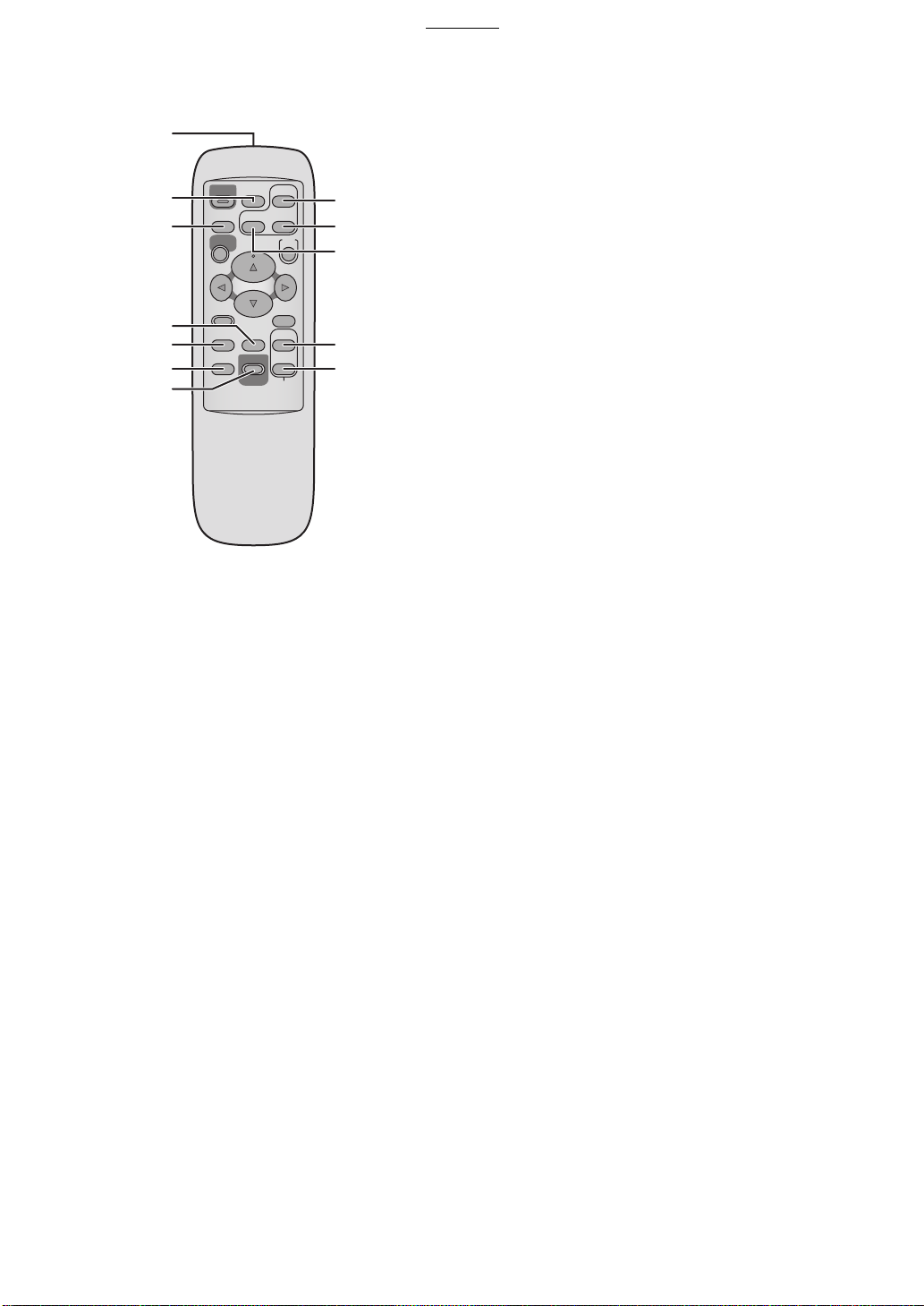
Controls and Components (Cont.)
ªRemote Controller
1
2
3
Í
CARD SELECT
PRINT
ALBUM
ROTATE
ZOOM IN
ZOOM OUT
SET
8
9
10
DISPLAY/
DATE
DPOF/ALL
PRINT
CANCEL
COPY
SELECT
MULTI
11
12
MENU
4
5
6
TITLE
NUMBER
7
Preparation
11
12
MULTI (COPY) Button
Press this button to select numbers of multiple
screen shots of the same picture.
MULTI (SELECT) Button
Press this button to select numbers of multiple
screen shots of the different picture.
The buttons below have the same functions as
ones of the Photo Printer. (The same number
as the main unit is used.)
2 Power Button [Í], 3 PRINT Button, 4 MENU
Button, 5 2134 Buttons, 5 SET Button, and
6 DISPLAY/CANCEL Button
1
Remote Control Transmitter
ALBUM Button
2
Press this button to change the screen between
the Album Display and Index Display.
CARD SELECT Button
3
Press this button to change the input between
SD Memory Card or MultiMediaCard and PC
Card.
DATE Button
4
Press this button to add the date when the
picture was taken in the lower right corner.
TITLE Button
5
Press this button to display the menu screen of
[FUNCTION].
NUMBER Button
6
Press this button to select the copies of print.
PRINT (DPOF)/PRINT (ALL) Button
7
PRINT (DPOF) Button:
Press this button to print the pictures DPOF was
set.
PRINT (ALL) Button:
Prints all pictures when there are no pictures
DPOF was set in the Card.
ZOOM IN Button
8
Press this button to enlarge the picture and
characters.
ZOOM OUT Button
9
Press this button to reduce the picture and
characters.
ROTATE Button
10
Press this button to rotate the picture and
characters.
9999
Preparation
A
A
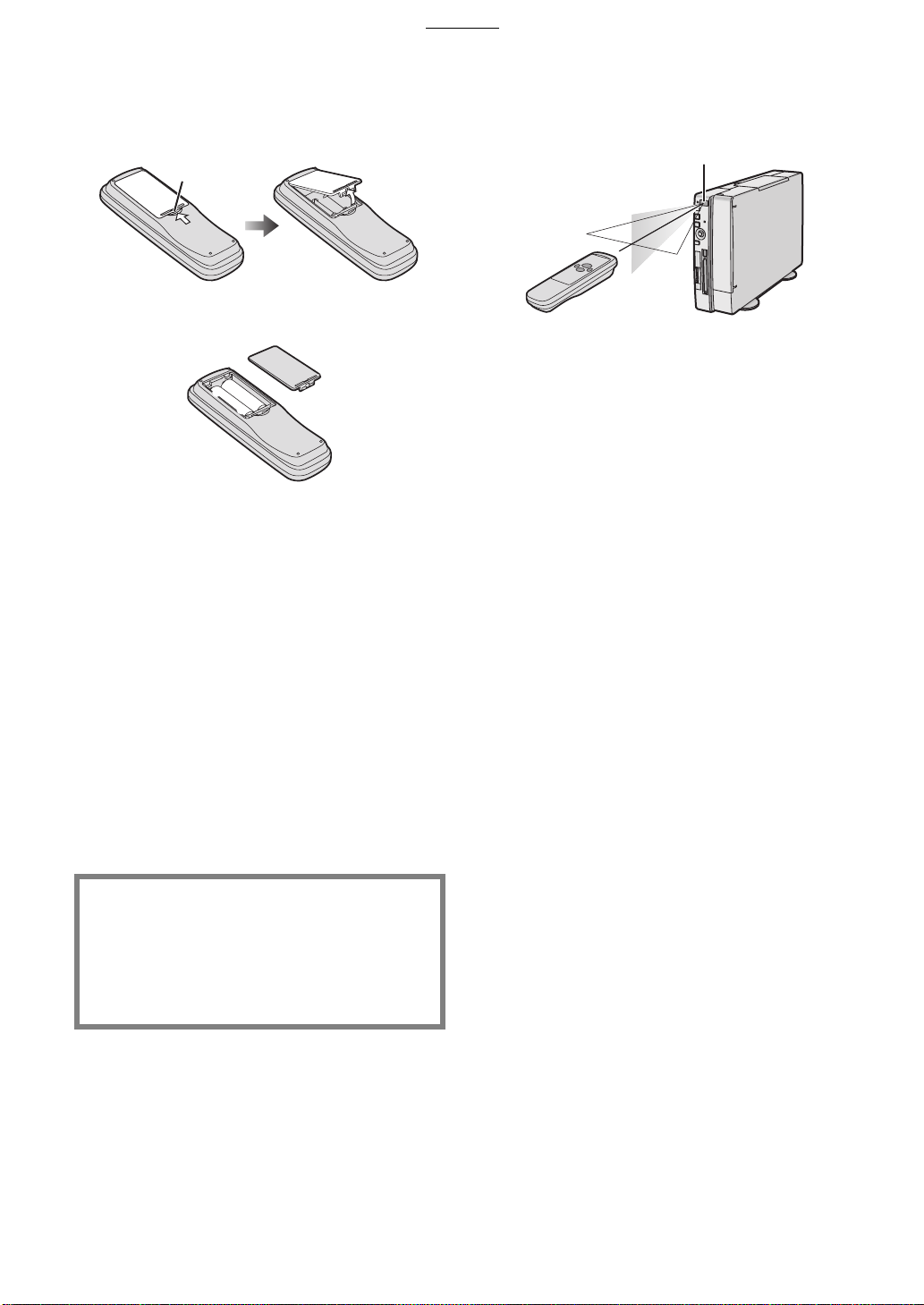
Inserting Remote Control Batteries
While pressing the indentation A in the
1
direction indicated by the arrow, lift the
cover up.
Insert the batteries (supplied) with the
2
polarity (
Cover is returned.
3
Precautions for Battery Replacement
The service life of the batteries is approximately 1 year.
However, it varies considerably depending on the
frequency of use.
≥When they are exhausted, replace them with two AA,
UM3, or R6 size batteries.
≥When the batteries are exhausted, remove them
immediately and dispose of them correctly.
≥Make sure that the batteries are inserted with the
polarity (
≥Do not mix old battery with new battery.
≥Do not mix different battery types, i.e. Alkaline and
Manganese.
≥Do not use rechargeable (Ni-Cd) batteries.
≥Do not heat or short-circuit the batteries.
≥When you do not use the remote control for a long time,
take out the batteries and store them in a cool, dry
place.
and -) correctly aligned.
+
+
-
-
+
and -) correctly aligned.
+
Using the Remote Controller
Direct the remote controller to the remote
1
control receiver
≥Distance from the Photo Printer: Within approximately
7m
≥Angle: Within approximately 40 degrees in the vertical
directions and 60 degrees in the horizontal directions
from the central axis
≥Do not lay the obstruction between the Photo Printer
and remote controller.
≥Do not expose the direct sunlight or strong light on the
remote control receiver.
≥When attaching the paper cassette, you cannot use the
remote controller from the right angle or lower right
angle.
≥The receiver range reverses between the Vertical and
Horizontal layout.
and press a button.
A
CAUTION
Danger of explosion if battery is incorrectly
replaced.
Replace only with the same or equivalent type
recommended by the manufacturer.
Dispose of used batteries according to the
manufacturer’s instructions.
10
10
1010
Preparation
Installation
Vertical Layout
Horizontal Layout
Connections
TV
Installation and Connections
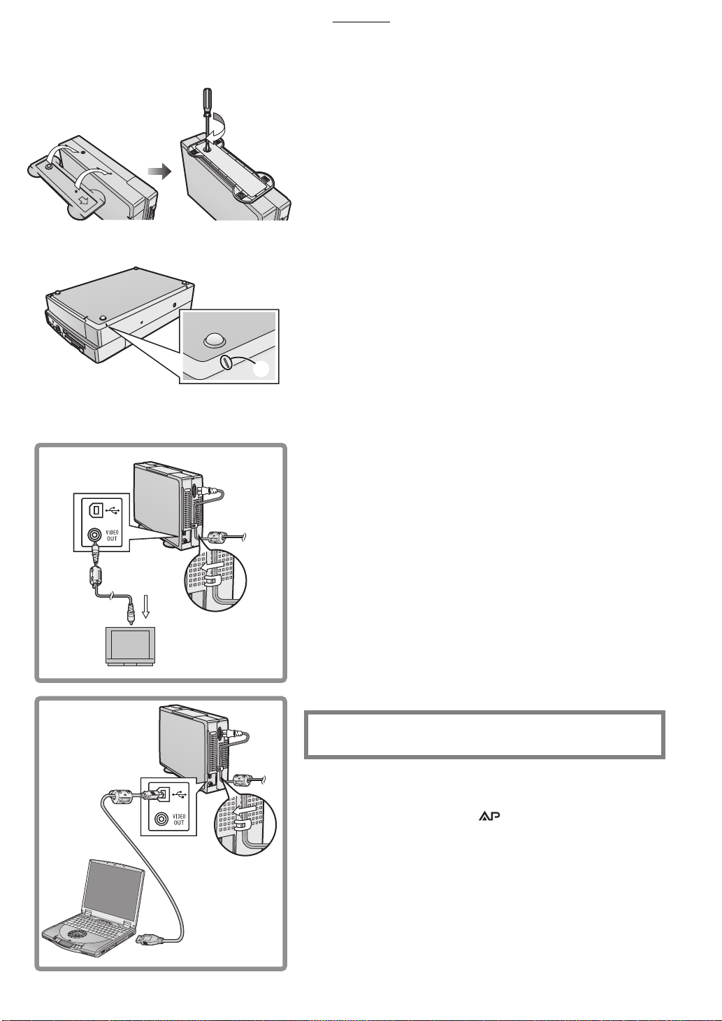
ª Installation
Be sure to install the stand when selecting the Vertical layout. And the
feet when selecting the Horizontal layout.
Installation for Vertical Layout
Install the stand to the hole like a illustration.
1
Tighten the screw and fix the main unit and the stand.
2
Installation for Horizontal Layout
Attach the feet for Horizontal Layout to the four corners
1
of the side which does not have a vent of the main unit.
(Attach them to the position of the mark A.)
ª Precautions During Setup
As this printer gets hot during use, operate it in a well ventilated area.
Place printer at least 10 cm away from any walls to the left, right, above
or rear of printer. Do not place any objects on top of printer.
≥When detaching the feet, coating may be peeled off. Do not detach
them after attaching them.
A
1
≥Select [Vertical] or [Horizontal] under [Layout] after installation and
connections. (Initial setting: [Vertical])
≥If you do not select the [Layout] menu, the direction of operation of the
Cursor buttons is different when using with the Horizontal layout.
ª Connections
For Connection to TV
Connect the AC Mains Lead (supplied) to the main unit
1
and Household Mains Socket with the cord hooked to
the cord stopper.
Connect the Video cable (supplied) to [VIDEO OUT]
2
Socket on main unit and the Video Input Socket on TV.
≥After connections, turn on the Photo Printer and TV, and switch the
input to the video input.
PC
For Connection to PC
Connect the AC Mains Lead (supplied) to the main unit
2
1
and Household Mains Socket with the cord hooked to
the cord stopper.
Connect the USB Connection Cable (not supplied) to the
2
USB Socket on main unit and the USB Socket on PC.
≥General USB A-B Cable can be used.
≥After connections, see page 33.
THE SOCKET OUTLET SHALL BE INSTALLED NEAR THE
EQUIPMENT AND SHALL BE EASILY ACCESSIBLE
.
1
ª Paper That Can Be Used For Printing
The Photo Printer can use the following types of paper. Use Ink
Cassette/Paper Sets that bear the mark. (Print Sets that bear the
µ mark, the ∂ mark, or no mark at all cannot be used.)
≥9 x 12 cm printing paper* *with borders: The Ink Cassette/Paper Set
2
VW-APA50E is required.
≥16 Pre-Cut Adhesive paper (overcoat type): The Ink Cassette/Paper
Set VW-APASD16E is required.
≥10 x 15 cm printing paper* (overcoat type) *without borders: The Ink
Cassette/Paper Set VW-APKC36E is required.
≥Use the Ink Cassette with the paper provided in the same box.
11
11
1111
2
1
1
Preparation
Inserting a Card
ª When using an SD Memory Card or a
MultiMediaCard
1
Insert the card all the way into the slot.
≥The Card Access Lamp lights.
[Removing the Card]
Push the card.
1111
Remove the card.
2222
ª When Using a PC Card
1
Insert CF Card all the way into 1 (PC Card Adaptor/
Product Sold Separately).
2
Insert 1 into the Photo Printer.
[When Removing the Card Adaptor]
Press 2.
1111
Remove 1.
2222
≥Never take the card out or turn off the power while the card is being
accessed. This could damage the format of the card and make it
unusable.
≥Insert/remove cards only when the power is off.
≥Card images are formatted as JPEG baselines (JFIF, EXIF, DCF
[Design rule for Camera File system], CIFF, SISRIF) TIFF (Baseline
TIFF Rev.6.0RGB Full Colour Images compatible). (Some types
cannot be fully used)
≥Do not insert/remove only the card with the card adaptor inserted.
5
3
2
6
7
4
Inserting Paper
1
Open the lid of the paper cassette (included) 1, spread
out
, and stand up (or push down) 3.
2
≥When using 9 x 12 cm printing paper or 16 Pre-Cut Adhesive
printing paper, spread
≥When using 10 x 15 cm printing paper, spread
.
3
Face the white (print) side of the paper up, and insert
2
under
While opening the paper cassette door 6 and pushing
3
the Photo Printer with your hand, insert the paper
cassette all the way into
≥Insert up to 25 sheets of 9 x 12 cm printing paper, or up to 36 sheets of
the other types of paper.
≥Do not pull out the paper cassette during printing.
≥Pull out the paper cassette and close the paper cassette door after
use.
≥Do not fold, bend, or turn paper upside down when inserting into
printer.
≥If you do not insert the paper cassette all the way, when pressing the
[PRINT] button, the error message of [There is no paper cassette] is
displayed.
is the perforation line).
4 (5
, and stand up 3.
2
.
7
, and push down
2
12
12
1212
Preparation
1
2
3
2
1
A
2
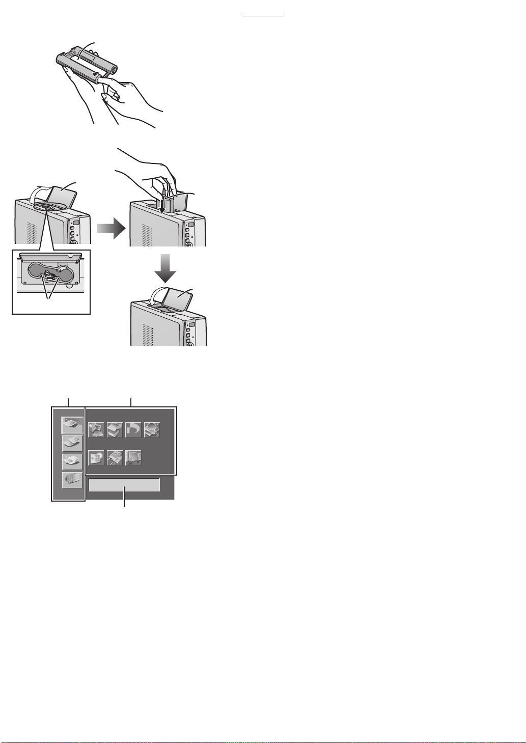
Inserting the Ink Cassette
Use your finger to push in the hole with the arrow, and
1
turn it in the direction of the arrow. Tighten any slack in
1
(Ink Film).
≥The Ink Cassette is included in the Ink Cassette/Paper Set
(optional).
Open 2 (Ink Cassette Compartment Door), place the
2
side that contains
insert the Ink Film all the way into the Ink Cassette, and
2
close
≥Do not touch the Ink Film in the Ink Cassette, and do not pull it out of
the cassette.
≥Close the Ink Cassette Compartment Door.
≥Do not peel off the label on the Ink Cassette.
≥When all of the Ink film in an Ink Cassette has been used up, replace
the Ink Cassette with a new one. Used Ink Cassettes cannot be
reused.
.
3
(small hole in Ink Cassette A) up,
12
BASIC
FUNCTION
A
EFFECT
OPTION
Input
Batch
DPOF
DPOF
SlideCardAlbum
Search
3
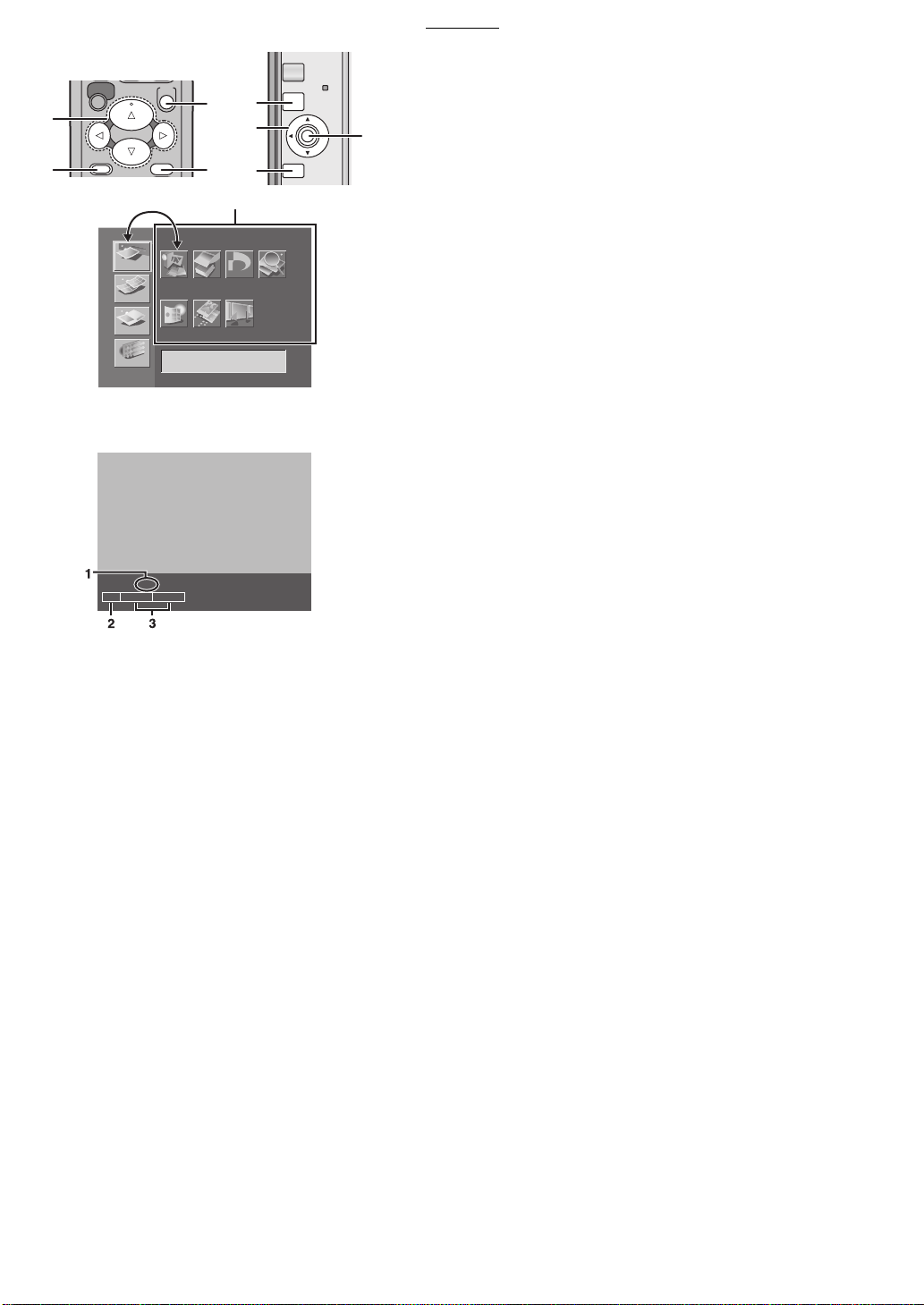
MENU Interface
MENU Categories
1
≥The Photo Printer is divided into 4 major categories.
MENU Contents
2
≥Select the specific MENU you desire here.
Description/Control Display
3
≥The presently selected MENU’s description as well as control
confirmation messages are displayed in this area.
13
13
1313
Preparation
B
A
PRINT
MENU
Standard x1
DATE
BASIC
FUNCTION
A
EFFECT
OPTION
SD/MMC
SET
DISPLAY/
CANCEL
Input
PC CARD
Batch
C
D
A
B
D
32
DPOF
DPOF
SlideCardAlbum
SET: Zoom set up
Search
PRINT
MENU
1/39
SET
DISPLAY/
CANCEL
ERROR
MENU Controls
Use the MENU Mode as follows.
1:Press
C
2:Use the 21 Buttons
to display the MENU screen.
A
to switch between MENU categories and
B
MENU contents.
to move within the MENU Contents. To
C
B
.
3:Use the 2134 Buttons
enter your selection, press
4:Press
5:Press
to enter your selection.
C
to exit the MENU.
D
On Screen Display
The screen display disappears a few seconds later, it appears again
when pressing the 34 Buttons.
Number display
1
Date display
2
Input display
3
14
14
1414
Basic Functions
CARD SELECT
PRINT
MENU
ZOOM OUT
ROTATE
SET
DISPLAY/
CANCEL
Basic Functions
B
D
1
2
4
BASIC
FUNCTION
EFFECT
OPTION
Layout
SFTWT SM
13
20
27
14
21
28
A
15
22
29
A
C
7
7
5
5
3
3
Number Date
Layout
365421
16
25
23
30 31
D
C
2
Owner ID
Vertical
Horizontal
121110987
1926172418
PRINT
MENU
ERROR
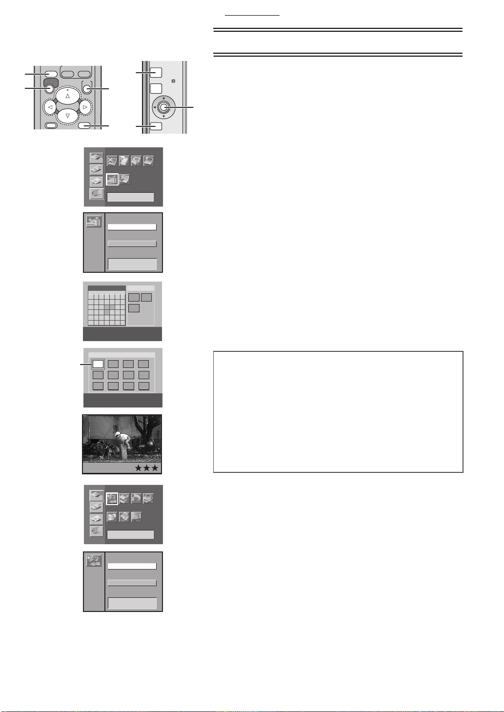
Try Print
≥The explanations below are made for the Vertical layout and the Album
SET
DISPLAY/
CANCEL
Display setting.
A
ª Printing Images From a Card
≥Make sure that paper, the Paper Cassette and the Ink Cassette are all
inserted.
≥Insert a card into the Photo Printer.
≥Turn on the power.
Picture
Tri m
Select [Layout] under [OPTION] on the MENU screen,
1
and press
Select [Vertical] or [Horizontal], and press A.
2
Press B (CARD SELECT Button).
3
Using the 21 Buttons, select 1 the date you wish.
4
(SET Button).
A
Selected date: Yellow
Date with the picture: Light Blue
Using C (DISPLAY Button), change to the Index Display
5
and using the 2134 Buttons, align
(blue frame)
1
over the image you wish to print.
≥You can enlarge, reduce and rotate the picture here. (P17)
Pressing
6
Press
7
≥Printing begins.
≥The “j” symbols all change to “¡” symbols. Once they disappear,
printing is complete.
changes to a Single Screen Display.
C
(PRINT Button).
D
5
6
1
2
1
FUNCTION
EFFECT
OPTION
Input
BASIC
To Operate with the Button of the main unit
Select [Layout] under [OPTION] on the MENU screen,
1111
and press
Select [Vertical] or [Horizontal], and press A.
2222
Select [Input] under [BASIC] on the MENU screen,
3333
and press
Using the 34 Buttons, select [SD/MMC] or [PC card],
4444
and press
≥Go to the Step 5 on the operations with the remote controller after
the operations above.
≥Some image on the display may be unsteady depending on the card
DPOF
Input
Batch
DPOF
Search
A
SlideCardAlbum
SD/MMC
PC card
being used. If “The picture is unreadable.” or “The card can’t be used.”
error message appears, or if “x” symbol appears even though the
image is stored, turn off the power, remove the card and re-insert it.
≥A white border may appear around the card’s image, but this will not
affect the printed image.
≥Do not pull out the papers when they are moving during printing. Do
not remove the paper cassette or the Ink Cassette.
≥Do not put 11 or more printing papers on the receiving position the
causing the paper jam.
≥It may take some time until the picture is displayed depending on the
card.
≥The picture on the TV screen may flicker depending on the card.
However it does not affect on the printing image.
≥When saving the picture file on PC, the save date is displayed.
≥It may take rather time to print two or more sheets or print in the low or
high temperature.
(SET Button).
A
(SET Button).
A
(SET Button).
A
15
15
1515

COPY
SELECT
DATE
NUMBER
PRINT
MENU
TITLE
DPOF/ALL
SET
DISPLAY/
CANCEL
C
B
Basic Functions
ª Forwarding/Backwarding the Screen
When 13 or more images are recorded on a card, aligning 1 (blue
frame) on the places indicated in the diagram to the left and pressing the
button will forward/backward the screen.
1234
5678
9101112
1234
5678
9101112
1
1
A
ª Reprinting the Image
Press A to make the Index Display appear after printing is complete
and the Album Display appears and then press the PRINT Button
B
after selecting the picture in the blue frame.
≥If installing a different Ink Cassette before reprinting when using a
card, re-select the image.
13
ª Printing Multiple Copies of a Single Image
1
Press C (NUMBER Button) when the picture is
displayed.
≥The number of prints increases each when pressing
≥The Photo Printer can continuously print up to 10 copies of the same
image.
13
14
16
15
17
18
20
19
22
21
24
23
≥The number of pages remaining to be printed (including the currently
printing page) appears in the lower left corner of the screen.
C
.
To Operate with the Button of the main unit
See page 31.
ª Paper Jams
≥A “Paper jam has occurred. Remove paper and press [PRINT].” error
or the right
1
1 or 2
.
1
message appears. Remove paper out of the left side
, and remove the Ink Cassette. Make sure no more paper is
side
2
stuck inside, then re-install the Ink Cassette. Press the Print button.
The error message will disappear and printing will continue.
≥If you have trouble removing the paper, turn the power off, and then
back on again. Proceed to remove the paper from either
≥If the paper stops moving during print even though no error messages
appear, do not remove the paper. Wait for printing to resume
automatically.
2
16
16
1616
Basic Functions
CARD SELECT
PRINT
ZOOM IN
Í
ALBUM
ZOOM OUT
ROTATE
SET
CARD SELECT
PRINT
MENU
ZOOM IN
Í
ALBUM
ZOOM OUT
ROTATE
SET
DISPLAY/
CANCEL
A
1
SFTWT SM
13
20
27
1
2
MENU
SET
DISPLAY/
CANCEL
365421
121110987
19261724182514
15
16
21
22
23
28
29
30 31
BASIC
FUNCTION
EFFECT
OPTION
Album
A
Input
DPOF
Batch
DPOF
SlideCardAlbum
Indicate
Don't indicate
Search
Display and the Index Display
You can make the pictures on each recorded date appear using the
A
Album Display.
Press A (ALBUM Button) when the pictures are
1
displayed.
≥The pictures can be also switched between the Album Display and
the Index Display each when pressing
To Operate with the Button of the main unit
Select [Album] under [BASIC] on the MENU screen,
1111
and press
Using the 34 Buttons, select [Indicate] or [Don’t
2222
indicate], and press
≥When saving the picture file on PC, the save date is displayed.
.
A
.
A
A
.
Switching the Pictures between the Album
C
1
2
3
To Enlarge/Reduce/Rotate/Move the Picture
≥Select the INPUT method.
≥Make the picture appear in the Single Screen Display.
A
Press A (ZOOM IN Button) to enlarge the picture.
1
≥The picture can be enlarged until 3 times.
Press B (ZOOM OUT Button) to reduce the picture.
2
A
B
D
B
PRINT
MENU
SET
DISPLAY/
CANCEL
ERROR
≥The picture can be reduced until 1/2 times.
Press C (ROTATE Button) to rotate the picture.
3
≥The picture can be rotated by 90 degrees clockwisely whenever
the button is pressed.
Using the 2134 Buttons, move the picture after
4
enlarging/reducing/rotating or pressing
D
.
To Operate with the Button of the main unit
Press A.
1111
Using the 2134 Buttons, move the picture.
2222
Press B.
3333
Using the 21 Buttons, rotate the picture and Using
4444
the 34 Buttons, enlarge or reduce the picture.
≥Pressing B returns to Step 2.
≥Make the picture appear in the Index Display and then make the same
picture appear again with the [DISPLAY] button.
≥When the picture is enlarged, the picture quality may be inferior.
≥You cannot enlarge, reduce, rotate or move the picture when setting to
the multi select display or the calendar display.
17
17
1717

Basic Functions
PRINT
MENU
SET
DISPLAY/
CANCEL
PRINT
MENU
SET
DISPLAY/
CANCEL
1
2
4
6
BASIC
FUNCTION
EFFECT
OPTION
Batch
A
B
A
B
DPOF
Input
Batch
DPOF
SlideCardAlbum
2
All pictures
Selected pictures
Selected date
All index
Selected index
Selected date index
Clear selected mark
PRINT
MENU
Search
SET
DISPLAY/
CANCEL
ERROR
1
3
5
7
Printing Batches/Indexing
Multiple pictures can be automatically printed from a card.
Furthermore, 25 frames of images on a card can be indexed and printed.
A
≥Select the INPUT method.
≥If you select all pictures, begin from Step 2.
1
Select the pictures, and mark them with A (¥).
2
Select [Batch] under [BASIC] on the MENU screen, and
press
Select a MENU you wish to use, and press
Print a batch of all pictures.
1
Print a batch of selected pictures.
2
Print a batch of selected pictures with the Album function.
3
Index all pictures.
4
Index selected pictures.
5
Print a batch of Index selected pictures with the Album function.
6
Clear a batch of selected pictures.
7
≥Press
≥You can print a batch of pictures when also pressing [PRINT (DPOF/
ALL)] Buttons. (When you insert DPOF cards, only the pictures that
DPOF setting were made are printed.)
≥Pictures will be printed in the order selected.
≥When using [Selected pictures],(
is complete. When using [Selected index], marks will not disappear
after printing.
≥All pictures stored to memory will be lost if the power is turned off.
≥If [With date] is selected under [Date], the date will appear on all
indexed pictures. However, dates cannot be verified on the TV Screen.
A
to cancel.
B
.
.
A
¥) mark will disappear when printing
B A
1
2
BASIC
Input
FUNCTION
A
EFFECT
OPTION
21
Search
3
Batch
Year
Month
Date
Year
Month
Date
B
DPOF
DPOF
SlideCardAlbum
:
October
:
:
:
October
:
:
2002
2002
PRINT
MENU
ERROR
Using Date Search When Printing
Dates are recorded for pictures that were recorded on cards with Digital
Movie Cameras or Digital Cameras. Using this information, pictures
Search
SET
DISPLAY/
CANCEL
taken on the designated date(s) can be printed.
A
≥Select the INPUT method.
1
Select [Search] under [BASIC] on the MENU screen, and
press
2
Enter the period you wish to search (Begin Search Date/
A
.
End Search Date), and press
A
.
21 Buttons: Change the Date
43 Buttons: Move the Cursor
≥Years can be entered from 1980 to 2040.
3
1
30
Confirm the pictures you found (¥) in the lower right
corner, and press
≥A batch of the searched pictures is printed.
≥If no images could be found within the designated search period, a “A
picture wasn’t found.” message will appear.
≥To print all images that were found as a batch, return to the MENU
screen and select [Selected pictures], under [Batch] in [BASIC].
≥The selected pictures can also be viewed as a Slide Show.
≥When searching the date on the Album Display, the screen switches to
the Index Display.
≥When saving the picture file on PC, the save date is displayed.
B
.
18
18
1818

Basic Functions
COPY
SELECT
MULTI
DATE
NUMBER
TITLE
PRINT
DPOF/ALL
A
1
2
BASIC
FUNCTION
EFFECT
OPTION
DPOF
DPOF
PRINT
MENU
ERROR
Printing With a DPOF Card
When a DPOF card that contains pictures and print counts set with a
Digital Video Camera or a Digital Camera is inserted, printing can be
A
SET
DISPLAY/
CANCEL
automatically be performed.
≥Insert a DPOF card.
≥Select the INPUT method.
1
Press A (DPOF Button) when the pictures are
displayed.
DPOF
Input
Batch
DPOF
Search
A
SlideCardAlbum
Start printing
Return
≥Printing begins.
DPOF stands for Digital Print Order Format. Using a Digital Video
Camera or a Digital Camera, this adds printing information to stored
pictures on cards so they can be applied to DPOF systems.
≥When you insert the cards DPOF setting is not made, all the pictures
are printed by pressing [PRINT (DPOF/ALL)] Button.
≥The Photo Printer cannot configure DPOF.
≥Confirm settings on the equipment on which the settings were made.
≥Setting the print count in [Number] under [OPTION] will have no effect.
Only the DPOF configured print count will be printed.
≥If 100 or more copies are set to be printed on the DPOF settings, only
99 will be printed.
≥If you do not use the DPOF-configuring device to set the date on cards,
they cannot be entered even when printing a batch of pictures.
To Operate with the Button of the main unit
Select [DPOF] under [BASIC] on the MENU screen,
1111
and press
Using the 34 Buttons, select [Start printing] or
2222
[Return], and press
.
A
.
A
19
19
1919

Basic Functions
PRINT
MENU
SET
DISPLAY/
CANCEL
1
2
3
4
A
B
BASIC
FUNCTION
EFFECT
OPTION
Card
Card
MENU
Copying/Erasing Images from a Card
Images can be mutually copied to or erased from SD Memory/
B
SET
DISPLAY/
CANCEL
A
MultiMediaCards and PC Cards.
≥Unlock the card when inserting the SD Memory Card.
≥Insert the card to both insert locations when copying the picture.
≥Select the card that contains the images you wish to copy or
DPOF
Input
Batch
DPOF
Search
A
SlideCardAlbum
Picture
Title
erase in the INPUT method.
1
Select [Card] under the [BASIC] on the MENU screen,
and press
2
Select [Picture], and press A.
3
Select either [Copy] or [Delete], and press A.
A
.
≥Select the date, and press A.
4
Select an image, press A, confirm the screen, and press
again.
A
≥Press B to cancel.
≥Images will be permanently deleted.
≥Multiple copies of images cannot be selected at one time.
Copy
Delete
≥You cannot copy or erase the picture and title simultaneously.
≥Do not pull out during copying or erasing.
≥You cannot copy or erase the locked picture. Unlock the picture on the
equipment which locked it.
≥You cannot copy the picture to the card there is no space left.
20
20
2020

Basic Functions
PRINT
MENU
SET
DISPLAY/
CANCEL
1
1
2
33
1
2
FUNCTION
EFFECT
OPTION
Card
Card
A
B
BASIC
A
B
DPOF
Input
Batch
DPOF
SlideCardAlbum
Picture
Title
Record to SD / MMC
Record to PC card
Delete
MENU
Search
SET
DISPLAY/
CANCEL
Recording Titles onto Cards
The Photo Printer can create titles through its Title Functions
(Illustrations/Characters). Created titles can then be recorded onto
A
cards.
≥Unlock the card when inserting the SD Memory Card.
≥Display the created title.
1
Select [Card] under [BASIC] on the MENU screen, and
press
2
Select [Title], and press A.
3
Select [Record to SD/MMC] or [Record to PC card], and
press
4
Enter the creation date, and press A.
A
A
.
.
21 Buttons: Change the Numbers
43 Buttons: Move Cursor
5
Confirm the picture, and press A.
≥Press B to cancel before pressing A.
≥Do not pull out the card while recording titles onto card.
≥Titles recorded to cards can be used in this unit.
≥Only titles can be recorded to cards. Pictures containing both titles and
images cannot be recorded.
Erasing Titles From Cards
Titles recorded on cards can be deleted.
4
5
3
4
21
21
Year 2002:
Year 2002:
Card
Card
Month October:
Month October:
Date : 10
Date : 10
Record to SD / MMC
Card
Record to PC card
Delete
≥Unlock the card when inserting the SD Memory Card.
Select [Card] under [BASIC] on the MENU screen, and
1111
press
Select [Title], and press A.
2222
Select [Delete], and press A.
3333
Select a picture, and press A.
4444
≥Press B to cancel before pressing A.
≥Titles are permanently deleted.
≥Titles on separately sold MultiMediaCards cannot be deleted.
≥Titles locked on Digital Video Camera cannot be erased.
A
.
21
21
2121

Basic Functions
PRINT
MENU
SET
DISPLAY/
CANCEL
1
2
3
BASIC
FUNCTION
EFFECT
OPTION
Slide
A
B
Input
A
B
DPOF
Batch
DPOF
SlideCardAlbum
All pictures
Selected pictures
Selected date
DPOF
MENU
Search
SET
DISPLAY/
CANCEL
Viewing Slide Shows
The Photo Printer can automatically display a continuous show of
selected pictures within a card.
A
≥To view DPOF configured pictures, insert a card with DPOF
settings.
≥Select the INPUT method.
≥To view all pictures or DPOF configured pictures within a card,
begin from Step 2.
1
Select the pictures, and mark them with A (¥).
≥To remove a picture, select the picture and press A. The ¥
symbol disappears.
2
Select [Slide] under [BASIC] on the MENU screen, and
press
3
Choose [All pictures], [Selected pictures], [Selected
date] or [DPOF], and press
≥Press
≥Pictures may take a few moments to load, depending on the picture
size.
≥Do not remove the card during a Slide Show.
≥When setting the Slide Show with the other equipment, the pictures set
with the other equipment has a more priority than DPOF configured
pictures. Cancel the setting with the other equipment.
≥When selecting [Selected date], all pictures with date selected on the
Album Display appears.
≥Slide Show is repeated when you do not press
≥The characters of [Slide show] are displayed in the lower right corner of
the screen during Slide Show.
A
B
.
to cancel.
A
.
.
B
22
22
2222

Multiple Functions
COPY
SELECT
MULTI
DATE
NUMBER
PRINT
MENU
TITLE
PRINT
DPOF/ALL
SET
DISPLAY/
CANCEL
COPY
SELECT
MULTI
DATE
NUMBER
TITLE
PRINT
DPOF/ALL
Multiple Functions
B
2
1
2
FUNCTION
EFFECT
OPTION
Copy
BASIC
A
Standard
Wallpaper
B
Copy
SelectACalendar
Picture 2x
Picture 4x
Picture 9x
Picture 16x
PRINT
MENU
SET
DISPLAY/
CANCEL
ERROR
Printing Multiple Screen Shots of the Same
Picture (MULTI FRAME MODE)
The Photo Printer can divide the screen into 2, 4, 9 or 16 sections, and
print multiple screen shots of the same picture.
A
≥Select the INPUT method.
≥Select the picture and make the Single Display appear.
1
Press A (MULTI (COPY) Button) when the pictures are
displayed.
≥[Copy16], [Copy9], [Copy4], [Copy2] or [Standard] is displayed in
the left lower corner of the screen each when pressing
2
Confirm the picture, and press B to print.
To Operate with the Button of the main unit
Select [Copy] under [FUNCTION] on the MENU
1111
screen, and press
Using the 34 Buttons, select [Picture 2 x], [Picture
2222
4 x], [Picture 9 x] or [Picture 16 x] and press
≥Go to the Step 2 on the operations with the remote controller after
the operations above.
≥You can also select multiple picture copies and print them as a batch.
≥If [With date] is selected under [Date], the date will appear on each
printed section of the picture. However, dates cannot be verified on the
TV Screen.
≥When an Ink Cassette for 16 Pre-Cut Adhesive paper is inserted, the
screen will automatically be divided into 16 sections. If the Ink Cassette
is removed, the screen will not automatically return to a single screen.
.
A
A
A
.
.
1
BASIC
FUNCTION
EFFECT
OPTION
A
B
Standard
Wallpaper
Copy
MENU
SelectACalendar
SET
DISPLAY/
CANCEL
A
Returning a Multiple Screen to a Single
Screen
Dividing on screens are performed in [FUNCTION] (Copy/Select/
Calendar/Wallpaper). To undo these functions.
1
Press A (MULTI (COPY) Button) or B (MULTI (SELECT)
Button) until [Standard] is displayed in the left lower
corner of the screen when the pictures are displayed.
≥A single screen can be returned in [Standard] under [FUNCTION]
on the MENU screen.
To Operate with the Button of the main unit
Select [Standard] under [FUNCTION] on the MENU
1111
screen, and press
23
23
2323
.
A

COPY
SELECT
MULTI
DATE
NUMBER
PRINT
MENU
TITLE
PRINT
DPOF/ALL
SET
DISPLAY/
CANCEL
D
E
1
3
1
2
3
BASIC
FUNCTION
EFFECT
OPTION
Select
1
A
C
B
Standard
Wallpaper
D
E
C
Copy
SelectACalendar
2 pictures
4 pictures
9 pictures
16 pictures
Multiple Functions
Printing Multiple Screen Shots of Different
PRINT
ERROR
MENU
SET
DISPLAY/
CANCEL
2
43
Pictures
The Photo Printer can divide the screen into 2, 4, 9 or 16 sections, and
print multiple screen shots of different pictures.
A
≥Select the INPUT method.
≥Make the Index Display appear.
1
Select the pictures, and mark them with A (¥).
≥Repeat for the selected number of pictures.
≥Select the picture and then press
cancel the selected pictures.
2
Press B (MULTI (SELECT) Button).
≥[Select16], [Select9], [Select4], [Select2] or [Standard] is displayed
in the left lower corner of the screen each when pressing
3
Press C to switch the screen.
≥Pictures will be displayed from the top left of the screen in the
order they were selected. (From the right if only 2 pictures)
≥Reselected images will be positioned last.
≥Pictures are displayed in the horizontal direction if only 2 pictures.
4
Confirm the screen, and press D.
≥Pictures stored in memory will be deleted one at a time each time
you press the (3) button. When you press the (21) buttons,
pictures stored in memory can be changed.
To Operate with the Button of the main unit
1111
Select the pictures, and mark them with A (¥).
≥Repeat for the selected number of pictures.
≥Select the picture and then press
you cancel the selected pictures.
2222
Select [Select] under [FUNCTION] on the MENU
screen, and press
Using the 34 Buttons, select [16 pictures],
3333
(SET Button).
A
[9 pictures], [4 pictures] or [2 pictures] and press
(SET Button).
≥Go to the Step 3 on the operations with the remote controller after
the operations above.
to make (¥) disappear, if you
A
to make (¥) disappear, if
A
B
.
A
24
24
2424

Multiple Functions
Selecting a Large Amount of Pictures and Printing
Multiple SELECT as batches
Select all necessary pictures in Step 1, and press
1
E
to go to the MENU screen.
Select [Batch] under [BASIC] on the MENU screen,
2
and choose [Selected pictures].
≥Ex.) Selecting [4 pictures] and 8 pictures: Selected pictures 1-4 will
be printed on the first sheet, and selected pictures 5-8 will be
printed on the second sheet.
Press D to print.
3
≥Pictures from various cards cannot be combined together.
≥Selected images will disappear once printing is complete.
≥If you change the Ink Cassette type after selecting pictures, you must
reselect the pictures.
≥If [With date] is set (P31) under [Date], the date will appear on each
different picture shot. However, dates cannot be verified on the TV
Screen.
≥When an Ink Cassette for 16 Pre-Cut Adhesive paper is inserted, [16
pictures] will automatically be set. If the Ink Cassette is removed, the
screen will not automatically return to a single screen.
≥If you print the vertical picture, the pictures are displayed and printed
with them rotated by 90 degrees.
25
25
2525

Multiple Functions
PRINT
MENU
SET
DISPLAY/
CANCEL
b
C
D
1
2
3
4
6
C
A
D
B
B
BASIC
Standard
Copy
FUNCTION
EFFECT
OPTION
Calendar
Calendar
Calendar
SelectACalendar
Wallpaper
1 month
2 months
12 months
21
Year 2002:
Month October:
October 2002
SMTWT FS
2
134
6
14
13
15
16
20
21
22
23
27
28
29
30 31
a
PRINT
MENU
ERROR
Creating a Personalized Picture Calendar
The Photo Printer can insert a picture and create a 1-month, 2-month or
12-month personalized calendar. You can also change the colours of
SET
DISPLAY/
CANCEL
holidays or special days and dates.
A
≥Select the INPUT method.
Select [Calendar] under [FUNCTION] on the MENU
1
screen, and press
Choose [1 month], [2 months] or [12 months], and press
2
.
A
Select the beginning year and month for the calendar,
3
and press
A
21 Buttons:
43 Buttons:
.
A
.
Change the Date
Move Cursor
≥You can select the beginning year from 2002 to 2040.
Press the (3421) Buttons to select the date or day
4
when you wish to change the colour.
≥When you want to change colours, go to the Step 5.
≥The selected date or day turns yellow.
≥The colours change as follows, each when pressing
. Black,
A
Red, Blue, Green, Black...
≥The colours of year and month cannot be changed.
≥Select 2 or 1
and then press A to change the beginning year
a
and month. However, you cannot change the year and month
when creating the 1 month calendar.
Select [OK] c and press A after changing the colour of
5
the date.
Press B to make the pictures appear the Index Display
6
and select the pictures, and mark them with
5
121110987
1926172418
25
c
≥When creating 2-month calendars, select the pictures, and mark
them with
(¥) and then choose 2 pictures. The first picture is
A
displayed in the upper left corner and the second one is displayed
in the lower right corner. You cannot change the location of the
pictures.
Press B to switch the screen.
7
After confirming the picture, press C to print.
8
≥The pictures can be switched when pressing the (34) Button.
≥When creating 2-month calendars, press
to bring up the MENU
D
screen.
≥When creating 2-month calendars, they can be deleted one at a
time by pressing the (3) Button after storing pictures to memory.
and then press A to return to the initial setting.
≥Select [Reset]
b
≥The colours of days may be changed except for the selected year.
A
(¥).
8
December 2002
S
T
M
1432765
8
10
9
15
17
16
22
24
23
29
31
30
November 2002
S
W
T
M
S
F
T
2
1
3
6
5
4
9
8
7
10
13
12
11
16
15
14
17
20
19
18
23
22
21
24
27
26
25
30
29
28
31
W
S
F
T
11
14
13
12
18
21
20
19
25
28
27
26
≥[Illust], [Type] or [Display] under [EFFECT] menu cannot be used when
selecting [Calendar]. However, [Sepia] can be used.
≥When creating 1-month calendars, pictures and calendar are displayed
in the horizontal direction.
≥Characters may appear disfigured on the TV Screen, but will not be so
when printed.
≥Pictures from various cards cannot be combined together.
≥If you change the Ink Cassette type after selecting pictures, you must
reselect the pictures.
≥The changed colours are stored in memory even after turning off the
power.
≥When an Ink Cassette for 16 Pre-Cut Adhesive paper is inserted, the
screen will automatically be divided into 16 sections. If the Ink Cassette
is removed, the calendar screen will not automatically return.
≥Selected images will be cancelled once printing is complete.
≥If you print the vertical picture, the pictures are displayed and printed
with them rotated by 90 degrees.
26
26
2626

CARD SELECT
PRINT
MENU
ZOOM IN
Í
ALBUM
ZOOM OUT
ROTATE
SET
DISPLAY/
CANCEL
E
F
B
G
1
2
3
BASIC
FUNCTION
EFFECT
OPTION
C
D
A
Standard
Wallpaper
G
F
B
Copy
SelectACalendar
PRINT
MENU
SET
DISPLAY/
CANCEL
ERROR
Multiple Functions
Inserting Wallpaper and Printing
You can insert Wallpaper stored within the Photo Printer onto pictures
and print.
≥Select the INPUT method. (P15)
A
Select [Wallpaper] under [FUNCTION] on the MENU
1
screen, and press
Select a wallpaper, and press A.
2
≥12 kinds of wallpapers are preset.
Select a picture, and mark with
3
≥Repeat the Step 3 to select 2 or more pictures.
Press B to switch the screen.
4
Press the 3421 Buttons to set the position, C or D
5
to set the size,
(P17)
≥Repeat the Step 5 when selecting 2 or more pictures.
≥When pressing
characters using the 3421 Buttons. Press
the Step 5. Press
After confirming the picture, press G to print.
6
≥Press
picture again at the Step 5.
≥Move the picture in the end of the screen after enlarging, decreasing or
rotating it.
≥Repeat the step 5 after the step 3 to composite multiple pictures.
≥Select the function other than [Wallpaper] to cancel the wallpaper.
, and you can select the picture again. You need to set the
B
.
A
A
(
( ●●●● ).
).
( (
).).
to set the direction, and then press A.
E
, you can enlarge, decrease and rotate the
F
again to return to
F
to go to the Step 6.
A
6
27
27
2727

Title Functions
PRINT
MENU
SET
DISPLAY/
CANCEL
Title Functions
D
B
1
2
3
BASIC
FUNCTION
EFFECT
OPTION
A
A
C
Illust Type
a
?
?
a
D
B
C
A
A
Sepia
Display
PRINT
MENU
SET
DISPLAY/
CANCEL
ERROR
Inserting Illustrations and Printing
You can insert illustrations stored within the Photo Printer or within cards
onto pictures and print.
A
≥Select the INPUT method.
≥Select the picture you wish to print and make the Single Screen
Display appear.
Select [Illust] under [EFFECT] on the MENU screen, and
1
press
≥The MENU contents under [EFFECT] can be also displayed with
B
Select an illustration, and press A.
2
≥8 kinds of illustrations are preset.
3 Press
≥Press B to re-select the illustration and begin from Step 1 again.
≥Press
can also select the picture again using the
≥If a title is recorded on a card, it will display after the preset illustration.
≥Created titles (Illustrations/Characters) can be recorded onto cards.
≥Select [Don’t indicate] in [Display] under [EFFECT] not to display
created title (Illustrations/Characters) temporarily.
≥ Select [Clear] in [Display] under [EFFECT] to delete created titles
(Illustrations/Characters).
≥If an illustration is inserted onto the picture with characters, the
characters will be deleted.
.
A
.
to print.
D
to select the picture to insert the illustration again. You
C
21 buttons.
1
2
BASIC
FUNCTION
EFFECT
OPTION
Display
Switching Displays
(Indicate/Don’t indicate/Clear)
You can switch title displays (Illustrations/Characters) used in P28-P29
Indicate/Don't indicate. Also, you can cancel displayed titles by selecting
[Clear].
?
?
A
A
a
a
Illust Type
A
Sepia
Indicate
Don't indicate
Clear
Display
1
2
3
Select [Display], under [EFFECT] on the MENU screen,
1
and press
Choose [Indicate], [Don't indicate] or [Clear], and press
2
.
A
: Displays the selected title on the screen.
1
: Temporarily removes the created title from the
2
A
.
screen.
: Cancels the created title, and creates a new one.
3
28
28
2828

Title Functions
COPYDATE
CARD SELECT
PRINT
MENU
TITLE
ZOOM IN
Í
ALBUM
ZOOM OUT
ROTATE
SET
DISPLAY/
CANCEL
G
D
F
E
1
2
3
4
5
A
B
B
F
C
A
E
?
?
A
Illust Type
A
Delete Space OK
Page 1
Page 1
Delete Space OK
dabc ef ghi j
Delete Space OK
dabc ef ghi j
Delete Space OK
Page 2
Hello, How are you?
A
a
a
Display
Sepia
_
_
"$
_
'
.,
"$
_
'
.,
BASIC
FUNCTION
EFFECT
OPTION
ABCDEFGHI J
KLMNOPQRS
UVWXYZ@˜ "$
01234?' / -
56789· .,:;
H_
ABCDEFGHI J
KLMNOPQRS
UVWXYZ@˜ "$
01234?' / -
56789· .,:;
HE_
k lmnopqrs t
uvwxyz@˜
01234? / -
56789· :;
Page 2
klmnopqrst
uvwxyz@˜
01234? / -
56789· :;
Hello, How are you?_
Hello, How are you?
PRINT
MENU
T
T
SET
DISPLAY/
CANCEL
ERROR
1
Inserting Characters and Printing
You can insert characters stored within the Photo Printer onto pictures
and print.
A
≥Select the INPUT method.
≥Select the picture you wish to print and make the Single Screen
Display appear.
Select [Type], under [EFFECT] on the MENU screen, and
1
press
≥The MENU contents under [EFFECT] can be also displayed with
G
Insert characters.
2
≥Press A each time you select a character.
≥After choosing all the characters, select
A) Erasing Characters
Select [Delete], and press
B) Switching Characters
Select either [Page 1] or [Page 2], and press
Select [OK] 1 after inserting all the characters and
3
press
Use the 3421 Buttons to position the character’s
4
location,
rotate the character, and then press
≥You cannot return from the Step 4 to the Step 3.
≥Pressing
rotate the character by the 3421 buttons. Pressing
more, makes it enable to move the picture. Press
the Step 5.
≥Use the 21 Buttons to select the character’s colour, and press
A
≥Each time you press the
changes in order black, blue, green, cyan, red, magenta, yellow,
white and black.
Press F to print.
5
≥Turning the power off will delete all inputted characters.
≥Select [Don’t indicate] in [Display] under [EFFECT] not to display
created title (Illustrations/Characters) temporarily.
≥Characters may appear disfigured on the TV Screen, but will not be so
when printed.
≥The size of characters is restricted by the number of characters.
≥Character fonts cannot be altered.
≥Created titles (Illustrations/Characters) can be recorded onto cards.
≥To delete created title displays (Illustrations/Characters), select [Don't
indicate] or [Clear] in [Display] under [EFFECT].
≥When you insert an illustration, insert it before inserting characters. If
you insert an illustration after inserting characters, the characters will
be deleted.
≥You may not be able to enlarge or rotate the characters at the end of
the screen. Move the characters after enlarging or rotating the
characters.
.
A
.
, and press A.
1
to erase characters one at a time.
A
to switch characters.
A
.
A
or C to select the character’s size, D to
B
.
A
makes it enable to select the character’s size or to
E
A
.
1 Button, the colour of the character
once
E
to move to
29
29
2929

Title Functions
COPYDATE
PRINT
MENU
TITLE
SET
DISPLAY/
CANCEL
B
C
D
1
2
BASIC
FUNCTION
EFFECT
OPTION
Sepia
A
A
B
C
?
?
A
A
a
a
Illust Type
Sepia
Create sepia style
Not sepia style
Display
PRINT
MENU
SET
DISPLAY/
CANCEL
ERROR
Print in Sepia Tone
The Photo Printer can print pictures in Sepia tone.
≥Select the INPUT method.
A
≥Display the picture you wish to print and makes the Single Screen
Display appear.
1
Select [Sepia] under [EFFECT] on the MENU screen, and
press
≥The MENU contents under [EFFECT] can be also displayed with
D
2
Select [Create sepia style], and press A.
3
Press B to print.
≥Press
≥Push the 21 Buttons to select the other picture.
≥[COLOUR], [C-BALANCE] and [AWB] cannot be adjusted when
[Create sepia style] is selected.
≥Titles (Illustrations/Characters) do not become Sepia tone.
.
A
.
to bring up the MENU screen.
C
30
30
3030

COPY
SELECT
MULTI
DATE
NUMBER
MENU
TITLE
PRINT
DPOF/ALL
DISPLAY/
CANCEL
A
PRINT
MENU
SET
DISPLAY/
CANCEL
1
BASIC
FUNCTION
EFFECT
OPTION
A
C
B
7
7
5
5
3
3
Number Date
Layout
Owner ID
C
2
Settings
Settings
MENU
SET
DISPLAY/
CANCEL
Picture
Tri m
Settings
A
ª Set Number of Prints
1
Press A when the picture is displayed.
≥The number of prints increases when pressing A.
≥The Photo Printer can continuously print up to 10 copies of the same
image.
≥The number of pages remaining to be printed (including the currently
printing page) appears in the lower left corner of the screen.
1
2
2
1
2
7
7
5
5
3
3
Number
21
1 sheet
7
7
5
5
A
3
3
Number Date
Layout
Owner ID
Without date
2
Tri m
With date
MENU
BASIC
FUNCTION
EFFECT
OPTION
2
Date
A
7
7
5
5
A
3
3
Number Date
Layout
Owner ID
2
Tri m
With trim
Without trim
BASIC
FUNCTION
EFFECT
OPTION
Tr im
Picture
Picture
SET
DISPLAY/
CANCEL
A
To Operate with the Button of the main unit
Select [Number] under [OPTION] on the MENU
1111
screen, and press
Using the 21 Buttons, select number of prints and
2222
press
A
.
A
.
≥You can select [1 sheet] to [10 sheets].
≥Press
to cancel.
C
ª Setting Dates
DATE PRINTING
It prints the picture with recorded date in the lower right corner.
1
Press
when the picture is displayed.
B
≥When [DATE] is displayed in green in the lower left corner, [With
date] is selected.
To Operate with the Button of the main unit
Select [Date] under [OPTION] on the MENU screen,
1
and press
Using the 43 Buttons, select [With date] and press
2
A
.
≥You cannot confirm the date on TV Screen.
≥When saving the picture file on PC, the save date is displayed.
A
.
ª Trimming
The Photo Printer can trim the horizontal or vertical edges of a picture
and stretch it so that the picture fills up the entire print space.
1
Select [Trim] under [OPTION] on the MENU screen, and
press
2
Select [With trim], and press A.
≥When [Without trim] is selected, the entire image data will always be fit
within the print paper. (Even borderless paper can contain space)
A
.
31
31
3131

Settings
PRINT
MENU
SET
DISPLAY/
CANCEL
1
2
1
MENU
A
SET
7
7
5
5
AWB
A
3
3
Number Date
Layout
Owner ID
2
Picture
Tri m
BASIC
FUNCTION
EFFECT
OPTION
1
COLOUR
2
C·BALANCE
3
BRIGHT
4
CONTRAST
5
SHARP
6
DISPLAY/
CANCEL
A
ª Adjusting Print Picture Quality
≥Select the INPUT method.
≥Select the picture you wish to adjust, and make the Single Screen
Display appear.
Select [Picture] under [OPTION] on the MENU screen,
1
and press
Adjust the quality, and press A.
2
34 Buttons: Item Selection
21 Buttons: Adjust
Adjust the depth of the colour.
1
Adjust the tint of the colour.
2
Clarify dark portions.
3
Adjust picture brightness and shade.
4
Sharpen outline.
5
Adjust white balance.
6
≥Adjustments on the TV Screen are approximations.
≥Adjustment on the TV Screen does not affect the printing image.
≥Adjustment of [SHARP] and [AWB] does not change on the TV Screen.
A
.
≥Adjustment is not recorded on the card.
≥The colour does not become black and white even if adjusting the
BASIC
FUNCTION
EFFECT
OPTION
A
7
7
5
5
3
3
Number Date
Layout
Owner ID
2
Picture
Tri m
depth of the colour to [j].
Setting the Layout
When selecting the same setting as the layout, MENU moves as the
Cursor Buttons of the main unit are pushed.
1
2
3
2
A
Number Date
Layout
Vertical
Horizontal
7
7
5
5
2
3
3
Owner ID
Your name:
House No.:
Postcode :
Delete Space Next
Picture
Tri m
Layout
BASIC
FUNCTION
EFFECT
OPTION
Owner ID
ABCDEFGH I J
KLMNOP RS
UVWX YZrs
Delete All
8012345Q67 9
Select [Layout] under [OPTION] on the MENU screen,
1111
and press
Select [Vertical] or [Horizontal], and press A.
2222
A
.
Setting the Owner ID
You can register your name and address in your Photo Printer to identify
the owner.
Select [Owner ID] under [OPTION] on the MENU screen,
1
and press
Press A to change Owner ID.
2
Input a PIN Number. Select desired numbers or
3
characters and press
≥You can input 4 characters.
Select [Next] and press A.
4
Repeat Steps 3–4 to input desired numbers or
5
characters for [Your name]>>[House No.]>>[Postcode].
≥You can input up to 12 characters in [Your name], and up to
11 characters in [House No.] and [Postcode].
Select [Next] and press A to finish the setup.
T
6
To verify Owner ID
≥Select [Owner ID] under [OPTION] on the MENU screen and verify
Owner ID.
To Check Owner ID
≥If Owner ID has already been set, carrying out Step1 above will display
[SET: Change Owner ID.] or [CANCEL: Return to main menu.] on the
screen. Input the PIN Number you have already selected. If the
number is not correct, the screen will not change. If the number is
correct, the contents of the setup will be displayed. (By repeating Steps
3 to 4 above, you can change the contents.)
A
.
.
A
32
32
3232

Connecting and Operating with a personal computer
Connecting and Operating with a
personal computer
Operating environment
Printer Driver can be installed in a PC/AT compatible personal computer
which can run Microsoft
XP Home Edition/XP Professional.
®
Windows® 98SE/Me/2000 Professional/
Compatible machines:
IBM-PC/AT compatible personal computer with a Pentium
(or compatible CPU) 500 MHz or higher, pre-installed with: Microsoft
Windows
2000 Professional or Windows
Graphic display:
High Colour (16 bit) or more.
Desktop resolution of 800X600 dots or higher.
Disk drive:
CD-ROM drive
Ports:
USB Terminal
Other requirements:
Mouse
≥Remove the memory card when using this printer as the printer for
≥A USB hub or USB card used for connection is out of guarantee for
≥The names of the products you are using may differ from the names
≥Although the screens in these Operating Instructions are shown in
≥Microsoft
®
XP Home Edition/Professional, Windows® Me, Windows®
your PC.
normal operation.
given in the text. Depending on the operating environment and other
factors, the contents of the screens used in these instructions may not
necessarily match what you will see on your screen.
English for the sake of example, other languages are supported as
well.
Corporation in the United States and other countries.
®
Windows® is a registered trademark of Microsoft
®
98 Second Edition
®
II, CeleronTM
®
33
33
3333

4
Connecting and Operating with a personal computer
Installing the Printer Driver
Installing this printer driver allows the Photo Printer to be used as a fullcolour printer.
For Windows XP
1
Turn on the personal computer and insert the supplied
CD-ROM into the CD-ROM drive.
2
Turn on the Photo Printer.
3
Use auxiliary USB Connection Cable to connect.
≥The [Found New Hardware Wizard] screen appears.
4
Click the [Next] Button.
≥Confirm that the item [Install the software automatically] is
selected.
5
Click the [Finish] Button when the Printer Driver
Software is detected.
≥The driver setup is completed.
≥When the Printer Driver Software is not detected, please refer to
page 37.
≥Please read also the “Notes on Installation of Printer Driver“
(llll 41) carefully.
5
34
34
3434

4,6
5
7
Connecting and Operating with a personal computer
Installing this printer driver allows the Photo Printer to be used as a fullcolour printer.
For Windows Me
1
Turn on the personal computer and insert the supplied
CD-ROM into the CD-ROM drive.
2
Turn on the Photo Printer.
3
Use auxiliary USB Connection Cable to connect.
≥The [Add New Hardware Wizard] screen appears.
≥Depending on your PC environment, step 4 and 5 may be skipped.
If this is the case, you will proceed from step 6.
4
Click the [Next] Button.
5
Click the [Finish] Button when the Printer Driver
Software is detected.
6
[Add New Hardware Wizard] screen appears again.
Click the [Next] Button.
7
Select [No] when the [Add Printer Wizard] screen
appears.
≥Select [Yes] to set as the default printer.
≥After clicking [Finish], the message of [File *****.DLL is not found]
can be displayed depending on the environment of PC. Many PCs
may install this file on the Hard Disk. Click [Refer] and select
[C:\windows\option\cabs].
8
Click the [Finish] Button.
≥The driver setup is completed.
≥When the Printer Driver Software is not detected, please refer to
page 37.
≥Please read also the “Notes on Installation of Printer Driver“
(llll 41) carefully.
8
35
35
3535

Connecting and Operating with a personal computer
4,9
5
6
7
8
For Windows 98SE/2000
1
Turn on the personal computer and insert the supplied
CD-ROM into the CD-ROM drive.
2
Turn on the Photo Printer.
3
Use auxiliary USB Connection Cable to connect.
≥The [Add New Hardware Wizard] screen appears.
≥Depending on your PC environment, step 4 and 8 may be skipped.
If this is the case, you will proceed from step 9.
4
Click the [Next] Button.
≥The [Add New Hardware Wizard] screen appears.
≥If the [Add New Hardware Wizard] screen does not appear, please
refer to page 37.
5
Click the [Next] Button.
≥Confirm whether your device is configured to the optimal driver
detection setting.
6
Check the location to be specified and enter the path as
"D:\Win9X-ME" if your system is Windows 98SE. Enter
the path as "D:\Win2K-XP" if your system is Windows
2000 (example of D drive assigned as CD-ROM drive).
7
Click the [Next] Button.
≥Re-click the [Next] Button when the search confirmation screen
appears.
≥The message of [File *****.DLL is not found] can be displayed
depending on the environment of PC. Many PCs may install this
file on the Hard Disk. Click [Refer] and select
[C:\windows\option\cabs].
≥If your system is Windows 2000, proceed to the step 13.
8
Click the [Finish] Button.
9
[Add New Hardware Wizard] screen appears again.
Click the [Cancel] Button.
10
Restart the computer.
11
[Add New Hardware Wizard] screen appears again.
Repeat the steps from 4 through 7.
12
Select [No] when the [Add Printer Wizard] screen
appears.
≥Select [Yes] to set as the default printer.
13
Click the [Finish] Button.
≥The driver setup is completed.
≥Please read also the “Notes on Installation of Printer Driver”
(llll 41) carefully.
≥When installation is not finished correctly or the message is
displayed, refer to [Readme.txt] file in the supplied CD-ROM.
11
12,13
36
36
3636

5
6,7
8,9
Connecting and Operating with a personal computer
Installing from the [Add Printer Wizard] screen.
Notes for Installation
When the Printer Driver is installed on your personal computer for the
first time, the USB port cannot be selected in the selection stage for the
port, because the USB port is not set.
Note that the [Add Printer] function can be used only when the Printer
Driver is re-installed or when another printer using the USB port has
been installed.
≥If the Plug and Play function activates the Install Wizard, install the
Driver in the Plug and Play mode.
≥If a screen asking you to execute a test print is displayed during
installation, select [No]. Carry out a test print from the Printer
Properties after installing the Driver.
≥For Windows XP
Select [Start] >> [Printers and Faxes].
[Printers and Faxes] may not be present on some personal
computers.
In this case, select [Start] >> [Control Panel] >> [Printers and Other
Hardware] >> [Printers and Faxes].
≥For Windows 98SE/Me/2000
Select [Start] >> [Settings] >> [Printers].
For Windows XP
1
Before installation, check that all applications have been
exited.
2
Connect the printer to your personal computer with a
USB cable and turn on the printer.
3
Select [Start] >> [Printers and Faxes].
[Printers and Faxes] may not be present on some
personal computers. In this case, select [Start] >>
[Control Panel] >> [Printers and Other Hardware] >>
[Printers and Faxes].
4
Select [Add a printer] from [Printer Tasks].
5
When the [Add Printer Wizard] is activated, click [Next].
6
Select [Local printer attached to this computer] and
deselect [Automatically detect and install my Plug and
Play printer].
7
Click [Next].
8
Select [Use the following port] and select the port
through which the Printer is connected in the adjacent
list.
≥Select [USB00X], for example [USB001].
9
Click [Next].
37
37
3737

10
11,12
13
Connecting and Operating with a personal computer
10
Click [Have Disk].
11
Select the folder where the Printer Driver is located.
≥If the CD-ROM drive is the [D: drive], select [D:\Win2K-XP] folder.
12
Click [OK].
13
Check that [Panasonic SV-AP10] is displayed and click
[Next].
14
Click [Next].
≥If the screen to select the default printer is displayed, select [Yes],
if it is the default printer.
≥If the screen to select the whether the printer is shared or not is
displayed, select [This Printer is not Shared], if the printer is not
shared and click [Next].
15
If a screen asking you to execute a test print is displayed
during installation, select [No], and click [Next].
16
Click [Finish].
≥The installation is now complete.
14
15
16
38
38
3838

6
7
8,9
10
Connecting and Operating with a personal computer
For Windows 98SE/Me
1
Before installation, check that all applications have been
exited.
2
Connect the printer to your personal computer with a
USB cable and turn on the printer.
3
Select [Start] >> [Settings] >> [Printers].
4
Double-click the [Add Printer] icon.
5
When the [Add Printer Wizard] is activated, click [Next].
6
Select [Local Printer] and click [Next].
7
Click [Have Disk].
8
Select the folder where the Printer Driver is located.
≥If the CD-ROM drive is the [D: drive], select [D:\Win9X-Me] folder.
9
Click [OK].
10
Check that [Panasonic SV-AP10] is displayed and click
[Next].
11
Select the USB port through which the Printer is
connected and click [Next].
≥Select [USB00X], for example [USB001].
12
Click [Next].
≥If a screen to select the default printer is displayed, select [Yes] if it
is to be the default printer.
13
Click [Finish].
≥If a screen asking you to execute a test print is displayed during
installation, select [No].
≥The installation is now complete.
11
12,13
39
39
3939

5
6,7
8,9
Connecting and Operating with a personal computer
For Windows 2000
1
Before installation, check that all applications have been
exited.
2
Connect the printer to your personal computer with a
USB cable and turn ON the printer.
3
Select [Start] >> [Settings] >> [Printers].
4
Double-click the [Add Printer] icon.
5
When the [Add Printer Wizard] is activated, click [Next].
6
Select [Local Printer] and deselect [Automatically detect
and install my Plug and Play printer].
7
Click [Next].
8
Select [Use the following port] and select the port
through which the Printer is connected in the adjacent
list.
≥Select [USB00X], for example [USB001].
9
Click [Next].
40
40
4040

10
11,12
Connecting and Operating with a personal computer
10
Click [Have Disk].
11
Select the folder where the Printer Driver is located.
≥If the CD-ROM drive is the [D: drive], select [D:\Win2K-XP] folder.
12
Click [OK].
13
Check that [Panasonic SV-AP10] is displayed and click
[Next].
14
Click [Next].
≥If the screen to select the default printer is displayed, select [Yes],
if it is the default printer.
≥If the screen to select the whether the printer is shared or not is
displayed, select [This Printer is not Shared], if the printer is not
shared and click [Next].
15
If a screen asking you to execute a test print is displayed
during installation, select [No], and click [Next].
16
Click [Finish].
≥The installation is now complete.
13
14
15
ª Notes on Installation of Printer Driver
≥If your system is Windows XP or Windows 2000, log on with the user
name of [Administrator (administrator of your PC)] (or any user name
having an equivalent right to the administrator) and then start to install.
Uninstalling the Printer Driver
Before uninstalling the Printer Driver, disconnect the USB connect
Cable.
For Windows XP
1
Select [Start] >> [Printers and Faxes].
≥[Printers and Faxes] may not be present on some personal
computers.
≥In this case, select [Start] >> [Control Panel] >> [Printers and Other
Hardware] >> [Printers and Faxes].
2
Right-click [Panasonic SV-AP10] and select [Delete].
≥The Printer Driver is uninstalled.
For Windows 98SE/Me/2000
1
Select [Start] >> [Settings] >> [Printers].
2
Right-click [Panasonic SV-AP10] and select [Delete].
≥The Printer Driver is uninstalled.
16
41
41
4141

3
Connecting and Operating with a personal computer
Printing from PC
The operations and notes of the printer driver are explained.
It is explained with [SD Viewer for Printer] in the supplied CD-ROM.
To install [SD Viewer for Printer]
1
Insert the CD-ROM and double-click the [SD Viewer].
2
Double-click the [Setup.exe].
≥The install screen is displayed.
3
Click [Next].
4
Read [Agreement] and click [Agree].
5
Keep installing according to the message.
To Start [SD Viewer for Printer]
≥Click [Start] >> [Programs]/[All Programs] >> [Panasonic] >> [SD
Viewer for Printer] >> [SD Viewer for Printer].
≥Read the Operating Instructions (PDF) about details. Click [?] on the
screen to open it.
≥To view the installed operating instructions, Adobe Acrobat
or higher is required. Install Adobe Acrobat Reader 5.0 from the
supplied CD-ROM.
To Select the Picture
1
Click the folder saving the picture from the explorer.
≥The thumbnails are displayed.
When restarting, the pictures in the folder selected last are
displayed after finishing [SD Viewer for Printer].
2
Click the pictures.
≥The selected pictures are surrounded with the blue flame.
3
Click [File] >> [Print].
Reader 4.0
4
To Select the Printer
4
5
Click
≥The application reads the printer set to [Usually used printer].
≥The setting screen and name of printer displayed are different
depending on OS.
Set the paper or division number.
≥The paper and division number are not set automatically. Be sure
to set them.
to open detail setting.
42
42
4242

Connecting and Operating with a personal computer
1,2
3,4
5,6
For Windows XP/2000
After opening the detail setting on [Print].
1
Set the printer name to [Panasonic SV-AP10].
≥Select [SV-AP10] from the printing menu when using it from the
other application.
2
Click [Properties].
3
Click [Layout] tab.
4
Click [Advanced].
After opening [Advanced Options],
5
Select the paper.
6
Select the division number.
≥When printing one picture, select [1 frame].
Be sure to select [16 frames] when using 16-Pre-Cut Adhesive printing
paper.
1,2
3,4
For Windows Me/98SE
After opening the detail setting on [Print],
1
Set the printer name to [Panasonic SV-AP10].
≥Select [SV-AP10] from the printing menu when using it from the
other application.
2
Click [Properties] and select [Paper] and [Division
number] on [Paper] and [Device Options] tab.
3
Click [Paper] tab.
4
Click the icon of [Paper] and select the paper.
43
43
4343

5,6
8
Connecting and Operating with a personal computer
5
Click [Device Options] tab.
6
Select the division number.
≥When printing one picture, select [1 frame].
Be sure to select [16 frames] when using 16-Pre-Cut Adhesive printing
paper.
7
Finish the setting.
≥Clicking [OK] returns to the preview screen.
8
Click [Print].
9
Click [Yes].
≥The status monitor is displayed and printing starts.
The setting of the paper and division number returns to the initial setting
when finishing the application. Changing of the initial setting affects on
setting of the printer when starting the application.
9
To change the initial setting
≥For Windows
Select [Start] >> [Control panel] >> [Printers and Other Hardware] >>
[Printer and Faxes] to open the property and select the paper and
division number from [General] >> [Print Preferences] >> [Advanced].
≥For Windows
Select [Start] >> [Settings] >> [Printers] to open the property and select
the paper and division number from [General] >> [Print Preferences]
>> [Advanced].
≥For Windows
Select [Start] >> [Settings] >> [Printers] to open the property and select
the paper and division number from [Paper] and [Device Options].
When clicking [OK], setting is saved.
XP
2000
98SE/Me
44
44
4444

Connecting and Operating with a personal computer
Caution for Use
The status monitor
Use the paper fitted to the ink cassette. When using
different ink cassette from [Paper] setting, the error
message is displayed.
4
The message [USB port cannot be detected]
may be displayed when you start printing.
≥The usable USB port may not be selected. The USB
port is displayed as [USB001] or [USB002]. Confirm
it.
On some cases as indicated below, the status monitor
may not appear during printing.
1
When the application is displayed on the full
screen or when you operate the application
during printing, the status monitor may not
be displayed. Click [Panasonic SV-AP10
USB0…] to display it.
2
The printer may not be connected or the
other printer may be selected. Confirm the
connection of the printer.
3
When printing with the printer connected,
the old data may be printed.
Printing data may be left in the spool of the printer. Delete
the unnecessary data of the printing job.
To delete the data of the printing job
[For Windows XP]
≥Select [Start] >> [Printers and Faxes].
[Printers and Faxes] may not be present on some
personal computers. In this case, select [Start] >>
[Control Panel] >> [Printers and Other Hardware] >>
[Printers and Faxes].
≥Double-click this Printer’s icon. A window will be
displayed. Select [Cancel All Documents] from the
[Printer] on the menu bar in the window.
To Confirm the USB port
[For Windows XP]
≥Select [Start] >> [Printers and Faxes].
[Printers and Faxes] may not be present on some
personal computers. In this case, select [Start] >>
[Control Panel] >> [Printers and Other Hardware] >>
[Printers and Faxes].
≥Open the properties of this Printer and select USB port
in the [Ports] tab.
≥Open the properties of this Printer and select [Enable
bidirectional support] in the [Ports] tab.
[For Windows 2000]
≥Open the properties of this Printer and select USB port
in the [Ports] tab.
≥Open the properties of this Printer and select [Enable
bidirectional support] in the [Ports] tab.
[For Windows 98SE/Me]
≥Open the properties of this Printer by selecting [Start] >>
[Settings] >> [Printers] and set the USB port for [Print
Destination Port] in the [Details] tab.
≥Open the properties of this Printer, click the [Spool
Settings] button in the [Details] tab and select [Enable
bidirectional support for this printer].
[For Windows 2000]
≥Select [Start] >> [Settings] >> [Printers] and double-click
this Printer’s icon. A window will be displayed.
≥Select [Cancel All Documents] from the [Printer] on the
menu bar in the window.
[For Windows 98SE/Me]
≥Select [Start] >> [Settings] >> [Printers] and double-click
this Printer’s icon. A window will be displayed.
≥Select [Purge Printing Documents] from the [Printer] on
the menu bar in the window.
45
45
4545

Others
After Use
1
Turn the power off, and remove the Paper
Cassette.
2
Close 1 (Paper Cassette Door).
Open 2 (Ink Cassette Door), pull 3 (Ink
3
Cassette Eject Lever) forward, pick up
(indented portion of the Ink Cassette) and lift
it straight up.
Close 2.
4
≥If you used a card, remove the card as well.
≥Leave
each cassette.
and 2 closed except inserting/removing
1
1,2
1
3,4
3
2
4
4
Others
ª Ink Cassette/Paper Set Notes
≥Use Ink Cassette/Paper Sets that bear the mark.
≥Use the Ink Cassette with the paper provided in the
same box. One Ink Cassette is designed to provide
enough Ink Film to print the number of sheets provided
in that Ink Cassette/Paper Set.
≥Do not store the Ink Cassettes or paper under high
temperatures, high humidity, or direct sunlight. Doing so
could result in a deterioration of printing quality. They
may also become unusable.
≥Do not forcibly pull the Ink Film or paper. Do not allow
finger prints or dust to get attached, and do not get
water on them.
≥Do not reuse printed paper or Ink Cassettes that have
already been used up.
≥Do not open the Ink Cassette/Paper Set package
immediately, to become familiar with the surrounding
temperature before using it. If the Ink Cassette/Paper
Set has been stored at a low temperature, condensation
could form when brought into a warmer room.
≥If the Ink Cassette/Paper Set is defective due to a
manufacturing error on the part of Panasonic, we will
replace the Ink Cassette/Paper Set with an equivalent
Ink Cassette/Paper Set. Panasonic shall not bear any
responsibility beyond replacing the product.
ª Ink Cassette Notes
≥Do not remove the label from the Ink Cassette.
≥Before inserting an Ink Cassette, take up any slack in
the Ink Film. Take up slack by pressing your finger in the
hole with the arrow on it, and turning the spool in the
direction of the arrow.
≥Make sure that the Ink Cassette is oriented properly,
and insert it all the way in.
≥If you change the Ink Cassette type after selecting
pictures in Card Input, you must reselect the pictures.
≥When a used up Ink Cassette is inserted, it may take
about 15 seconds to operate correctly.
Precautions
To ensure high quality, precise printing, always observe
the following points. Failure to observe these points
cannot only result in poor quality prints, but also paper
jams, malfunctions and breakdowns of the Photo Printer.
ª Paper/Paper Cassette Notes
≥Do not fold or bend the paper. Lay it flat, smooth it out,
and insert it into the Paper Cassette with the print side
(the glossy side of the paper with no markings on it) up.
≥Do not load too much paper in the Paper Cassette. No
more than 25 sheets of 9 x 12 cm printing paper or 36
sheets of the other types of paper should be loaded.
≥Do not dirty the print side (white side) of the paper.
≥When printing on the back side of paper with another
printer, the ink may not easily dry depending on the type
of printer used.
≥Dust and humidity damage the paper. Remove all
remaining paper from the Paper Cassette, return them
to their original bag, and store them flat.
46
46
4646

Others
ªBefore, During, and After Printing
≥Do not write on the paper before printing on it.
≥Do not forcibly pull out the Ink Cassette or paper, shake
the printer, or add more paper while printing is in
progress.
≥Removing the Paper Cassette while printing is in
progress could result in a paper jam in which the
jammed paper cannot be pulled out. The jammed paper
can only be removed when the Paper Cassette is
inserted.
≥While printing is in progress, no other buttons besides
the Display/Cancel button used to cancel multiple prints
will work.
≥The printer will make a little noise when printing, but this
is not malfunction.
≥Printing 2 or more pages, or printing in cold or hot
temperatures may take a little more time.
≥If ink or paper runs out while printing is in progress, it is
unnecessary to press the print button again after you
replace the ink or paper.
≥If you print a dark image with this Photo Printer, it may
become a lighter print by the AGC (Auto Gain Control).
≥When paper is bent or wrinkled, it may fall out of the
paper exit tray (located above the Paper Cassette).
≥Do not allow more than 10 sheets of printed paper in the
paper exit tray, as doing so may lead to a paper jam.
ªNotes on Using 10 x 15 cm printing
paper
≥When printing borderless prints, select [With trim]. A
blank border can be created around the top, bottom, left
and right sides of a picture when selecting [Without trim].
≥When printing with borderless paper, the top, bottom,
left and right sides of the picture will be cut off.
Cutting Borderless Paper After Printing
Fold in both directions along the perforation
1
lines.
Tear along the perforation lines.
2
≥There are perforation lines on both ends of the
borderless paper. Be sure to tear off both sides.
1
ª Notes on Handling Finished Prints
In order to preserve finished prints in the best condition,
always observe the following points. Failure to observe
these points could result in a deterioration of print quality
or injury.
≥Do not affix cellophane tape to the printed surface.
Particularly be careful not to let plastic desk pads,
business card cases, or plastic erasers come into
contact with the printed surface.
≥Do not touch the printed surface with your fingers.
≥Do not spill or apply volatile solvents such as alcohol to
the printed surface. Doing so could result in
discoloration or fading.
≥Do not leave printed surfaces in contact with one
another. Doing so could cause colour transfer between
the two images. Colour transfer could also occur if a
printed surface is left in contact with any other type of
paper under pressure for an extended period of time.
≥Do not store prints under conditions of high
temperatures or high humidity. Leaving prints under
such conditions for an extended period of time could
cause a deterioration in print quality. Do not leave prints
exposed to direct sunlight.
≥When prints are to be stored in an album, select an
album that has nylon pockets. Other materials could
cause colour transfer or discoloration. (Polypropylene
and cellophane are also acceptable materials.)
ª Notes on Cards
≥If a card’s image does not display properly, turn off the
power, remove the card, and re-insert it.
≥Some titles recorded to the cards are not displayed on
the Digital Video Camera.
≥This Photo Printer is based on the DCF standards
(Design rule for Camera File system) which were
established by JEITA (Japan Electronics and
Information Technology Industries Association).
≥When the Index Display appears and the image is
based on the DCF standards is selected, the folder/file
number of this image is displayed.
ª Notes on the SD Memory Card Write-
Protect Switch
≥The SD Memory Card has a write-protect switch. Sliding
the switch to [LOCK] prevents the recording of data to
the card as well as the deletion of data from the card.
Sliding back the switch permits such operations.
LOCK
2
ª About the Exif Print
This unit corresponds to the image format Exif 2.2 (Exif
Print) that is established by JEITA.
It is realized that the printing Image is more clearly by the
recording imformation added on the image of the Digital
Camera.
47
47
4747

Others
ªNotes on Storing Settings to the Photo
Printer’s Memory
When the following settings are configured, they will
remain stored until they are altered again, even if the
power is turned off. (If the Photo Printer’s power is turned
off by disconnecting the AC Mains Lead instead of
pressing the power button, all configurations will be lost.)
≥[Input], under [BASIC]
≥Begin search date/End search date in [Search], under
[BASIC]
≥Creation dates in [Card], under [BASIC]
≥The screen division number in [Copy] and [Select] under
[FUNCTION]
≥Colour settings in [Set colour], under [Calendar] in
[FUNCTION]
≥Starting date in [Set colour], under [Calendar] in
[FUNCTION]
≥[Date], under [OPTION]
≥[Trim], under [OPTION]
≥[Rotate], under [OPTION]
≥[Layout], under [OPTION]
≥[Owner ID], under [OPTION]
ªNotes on Handling the Photo Printer
≥When spraying or using insecticides or other volatile
solvents in the vicinity of the Photo Printer, be careful
not to allow any to come into contact with the printer. If
such solvents come into contact with the printer, they
can damage the outer case and cause the surface to
peel. Do not allow rubber or plastic products to be in
contact with the printer for extended periods of time
either.
≥When not using the Photo Printer for extended periods
of time, turn off the power and disconnect the Power
Cable from the outlet to conserve energy. (0.04A of
electricity are still used when the power button alone is
turned off and the computer is on STAND BY.) Since
damage to the printer may be incurred, turn on the
power at least once every 6 months and use the Photo
Printer.
≥When transporting this printer, during a move for
example, pack the printer back into its original case. If
you no longer possess the case, wrap the printer in a
blanket or some other such cloth material to prevent any
damage. (Remove the Paper Cassette and the Ink
Cassette, and close the lid.)
ªInstallation Notes
≥Install the Photo Printer away from other devices that
generate magnetic fields.
≥Keep the Photo Printer away from magnetized
equipment (such as a cell phone, microwave oven, TV,
video game equipment, etc.). Electromagnetic waves
produced in this Photo Printer and in televisions, video
games, and other devices can cause mutual
interference, disrupting both the display on the television
screen and the print picture or damage of the card.
ª Maintenance Notes
≥Do not use Benzene, paint thinner, or other solvents to
clean the printer. Most of the printer surface is plastic.
Do not use solvents such as Benzene and paint thinner
to wipe the printer since they can damage the surface of
the printer and cause the surface to peel. To clean the
surface, wipe up any dust with a soft, dry cloth. If the
Photo Printer is particularly dirty, soak the cloth in
kitchen detergent (neutral) diluted with water and wring
out thoroughly. Then, wipe off the dust with the cloth and
wipe again with a dry cloth. When using a synthetic
cloth, follow the precautions in the cloth’s usage
instructions.
≥When the ventilation holes become dusty, remove the
Ink Cassette, and get rid of the dust using a vacuum
cleaner. If the dust gets into the Photo Printer from the
ventilation holes, the
picture will not be printed clearly.
Ink Film
becomes dusty and the
ª Internal Temperature
≥Although it varies with the ambient temperature, if the
internal temperature of the Photo Printer rises above a
certain level while printing, the error message “The
temperature of the device is too high, please wait.” will
appear on the TV Screen. In this situation, the printing
operation will halt temporarily. This is not a malfunction.
After waiting for a few minutes for the temperature to
drop (four or five minutes at the most), the Photo Printer
will automatically resume printing. The printing operation
may be halted temporarily in any of the following cases,
which will result in a longer than normal printing time.
1 When printing images continuously
2 When the ambient temperature is high
3 When the internal temperature of the printer rises
quickly because the ventilation holes or other parts
are blocked
≥Note that if two or more of these conditions exist,
printing will take even longer. Therefore, make every
effort to find a well-ventilated location for installing this
printer.
ª Condensation
≥When a bottle is taken out from a refrigerator in summer
and left standing for a while for instance, droplets of
water will form on it. This phenomenon is known as
condensation. Condensation will form if the printer or Ink
Cassette/Paper Set is moved to a location with a
considerable difference in temperature or humidity, such
as:
1 A high-humidity location, such as one filled with steam
2 When suddenly moved from an air-conditioned
environment to one with high temperatures and high
humidity
3 A room that has just been heated
≥If condensation occurs, turn the power on and wait for 2
hours. If the paper or rollers are damp with
condensation, the printed surface that is produced may
be dirty.
48
48
4848

Others
Q&A
ªAbout Functions
1: What should I do about poor colouring?
1: The colour and other parameters can be adjusted by
selecting [Picture], under [OPTION] on the MENU
screen.
2: Is it possible to insert a title for each [Copy] Mode
screen?
2: No, it is not possible in normal [Select] Mode. It is
possible in [Copy] Mode, but it is not possible to
insert a different title for each mini-frame.
3: Why do pictures get cut off when I print them on
borderless paper?
3: Borderless paper designed for 10 x 15 cm printing
paper pictures have a length-width ratio of 1: . The
length-width ratios of Digital Video Cameras are 3:4,
so the top and bottom portions of pictures will be cut
when printing on borderless paper.
ªAbout the Photo Printer in General
4: What is the “thermal sublimation transfer
printing system”?
4: This is a type of printing method offering excellent
image quality. Other methods exist, such as the
direct thermal printing method.
5: What does “256 colour gradations” mean?
5: It means that the Photo Printer can express 256
gradations of colour between white and the darkest
colour formed by the 3 primary colours. Because
each of the 3 colours can be expressed in 256
gradations, the total numbers of colours is 256 x 256
x 256 (approximately 16,780,000 full colours).
6: How do the Ink Cassettes and paper work?
6: The Ink Cassettes contain 3 colours in one unit:
cyan, magenta, and yellow. The printing paper has a
special coating that improves the adhesion of the ink.
7: What is the maximum number of picture files that
the Photo Printer can handle?
7: The Photo Printer can handle up to 20,000 files.
2
11: What kind of paper can the Photo Printer print
on?
11: The Photo Printer can print on 9 x 12 cm printing
paper, 16 Pre-Cut adhesive paper and 10 x 15 cm
printing paper. Do not use other types of paper, since
doing so could cause paper jams or other
malfunctions. Use the special Ink Cassette/Paper
Set when printing.
12: Can the Photo Printer print images
continuously?
12: If [Number] is selected under [OPTION] on the
MENU screen, up to 10 sheets can be printed
continuously. Do not allow more than 10 sheets of
printed paper collect in the paper exit tray, as doing
so may lead to a paper jam.
13: How many sheets can be printed with a single Ink
Cassette?
13: An Ink Cassette can print the number of sheets that
are included in the same Ink Cassette/Paper Set. For
example, the Ink Cassette/Paper Set VW-APA50E is
intended for 50 sheets, so the Ink Cassette can print
50 sheets. Ink Cassettes cannot be rewound and
used again.
14: What kinds of Ink Cassettes and printing paper
can I use with the Photo Printer?
14: Use Ink Cassette/Paper Sets that bear the
mark.
ª About Unclean Thermal Heads
If a line appears across a printed picture and pictures
cannot be printed clearly, Thermal head (the 1 portion on
the below picture), located in the insertion portion of the
Ink Cassette, may be dirty. In that case, insert a cotton
swab (about 15 cm in length) all the way into the Ink
Cassette and clean thermal head.
≥Be sure to disconnect the Power Cable from the outlet
before cleaning thermal head.
≥Do not insert your finger into the Ink Cassette Insert
Location, as an injury may result.
8: Regarding cards, how many pixels can the Photo
Printer handle in an image?
8: The Photo Printer can deal with up to approximately
25 million (6,144 x 4,096) pixel images.
9: How should I store my prints?
9: We recommend keeping them in an album. When
doing so, make sure that the pockets are made of
nylon, polypropylene, or cellophane. Using other
materials may result in colour transfer or
discoloration.
ªAbout Paper and Ink Cassettes
10: How should I store the Ink Cassettes and paper
after having opened them?
10: Do not leave the Ink Cassettes or paper in a location
exposed to direct sunlight, or in a location subjected
to high temperature or high humidity. Place the
cassette or paper back in its original bag, and then
store them flat. These supplies should be used as
soon as possible after they are opened.
49
49
4949
1

Others
Before Requesting Service
If the trouble persists even when the action suggested
below has been taken, press the Power Button to turn off
the power or disconnect and re-connect the AC Mains
Lead.
1: The cursor cannot be moved toward the same
way then pressing 2134 Buttons with this
unit.
1: Select [Layout] correctly.
2: The power cannot be switched on.
2: The power plug is not plugged in correctly.
3: No picture appears on the screen.
3-1: The card is not properly inserted.
3-2: A card with a different format than that which can be
used by the Photo Printer is being used.
→ Pictures from the card cannot be printed with the
Photo Printer.
4: The printer does not print.
4-1: The Ink Cassette is not oriented properly, or was not
pushed all the way in.
4-2: There is slack in the Ink Film.
→ Take up the slack in the Ink Film.
4-3: The Paper Cassette is not oriented properly, or was
not pushed all the way in.
4-4: The paper was loaded back and front in the reverse
side.
4-5: The internal temperature of the printer is too high.
→ Wait.
5: Printing is not of the expected quality.
5-1: The paper being used is not of the specified type.
5-2: The paper was not loaded correctly.
5-3: Thermal head is dirty.
5-4: Condensation has formed.
→ Wait.
6: The printed colours are not right.
6: The print image has not been adjusted correctly.
9: Paper jams occur frequently.
9-1: More than 36 sheets of paper (or 25 sheets of 9 x
12 cm printing paper) have been loaded in the Paper
Cassette.
9-2: The paper is creased or curled.
10: The MENU screen does not appear.
10: Printing is in progress.
→ Wait until printing is complete.
11: It takes a long time for an image to appear.
11: Depending on the image system for storing images in
the card and its capacity, it can take 20 to 30
seconds to display the image.
→ This is not a malfunction.
12: It takes a long time for the initial screen to
appear.
12: It may take a long time for the initial screen to appear
when a lot of pictures are recorded onto the card.
→ This is not a malfunction.
13: The number is different than that selected in
[Number], under [OPTION].
13: The printer is performing a DPOF print.
→ Only the number of pages configured with DPOF
will be printed.
14: Images stored in a card cannot be copied.
14-1:There are no images stored in the card.
14-2:The INPUT method was not correctly selected.
14-3:The card is write-protected.
14-4:The card's memory has been used up.
15: Images in the card cannot be erased.
15-1:There are no images stored in the card.
15-2:The INPUT method was not correctly selected.
15-3:The picture is set to write-protect in the camera or
computer.
→ Change the write-protect setting in the camera or
computer, and then erase.
7: The printed pictures are distorted.
7-1: The printer is located near a television, video game,
or other source of electromagnetic waves.
→ Move the printer so that it is at least one meter
away from the television, video game, etc. Keep
away from the equipments.
7-2: The printer is located near a stereo speaker, large
motor, or other source of a strong magnetic field.
→ Move the printer away from the device generating
the magnetic field. Keep away from the equipments.
8: The printer does not respond when a button is
pressed.
8-1: The internal temperature of the printer is too high.
→ Wait.
8-2: Printing is in progress.
→ Wait until printing is complete.
8-3: The ink cassette which the ink lacks is installed
→ Wait.
16: The Remote Controller cannot be operated
correctly.
16-1:The batteries are exhausted. Replace the new
batteries.
16-2:You don’t operate with facing the Remote Control
Sensor.
16-3:The obstruction put between the Photo Printer and
Remote Controller.
50
50
5050

17: Printing data remains in the printing job of
[Spool]. (Printing starts without connecting the
printer.)
17: Data of the printing job is printed. (Printing starts
connecting the printer.)
Delete the data of the printing job if you do not need
it.
To delete the printing job data
≥Windows XP
Select [Start] >> [Printers and Faxes].
[Printers and Faxes] may not be displayed depending on
the PC used. Select the following orders. [Start] >>
[Control Panel] >> [Printers and the other Hardware] >>
[Printers and Faxes].
Click the printer icon twice and select [Cancel All
Document] under [Printer].
≥Windows 2000
Select [Start] >> [Setting] >> [Printer].
Click the printer icon twice and select [Cancel All
Document] under [Printer].
≥Windows 98SE/Me
Select [Start] >> [Setting] >> [Printer].
Click the printer icon twice and select [Delete the
Printing Document] under [Printer].
Others
18: Space is made.
18: If the aspect of the picture is different from the one of
the printing, space can be made.
19: The picture is cut.
19: If you enlarge the printing range using the application
that can enlarge the picture, the picture may be cut.
51
51
5151

Others
Error Messages
≥This function can't be used because there is no
picture on the card.
→ Use a card with images recorded on it.
≥This function is not available because the card can't
be used.
→ An incompatible card is being used. Insert a card that
the Photo Printer can use.
≥The illustration is unreadable.
→ The illustration file is destroyed or does not
correspond.
≥This function can't be used because the card is read
only.
→ The card is set to write-protect. Refer to each card’s
manual for specific instructions on how to remove the
card’s write-protection.
≥This function can't be used because there is no
card.
→ Insert the card.
≥It can't be deleted because the card is read only.
→ The card is set to write-protect. Refer to each card’s
manual for specific instructions on how to remove the
card’s write-protection.
≥There is no paper cassette.
→ Insert the Paper Cassette.
≥There is no ink cassette.
→ Insert the Ink Cassette.
≥Paper is incorrect.
Paper jam has occurred.
→ Remove the jammed paper, and insert the specified
printing paper.
≥Paper is incorrect.
Set properly.
→ Insert the specified printing paper correctly.
≥Set paper.
→ Insert paper into the Paper Cassette.
≥The temperature is too high, please wait.
→ Wait for a moment.
≥Please wait.
→ Wait for a moment.
≥The card can’t be used.
→ The card formatted with FAT32 cannot be used.
Use the card formatted with the Digital Camera.
≥Cannot delete.
→ Either the files in the card are set to write-protect, or
the files are damaged. They cannot be deleted on the
Photo Printer.
≥Cannot copy.
→ Either no images are recorded on the card, or the card
is set to write-protect. Use each card to remove writeprotection.
≥Cannot record.
→ An incompatible card is being used. Use a card that is
compatible with the Photo Printer.
≥The card is full.
→ There is no space left on the card. Either erase
unnecessary images or use another card.
≥Please wait for a while.
→ Wait for a moment.
≥This file isn’t DCF file.
→ See the page 47.
≥Paper jam has occurred.
→ Remove the jammed paper.
≥Ink cassette is incorrect.
→ Use the specified Ink Cassette.
≥There is no ink.
→ Replace the Ink Cassette with a new one.
≥If F00 or other error messages appear, contact your
nearest Panasonic dealer.
52
52
5252

Error Messages for Printer Driver
≥Please wait until the temperature of printer
decreases.
→ Please wait for a while.
≥Please check a paper cassette or paper.
→ Insert the paper into the paper cassette and the paper
cassette into this unit.
≥There is not ink.
→ Insert the new ink cassette.
≥A paper jam has occurred.
→ Remove the jammed paper and eject/insert the ink
cassette.
≥Hardware Error occurred. Please abort printing.
→ Consult for your dealer.
≥The printer is not corresponding to this printer
driver. Please abort printing.
→ Install the driver again.
≥Error occurred. Turn the printer's power off and then
back on, and then click [Restart] for printing or click
[Abort] to abort printing.
→ Restart the job or abort the printing after turning off and
on the Photo Printer.
Others
≥Communication with the printer has failed. First,
check that the printer is connected properly, and
click [Restart] for printing or click [Abort] to abort
printing.
→ Turn off and on the Photo Printer or disconnect and
connect the USB connection cable. And then restart the
job or stop the printing.
≥The selected print size does not match the paper
and ink cassette you have installed.
→ Confirm that correct papers are set and restart the job.
≥Paper is incorrect. Please set properly.
→ Remove the jammed paper and insert correct papers.
53
53
5353

Others
Specifications
Information for Your Safety
Power Supply AC 220-240 V 50/60 Hz
Input Current During Printing: Approx. 0.75 A
Printing System Thermal sublimation transfer printing system
Printing Speed 9 x 12 cm printing paper: Approx. 85 s/sheet
Picture Memory 8 bit, 1 frame (catalogue: frame memory, 256 gradations of each colour)
Print Media
Ink Film Cassette type (exclusive), 3 colour field successive printing (yellow, magenta, cyan)
Printing Paper 9 x 12 cm printing paper, adhesive paper (100 x 148 mm)
Paper Feeding System Automatic paper feed (holds 25 sheets of 9 x 12 cm printing paper, 36 sheets of adhesive paper/
Picture Quality 256 gradations of each colour
Number of printing
pixels 259 x 259 dpi
Number of Copies Card mode: Max. 10 sheets
Functions Personal Computer mode: Single Screen, Multiple Screen (Multi Frame)
Print Head Film thermal head, 10.20 dots/mm (259 dpi)
Input Socket Card: SD Memory Card/MultiMediaCard (Front:1), PC Card (TYPE II) (Front:1)
Output Socket Image: RCA pin jack (rear:1) 1.0Vp-p, 75 h
Compatible Cards
Cards SD Memory Card, MultiMediaCard,
Format DOS Format
Image Format JPEG Baseline system (SD-Picture, DCF [Design rule for Camera File system], Exif, JFIF,
Number of Pixels 80 x 60 (QVGA)~6144 x 4096
Thawing Time Approx. 15 seconds (2,000,000 pixels)
Compatible
Personal Computers IBM-PC/AT compatible personal computer with a Pentium
Allowable Temperature Not in use: -20°C~55°C, In use: 5°C~35°C
Allowable Humidity Not in use: 0%~90%, In use: 35%~80%
External Dimensions Approx. 180 (W) x 68 (H) x 280 (D) mm (excluding the projection part)
Weight Approx. 1.6 kg
OS Windows 98 SE, Windows Me, Windows 2000, Windows XP
Memory 64MB or more
HDD capacity 200MB or more
16 Pre-Cut adhesive paper: Approx. 115 s/sheet
10 x 15 cm printing paper without borders: Approx. 130 s/sheet
9 x 12 cm printing paper (yellow, magenta, cyan),
10 x 15 cm printing paper, adhesive paper (yellow, magenta, cyan, overcoat)
10 x 15 cm printing paper (100 x 170 mm, 100 x 150 mm after cut)
(Picture dimensions)
9 x 12 cm printing paper: 90 x 120 mm
adhesive paper: 90 x 120 mm
16 Pre-Cut adhesive paper: 18 x 24.7 mm (after cut)
10 x 15 cm printing paper without borders: 100 x 150 mm (after cut)
10 x 15 cm printing paper)
Card Mode: Single Screen, Multiple Screen (Select/Copy), Calendar,
Wallpaper Component Print Title, Character Input, Sepia Print, Zoom, Batch Print/Index, Date
Print, Date Search, Trimming, Card Storage, Card Erase, Card Copy, Slide Show, DPOF
(Digital Print Order Format), Album
Personal Computer: USB terminal (rear:1)
PC Card (ATA correspondence memory card based on PC Card Standard (TYPE II))
CIFF, SISRIF),
TIFF (no compression) (Baseline TIFF Rev.6.0 RGB Full colour Images compatible)
®
II, CeleronTM (or compatible CPU)
500 MHz or higher, pre-installed with: Microsoft
Windows
®
Me, Windows® 2000 Professional or Windows® 98 Second Edition
®
Windows® XP Home Edition/Professional,
54
54
5454

55
55
5555

B
Printed in Japan
VQT0B56
X0902Ah0( A)
Matsushita Electric Industrial Co., Ltd.
Web site: http://www.panasonic.co.jp/global/
 Loading...