


Digital AV Mixer
AG-
 P
P
Before attempting to connect, operate or adjust this product, please read these instructions completely.
CAUTION |
RISK OF ELECTRIC SHOCK |
DO NOT OPEN |
CAUTION: TO REDUCE THE RISK OF ELECTRIC SHOCK, |
DO NOT REMOVE COVER (OR BACK). |
NO USER SERVICEABLE PARTS INSIDE. |
REFER TO SERVICING TO QUALIFIED SERVICE PERSONNEL. |
The lightning flash with arrowhead symbol, within an equilateral triangle, is intended to alert the user to the presence of uninsulated “dangerous voltage” within the product’s enclosure that may be of sufficient magnitude to constitute a risk of electric shock to persons.
The exclamation point within an equilateral triangle is intended to alert the user to the presence of important operating and maintenance (service) instructions in the literature accompanying the appliance.
FCC Note:
This device complies with Part 15 of the FCC Rules. To assure continued compliance follow the attached installation instructions and do not make any unauthorized modifications.
This equipment has been tested and found to comply with the limits for a class A digital device, pursuant to Part 15 of the FCC Rules. These limits are designed to provide reasonable protection against harmful interference when the equipment is operated in a commercial environment. This equipment generates, uses, and can radiate radio frequency energy and, if not installed and used in accordance with the instruction manual, may cause harmful interference to radio communications. Operation of this equipment in a residential area is likely to cause harmful interference in which case the user will be required to correct the interference at his own expense.
WARNING:
TO REDUCE THE RISK OF FIRE OR SHOCK HAZARD, DO NOT EXPOSE THIS EQUIPMENT TO RAIN OR MOISTURE.
WARNING:
TO REDUCE THE RISK OF FIRE OR SHOCK HAZARD, KEEP THIS EQUIPMENT AWAY FROM ALL LIQUIDS—USE AND STORE ONLY IN LOCATIONS WHICH ARE NOT EXPOSED TO THE RISK OF DRIPPING OR SPLASHING LIQUIDS, AND DO NOT PLACE ANY LIQUID CONTAINERS ON TOP OF THE EQUIPMENT.
CAUTION:
TO REDUCE THE RISK OF FIRE OR SHOCK HAZARD, REFER MOUNTING OF THE OPTIONAL INTERFACE BOARD TO QUALIFIED SERVICE PERSONNEL.
CAUTION:
TO REDUCE THE RISK OF FIRE OR SHOCK HAZARD AND ANNOYING INTERFERENCE, USE THE RECOMMENDED ACCESSORIES ONLY.
CAUTION:
Do not install or place this unit in a bookcase, built-in cabinet or any other confined space in order to maintain adequate ventilation. Ensure that curtains and any other materials do not obstruct the ventilation to prevent risk of electric shock or fire hazard due to overheating.


 indicates safety information.
2

Overview
This digital audio mixer is designed for a host of applications including cases where the video signals of video equipment are combined through digital processing or where many different kinds of effects are added. It incorporates two frame synchronizers, a feature which makes it unnecessary for two video signals to be synchronized. Its dedicated software program, the MX-Navi, enables titles to be downloaded from a PC to facilitate the insertion of titles. In addition to the wipe, mix and digital effects, this unit comes with built-in chroma key and luminance key functions. Since its downstream keys, fade controls and audio mixers can also be used, the effects required for AB roll editing can be added by just this one unit. Connectors for connecting an external controller are also provided.
≥AB roll editing
AB roll editing is made possible by the unit’s two built-in frame synchronizers.
≥Connection of external editing controller
The unit is equipped with GPI and RS-422A/RS-232C connectors to enable an external editing controller to be connected.
≥Digital effect functions
By using the unit’s internal digital memory, it is possible to mobilize the still, strobe, negative, mono, multi-strobe (division into 4, 9 or 16), mirror, mosaic and paint functions. Field/frame switching is possible for the still, strobe and multi functions. Ripple, multi, spark and other effects can also be provided by adding the 3D optional board (AG-VE70).
≥Audio mixing
The unit comes with four sets of input facilities.
≥Mixed effects
The unit provides a range of mixed effect functions enabling chroma key, luminance key, mix, wipe and DVE combinations as well as DSK and fading.
≥Internal event memory
The unit has a built-in memory that accommodates 100 patterns.
≥Advanced reference 1 output featured
3

Contents
AG-MX70 |
|
Overview .......................................................... |
3 |
Parts and their functions ................................ |
6 |
Front panel controls ..................................................... |
6 |
Rear panel connection area ....................................... |
14 |
External interfaces ........................................ |
17 |
GPI ................................................................................ |
17 |
RS-422A ....................................................................... |
17 |
RS-232C ....................................................................... |
17 |
Tally .............................................................................. |
17 |
System diagram ............................................ |
18 |
Power supply and backup ............................ |
20 |
Setting panel screen ..................................... |
20 |
[INTVideo] internal video setting screen .... |
20 |
[Color Effects] setting screen ...................... |
23 |
[Video Effects] setting screen ..................... |
24 |
Execution of Effects ..................................... |
30 |
Effect-by-effect setting screens .................. |
31 |
[Transition] wipe pattern settings ............................. |
31 |
[Chroma Key] setting .................................................. |
34 |
[Luminance Key] and[EXT Key] (external key) settings ... |
36 |
[Title Key] setting ........................................................ |
37 |
[Basic Pattern Key] setting ........................................ |
38 |
Other key settings ...................................................... |
39 |
DSK/Fade settings ........................................ |
46 |
[DSK Source] settings ................................................ |
46 |
[DSK Key] settings ...................................................... |
47 |
[Crop] setting .............................................................. |
47 |
[DSK On/Off] setting ................................................... |
47 |
[Fade] settings ............................................................ |
48 |
[Audio Effects] settings ................................ |
49 |
[PAN] setting ............................................................... |
49 |
[EQ] equalizer setting ................................................. |
50 |
[EQ Mid] equalizer midrange setting ......................... |
50 |
[Voice] (voice changer) setting .................................. |
50 |
[Mute] setting .............................................................. |
50 |
[Setup] initial setting screen ........................ |
51 |
[Power] (power ON) setting ........................................ |
52 |
[Direct Pattern] setting ............................................... |
52 |
[Audio Video Input] settings ....................................... |
54 |
[Memory] setting ......................................................... |
55 |
[Gen Lock] external synchronization setting ........... |
55 |
[Video Format] setting ................................................ |
55 |
[System1] setting ........................................................ |
56 |
[System2] setting ........................................................ |
56 |
[Bus] setting ................................................................ |
56 |
[Audio Level] setting .................................................. |
57 |
[File] setting ................................................................. |
57 |
Other settings ............................................... |
58 |
Event memory ............................................................. |
58 |
Pattern settings ........................................................... |
58 |
Transition time setting ............................................... |
59 |
Transition patterns ........................................ |
60 |
Key patterns .................................................. |
68 |
≥“Microsoft” and “Windows” are registered trademarks of Microsoft Corporation of the United States in both the U.S. and other countries.
≥“Dynamic Rounding” and the DR logo are registered trademarks of Quantel Ltd. in both the United Kingdom and other countries.
4

Contents
MX-Navi |
|
About this software ...................................... |
74 |
Description of the software ........................................ |
74 |
System requirements ................................................. |
74 |
Overview of MX-Navi .................................... |
74 |
Processing of image data ............................ |
75 |
By data type ................................................................ |
75 |
Display methods ......................................................... |
75 |
DSK effects .................................................................. |
75 |
Image size .................................................................... |
75 |
Image formats supported ........................................... |
75 |
Management of the image memory ........................... |
76 |
Before use ..................................................... |
77 |
AG-MX70 connections ................................................ |
77 |
Installation of the USB driver ..................................... |
77 |
For Windows 98 and Windows 2000 ................. |
77 |
For Windows ME ................................................. |
78 |
For Windows XP .................................................. |
78 |
Installation of MX-Navi ............................................... |
79 |
Operation confirmation .............................................. |
79 |
Startup and shutdown .................................. |
80 |
How to start up MX-Navi ............................................. |
80 |
How to shut down MX-Navi ........................................ |
80 |
Screen descriptions ..................................... |
80 |
Main window ............................................................... |
80 |
Icon mode ............................................................ |
80 |
List mode ............................................................. |
82 |
Menu descriptions ........................................ |
83 |
File menu ..................................................................... |
83 |
Edit menu .................................................................... |
83 |
View menu ................................................................... |
84 |
Cursor menu ............................................................... |
84 |
Operation menu .......................................................... |
85 |
Tool menu .................................................................... |
85 |
Help menu ................................................................... |
85 |
Title data operations ..................................... |
86 |
Flow until Title data playback .................................... |
86 |
Registering Title data in the transmission list ......... |
86 |
Setting the Title data playback properties ................ |
86 |
Manual transmission and playback of Title data ..... |
88 |
Automatic transmission and playback of Title data .... |
88 |
Clearing Title data ....................................................... |
88 |
Checking the Title data image ................................... |
89 |
Reordering the transmission list ............................... |
89 |
Saving the transmission list ...................................... |
89 |
Opening the transmission list ................................... |
89 |
Deleting Title data from the transmission list .......... |
89 |
Other operations ........................................... |
90 |
Checking the memory status of the AG-MX70 ......... |
90 |
Changing the AG-MX-70 memory settings ............... |
90 |
Transmission and playback of IntVideo data ........... |
91 |
Clearing IntVideo data ................................................ |
91 |
Reading data ............................................................... |
91 |
Recalling events ......................................................... |
91 |
Setting the initial properties ...................................... |
92 |
Setting the operating environment ........................... |
93 |
List of short-cut keys ................................... |
94 |
Before calling for service ............................. |
95 |
Specifications ............................................... |
97 |
AG-YA70 & AG-VE70 |
|
Installation of the AG-VE70 ........................ |
100 |
Installation of the AG-YA70 ........................ |
101 |
Specifications ............................................. |
101 |
5

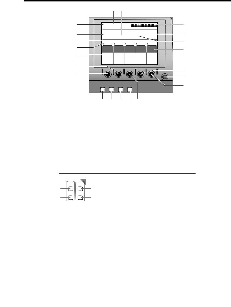
Parts and their functions
Front panel controls
|
POWER |
|
X / Y |
ON |
Pb / Pr |
|
1
OFF
ASPECT |
Z |
H V
2
 3
3
|
SCENE |
EDITOR |
ON HOLD CENTER GRABBER |
|
PATTERN |
9 |
8 7 6 5 4 |
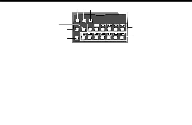
1POWER switch |
5CENTER button |
This is used to switch the AC power on and off. Select “Power” from the “Setup” initial setting screen: “Reset” is selected to establish the default setting when the power is turned ON, and “Preset” is selected to start operation using the same settings which were in effect upon conclusion of the previous operation. When [Demo] is selected, the demo mode is established after the power is turned on. The demo mode can be exited by selecting [Enter].
When the power is off, the operation panel settings are stored in the memory.
Centering is performed when this button is set to ON.
In the case of color settings, the color saturation is set to zero.
In the case of position settings, the pattern is centered.
6HOLD button
The joystick operation is stopped when this button is set to ON. However, even when this button is set to ON, the center button can be used.
Updating to the joystick value occurs when this button is set to OFF.
2Joystick
The joystick is used both as the XY positioner and the controller for the color settings. It is switched as required. It can set X, Y and Z for patterns that can be positioned.
It can also set the color corrector UV white balance and chroma saturation.
It can be used as the position X/Y controller for the selection of the blue background when the chroma keys are set.
3Rotary Z control
This control is used to set the key size Z during the key position settings and the luminance setting Y among the color settings.
4SCENE GRABBER button
When this is set to ON with a specific key pattern, it can paste the image in the key onto the pattern and move it.
<Note>
It is possible to select either the multi-strobe or scene grabber (but not both). Whichever one was selected last takes precedence, and the previously selected effects are canceled.
7ASPECT ratio control
This control is used to set the aspect ratio for key patterns whose aspect ratio can be set. When it is turned in the H direction, the width (horizontal) is increased; when it is turned in the V direction, the height (vertical) is increased.
8Aspect ON button
When this button is at ON, the setting performed by the aspect ratio control takes effect. When it is at OFF, the default aspect ratio (center value) is established.
9EDITOR enable button
Editor enable can enable or disable control using RS422A, and when control is disabled, settings can be performed by manual operations even during editing operations using RS-422A.
When the lamp of this button is lighted (ON), the settings from the editor are accepted; when it is off (OFF), the settings are canceled, and the settings can be performed manually.
6
Parts and their functions
1 2 3
|
|
|
|
PATTERN |
|
|
|
ONE |
DSK |
|
|
|
REV |
WAY |
EFFECTS |
|
|
8 |
LUM |
CHRM EXT |
P in P |
4 |
|
|
|||||
|
7 |
|
|
|
|
|
|
|
|
|
|
|
MIX |
|
|
|
5 |
|
6 |
|
|
|
|
|
|
|
|
|
|
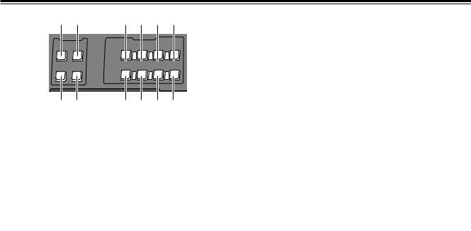
1REV (reverse) button
This button is used to reverse the keys and transition key patterns, reverse the frame in/out, and reverse the chroma key, luminance key, external key and title α key signals.
The button’s lamp flashes with patterns that have no reverse operations, indicating that these patterns cannot be reversed.
2ONE WAY button
At the AB bus setting stage, this button sets the transition pattern to a pattern from one direction.
The button’s lamp flashes with preset bus or program bus or with patterns that have no reverse patterns, indicating that the effects cannot be executed.
6MIX button
This is used to call mix transitions.
7LUM (luminance) key button
This is used to call the luminance key. When it is called, the previous setting is stored in the memory.
8CHRM (chroma) key button
This is used to call the chroma key. When it is called, the previous setting is stored in the memory.
3DSK EFFECTS button
When this button is set to the ON position, the transition pattern and 3D-DVE are used for DSK. ME is set to Diss.
When the DSK effects are ON, the chroma key and luminance key cannot be selected.
This button is set to OFF as the default setting, and some patterns cannot be used for the DSK effects.
<Note>
If DSK-Effects has been set to ON for a pattern which is not supported by DSK using a wipe pattern number, the button’s lamp flashes to indicate that DSK effects cannot be applied.
4Direct key pattern buttons
These buttons are used to call the key patterns directly. With the setup initial settings, key patterns can be set from the default settings to any patterns.
The settings accompanying borders are also stored in the memory for each button.
5Direct transition pattern buttons
These buttons are used to directly call the transition patterns directly. With the setup initial settings, transition patterns can be set from the default settings to any patterns.
The settings accompanying borders are also stored in the memory for each button.
7
Parts and their functions
1 2 |
5 7 9 ; |
|||||
PREVIEW |
|
EFFECTS |
|
|||
ME |
A |
|
|
|
|
|
PRV |
PROG |
|
|
|
|
|
|
|
A |
|
|
|
|
|
|
PROG |
|
|
|
|
|
B |
STILL |
STROBE |
|
VIDEO COLOR |
|
DSK |
EFFECTS EFFECTS |
|||||
PRESET |
|
|
||||
|
|
|
|
|||
|
|
B |
|
|
|
|
|
|
PRESET |
|
|
|
|
|
|
|
|
|
MIX EFFECT |
|
3 4 |
6 8 : < |
|||||
Preview
The controls |
which |
images among |
and A/B |
bus images |
output |
connector on the rear panel.
1ME PRV selector button
This button is used to select ME preview as the image to be output to the preview connector. With transitions, the image of the transition destination can be previewed; with keys, combined images can be previewed.
2A/PROG bus selector button
This button is used to select the A/PROG bus as the image to be output to the preview connector.
3B/PRESET bus selector button
This button is used to select the B/PRESET bus as the image to be output to the preview connector.
4DSK selector button
This button is used to select the DSK combined image as the image to be output to the preview connector.
Effect execution button area
5A/PROG bus / STILL execution button
This button forcibly applies the still effect to the A/PROG bus.
When it is pressed, the A/PROG video effect setting page appears on the LCD screen.
6B/PRESET bus / STILL execution button
This button forcibly applies the still effect to the B/PRESET bus.
When it is pressed, the B/PRESET video effect setting page appears on the LCD screen.
7A/PROG bus / STROBE execution button
This button forcibly applies the strobe effect to the A/PROG bus. The setting is performed as a [Video Effects] setting screen.
When the button is pressed, the A/PROG video effect setting page appears on the LCD screen.
8B/PRESET bus / STROBE execution button
This button forcibly applies the strobe effect to the B/PRESET bus.
When the button is pressed, the B/PRESET video effect setting page appears on the LCD screen. The still and strobe field/frame setting is performed using the time effect settings of [Video Effects].
<Note>
Both still and strobe cannot be selected at the same time. Whichever one was selected last takes precedence. In the case of manual strobe, the effect is applied by pressing the button together with “Shift.”
9A/PROG bus / VIDEO EFFECTS execution button
This applies the mosaic, decay and other video effects set by [Video Effects] to the A/PROG bus.
When the button is pressed, the A/PROG video effect setting page appears on the LCD screen. When it is pressed together with the Shift button, the A/PROG video effect setting page can be displayed on the LCD screen without changing the ON/OFF setting of the effects.
:B/PRESET bus / VIDEO EFFECTS execution button
This applies the mosaic, decay and other video effects set by [Video Effects] to the B/PRESET bus.
When it is pressed together with the Shift button, the A/PROG video effect setting page can be displayed on the LCD screen without changing the ON/OFF setting of the effects.
;A/PROG bus color effect execution button
This applies the white balance, brightness adjustment and other color effects set by [Color Effects] to the A/PROG bus.
When it is pressed together with the Shift key, the A/PROG color effect setting page can be displayed on the LCD screen without changing the ON/OFF setting of the effects.
<B/PRESET bus / COLOR EFFECTS execution button
This applies the white balance, brightness adjustment and other color effects set by [Color Effects] to the B/PRESET bus.
When it is pressed together with the Shift key, the B/PRESET color effect setting page can be displayed on the LCD screen without changing the ON/OFF setting of the effects.
<Note>
Both the color effects and mono effects cannot be selected at the same time. If both are selected, the mono effects always take precedence.
8
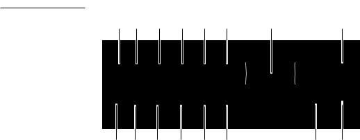
Parts and their functions
Setting panel area
|
2 5 |
|
|
|
||
1 |
POS. X 119 X 107 |
|
3 |
|||
|
Z 235 |
|
|
|
||
4 |
EVENT |
METime |
Pattern |
INT |
7 |
|
00E |
02:00F 2101 Wht |
|||||
8 |
6 |
|||||
Transition |
|
|
||||
9 |
Modify |
|
|
|
: |
|
|
|
|
|
|
||
; |
Pattern |
|
|
|
|
|
Edge |
Hard |
|
|
|
||
|
|
|
|
|||
|
Effects |
Off |
|
Light |
|
|
= |
|
|
On |
|
||
|
|
|
|
? |
||
< |
|
|
|
CONTRAST |
||
|
|
|
|
A |
||
|
|
|
|
|
||
|
INT |
DSK |
AUDIO |
|
@ |
|
|
SET UP VIDEO |
FADE |
EFFECTS |
|
||
|
B C D E > |
|
|
|||
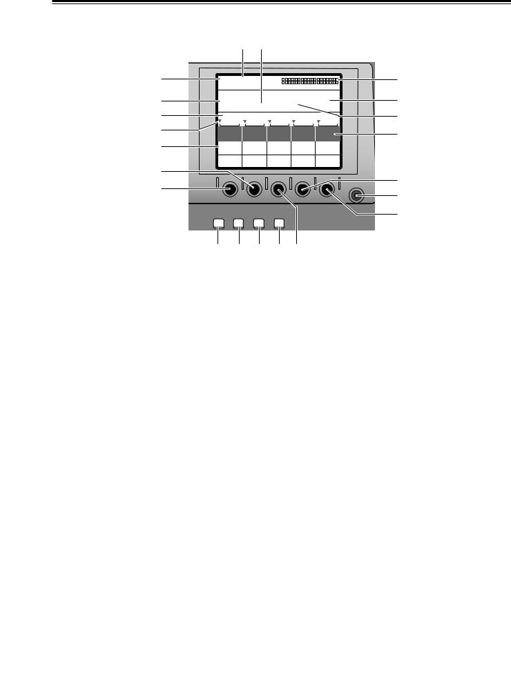
1LCD (liquid crystal) display |
9Rotary control setting position display area |
The effect parameters, time settings and other |
The currently set positions of the rotary 1, 2, 3, 4 and 5 |
information are shown on this display. |
controls are displayed here. |
2Joystick, Z parameter display area |
:Scroll bar |
During positioning, the X/Y/Z parameters are displayed |
This displays the position on the page of the item |
here; during the color settings, the Pb/Pr/Y parameters |
currently displayed. |
are displayed. |
|
3Audio level meter
This indicates the level of the output sound.
4Event number display area
The event numbers are displayed here.
5Time display area
The ME, DSK and FADE transition times are displayed here.
;Item, parameter setting area
The details which are set using the setting pages are switched and displayed here.
The selected settings are displayed negatively, and the parameters can each be changed using the rotary 1, 2, 3, 4 and 5 controls.
<Rotary 1 control
This control is used to set the parameter of a selected item.
6Pattern number display area
The transition and key numbers are displayed here.
7Internal (internally generated) video display area
The settings for the internal video signals are displayed here.
=Rotary 2 control
This control is used to set the parameter of a selected item.
>Rotary 3 control
This control is used to set the parameter of a selected item.
8Setting page display area
The name of the page which has been set by the button operations is displayed here.
?Rotary 4 control
This control is used to set the parameter of a selected item.
@Rotary 5 control
This control is used to set the parameter of a selected item.
9
Parts and their functions
|
2 5 |
|
|
|
||
1 |
POS. X 119 X 107 |
|
3 |
|||
|
Z 235 |
|
|
|
||
4 |
EVENT |
METime |
Pattern |
INT |
7 |
|
00E |
02:00F 2101 Wht |
|||||
8 |
6 |
|||||
Transition |
|
|
||||
9 |
Modify |
|
|
|
: |
|
|
|
|
|
|
||
; |
Pattern |
|
|
|
|
|
Edge |
Hard |
|
|
|
||
|
|
|
|
|||
|
Effects |
Off |
|
Light |
|
|
= |
|
|
On |
|
||
|
|
|
|
? |
||
< |
|
|
|
CONTRAST |
||
|
|
|
|
A |
||
|
|
|
|
|
||
|
INT |
DSK |
AUDIO |
|
@ |
|
|
SET UP VIDEO |
FADE |
EFFECTS |
|
||
|
B C D E > |
|
|
|||
ALCD CONTRAST control |
setting page display) |
This control is used to adjust the |
|
display. |
DSK/fade setting page. |
BSET UP (initial setting page |
(audio effect setting page |
This button displays the initial setting |
|
|
audio effect setting page. |
CINT VIDEO (internal video display) button
This button displays the internal video
EVENT |
AUDIO |
button |
|
RECALL |
EFFECTS |
This button is used to read out events. |
|
ON |
|||
1 |
3 |
||
|
|||
SET |
FOLLOW |
2EVENT SET button |
|
2 |
4 |
||
|
|
This button is used to store events in the memory. |
3AUDIO EFFECTS ON (audio effect execution) button
At the button’s ON setting, the effects which were set on the audio effect setting page are executed.
4AUDIO FOLLOW video button
This button enables the audio to be matched with the video during video ME transition or fading. Its function is supported at the ON position.
ON or OFF is preset for fading on the DSK/fade setting page.
10
Parts and their functions
|
1 |
2 |
|
PHONE |
TIME |
||
MIN |
MAX |
|
4 |
PATTERN |
ME |
DSK |
5 |
FADE |
|||
3 |
|
|
6 |
7 |
8 |
9 |
8 |
4 |
5 |
6 |
9 |
7 |
|
|
|
1 |
2 |
3 |
|
TITLE PLAY |
INT PLAY |
|
CANCEL |
0 . |
SHIFT |
|
|
: ; < = |
|||
1PHONE (headphone volume) control
This control is used to adjust the level of the rear panel headphone (PHONE) output.
The sound of the portion to be faded using the DSK/Fade setting can be monitored before fading so that it can be heard even when AudioFade is used.
The sound is output from the rear panel. Since the audio meter displays the Prog output level, it will remain unchanged even when the headphone level is changed.
2TIME (time setting) rotary control
This control is used to set the ME, DSK and FADE transition times.
3PATTERN (transition/key pattern number setting) button
Set this button to ON to set the pattern numbers using the number keys. At its OFF position, the time can be set using the number keys.
7Number keys 1 to 9
These keys can be used to input numerical values for the event numbers when the event recall button or event setting button is ON, for the pattern numbers when the event recall button or event setting button is OFF and the pattern number setting button is ON, and for the transition times when the pattern number setting button is OFF.
8“+” key
This key is used to increment the event numbers when the event recall button or event setting button is ON, the pattern numbers when the event recall button or event setting button is OFF and the pattern number setting button is ON, and the transition times when the pattern number setting button is OFF.
9“–” key
This key is used to decrement the event numbers when the event recall button or event setting button is ON, the pattern numbers when the event recall button or event setting button is OFF and the pattern number setting button is ON, and the transition times when the pattern number setting button is OFF.
:0 number key
This key is used to input zeros. When it is pressed together with the shift key, the animation in the title memory now selected starts playing.
;Period key
This key is used to enter the seconds when inputting the time.
Example: [2][.][5] > 2 seconds 5 frames
When it is pressed together with the shift key, the internal video movie now selected starts playing.
4ME (ME transition/key transition time) setting button
Set this button to ON to set the time to be applied to the ME transition/key using the time setting rotary control. When the pattern number setting button is OFF, the time can be set using the number keys.
5DSK (DSK transition time) setting button
Set this button to ON to set the time to be applied to DSK using the time setting rotary control.
When the pattern number setting button is OFF, the time can be set using the number keys.
6FADE (fade transition time) setting button
Set this button to ON to set the time to be applied to the FADE using the time setting rotary control.
When the pattern number setting button is OFF, the time can be set using the number keys.
<Shift key
When this key is pressed together with another key, the resulting effect differs from the one produced when the key concerned is pressed on its own.
=Enter key
This key is used to enter numerical values.
When "OK?" appears on the LCD display, press this key to enter the setting.
Entry is canceled when it is pressed together with the shift key.
11
Parts and their functions
1 2 4 6 8 : |
< |
= |
SHIFT |
SOURCE |
SOURCE |
|
1 / 5 |
2 / 6 |
||
|
A / PROG |
SOURCE 3 / 7
|
MIX EFFECTS |
|
FADE |
SOURCE |
INT/EXT |
4 / 8 |
AUTO |
DSK |
|
TAKE |
B / PRESET
1 3 5 7 9 ; |
> ? |
1SHIFT key |
9B/PRESET / SOURCE 4/8 selector button |
This key has the same function as the shift key for the number keys.
2A/PROG /SOURCE 1/5 selector button
This button is used to select source 4 selected by the initial settings for the B/PRESET bus. When it is pressed together with the shift key, source 8 is selected.
This button is used to select source 1 selected by the initial settings for the A/PROG bus. When it is pressed together with the shift key, source 5 is selected.
3B/PRESET / SOURCE 1/5 selector button
This button is used to select source 1 selected by the initial settings for the B/PRESET bus. When it is pressed together with the shift key, source 5 is selected.
4A/PROG / SOURCE 2/6 selector button
This button is used to select source 2 selected by the initial settings for the A/PROG bus. When it is pressed together with the shift key, source 6 is selected.
5B/PRESET / SOURCE 2/6 selector button
This button is used to select source 2 selected by the initial settings for the B/PRESET bus. When it is pressed together with the shift key, source 6 is selected.
6A/PROG / SOURCE 3/7 selector button
This button is used to select source 3 selected by the initial settings for the A/PROG bus. When it is pressed together with the shift key, source 7 is selected.
7B/PRESET / SOURCE 3/7 selector button
This button is used to select source 3 selected by the initial settings for the B/PRESET bus. When it is pressed together with the shift key, source 7 is selected.
:A/PROG / INT/EXT selector button
This button is used to select the image (INT) selected on the internal video setting page for the A/PROG bus. When it is pressed together with the shift key, the external input (EXT) is selected.
;B/PRESET / INT/EXT selector button
This button is used to select the image (INT) selected on the internal video setting page for the B/PRESET bus. When it is pressed together with the shift key, the external input (EXT) is selected.
<Transition lever
This lever enables transitions to be performed manually.
=FADE (fade execution) button
This button enables fade-out into the color set on the [DSK/FADE] setting page.
During execution, its lamp lights; during fade-out, it flashes.
>AUTO TAKE button
This button enables the ME transitions and keys to be transited automatically. During execution, its lamp lights. When it is pressed again during transiting, the transiting stops at the position where it was pressed.
While the transiting is stopped, it flashes. When it pressed again, the transiting resumes.
8A/PROG / SOURCE 4/8 selector button
This button is used to select source 4 selected by the initial settings for the A/PROG bus. When it is pressed together with the shift key, source 8 is selected.
?DSK execution button
This enables DSK which was set on the [DSK/FADE] setting page to be executed.
During execution, its lamp lights; during DSK, it flashes.
12
Parts and their functions
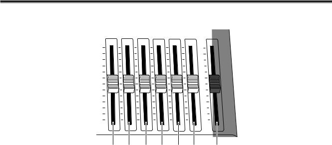
Audio mixer area
SOURCE |
SOURCE |
SOURCE |
SOURCE |
|
MIC / |
MASTER |
1 / 5 |
2 / 6 |
3 / 7 |
4 / 8 |
AUX 1 |
AUX 2 |
|
MAX |
|
|
|
|
|
MAX |
MIN |
MIN |
1 |
2 |
3 |
4 |
5 |
6 |
7 |
1SOURCE 1/5 fader |
|
|
|
4SOURCE 4/8 fader |
||
This fader is used to adjust the audio level of input 1 which was set on the initial setting page; when it is operated together with the shift key, it is used to adjust the audio level of input 5.
The operation of the fader lever takes effect from where the internal level and lever position match or where the higher/lower relationship between them has been reversed when the input has been switched.
2SOURCE 2/6 fader
This fader is used to adjust the audio level of input 2 which was set on the initial setting page; when it is operated together with the shift key, it is used to adjust the audio level of input 6.
The operation of the fader lever takes effect from where the internal level and lever position match or where the higher/lower relationship between them has been reversed when the input has been switched.
This fader is used to adjust the audio level of input 4 which was set on the initial setting page; when it is operated together with the shift key, it is used to adjust the audio level of input 8.
The operation of the fader lever takes effect from where the internal level and lever position match or where the higher/lower relationship between them has been reversed when the input has been switched.
<Note>
The adjusted sounds of 1 to 8 are selected at the cross points and combined.
When [FOLLOW] is ON, the transition is coupled with Video. When [FOLLOW] is OFF, the transition is not coupled with Video. The sounds of both A and B are combined.
The output level can be adjusted using the MASTER fader. The effects that have been set are executed using the Audio Effects ON button.
3SOURCE 3/7 fader
This fader is used to adjust the audio level of input 3 which was set on the initial setting page; when it is operated together with the shift key, it is used to adjust the audio level of input 7.
The operation of the fader lever takes effect from where the internal level and lever position match or where the higher/lower relationship between them has been reversed when the input has been switched.
5AUX 1 fader
This fader is used to set the audio level of input AUX 1.
6MIC/AUX 2 fader
This fader is used to adjust the audio level of the input AUX2 selected on the initial setting page or of MIC (sound selected by Setup).
7MASTER fader
This fader is used to adjust the output level.
It executes the effects which have been set by the Audio Effects ON button.
13
Parts and their functions
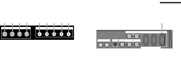
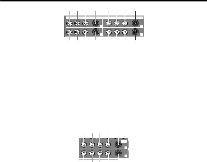
Rear panel connection area
1 2 3 4 |
5 6 7 8 9 |
||
|
EXT IN |
|
SDI |
KEY Y |
P |
P |
IN1 IN2 IN3 IN4 OUT |
|
B |
R |
|
EXT IN (external key input area)
1External key input connector
This connector can be used for key or DSK applications. It can also be used for genlock signal using the settings on the initial setting page.
2External input Y connector
The cross point EXT or DSK Y signal is input to this connector.
The DSK source can be set on the DSK/FADE setting page.
3External input PB connector
The cross point EXT or DSK PB signal is input to this connector.
4External input PR connector
The cross point EXT or DSK PR signal is input to this connector.
<Notes>
≥Non-standard signals are not accepted.
≥Since the input signals do not pass through the frame synchronizers, they must be synchronized with this unit.
58 9 :
|
G/L |
|
AUX IN |
AUDIO OUT 2 |
|
|
1 |
2 |
|
|
|
|
L |
L |
MIC PHONE |
USB ADV-REF PREVIEW |
GPI |
|
|
|
|
|
R |
R |
EDITOR
1 2 3 4 6 7
1MIC input connector
This connector can be set to MIC or AUX 2 on the initial setting page.
2PHONE (headphone) output connector
The headphones are connected to this connector.
3USB interface connector
This connector is used to connect to a personal computer and download files.
4ADV-REF (advanced reference) output connector
This connector outputs the reference signal with advanced vertical phase for source input uses.
5G/L (genlock reference) input connectors
These are loop-through, automatically terminated connectors.
They supply signals to the source VTR or camera and initiate genlock.
They enable genlock for the G/L input or EXTKEY input by making a selection on the initial setting page.
SDI (SDI option area)
5IN1 connector
6IN2 connector
7IN3 connector
8IN4 connector
9OUT connector
The connectors listed above are used when the optional board (AG-YA70) has been installed.
6PREVIEW output connector
The signals selected by the preview selector button are output from this connector.
7GPI input connector
A trigger is applied and a transition is enabled for ME, DSK or fade as selected on the initial setting page. The effect is applied 3 frames later.
8AUX IN (spare) 1 L and R input connectors
AND
9AUX IN (spare) 2 L and R input connectors
These connectors can be used by making a selection on the initial setting page.
:AUDIO OUT 2 L and R output connectors
These are unbalanced audio output connectors.
14
Parts and their functions
1 2 3 |
4 |
5 6 7 |
8 |
||||
|
|
|
VIDEO IN |
|
|
|
|
Y/V |
P /V5 |
P |
YC |
Y/V |
P /V6 |
P |
YC |
|
B |
R |
|
|
B |
R |
|
|
|
|
1 |
|
|
|
2 |
Y/V |
P /V7 |
P |
YC |
Y/V |
P /V8 |
P |
YC |
|
B |
R |
|
|
B |
R |
|
|
|
|
3 |
|
|
|
4 |
|
|
|
|
|
|
AUDIO IN |
|
9 : ; |
< |
= > ? |
@ |
||||
1Composite/component Y input 1 connector |
9Composite/component Y input 3 connector |
||||||
2Composite 5/component PB input 1 connector |
:Composite 7/component PB input 3 connector |
||||||
3Component PR input 1 connector |
|
|
;Component PR input 3 connector |
||||
4YC input 1 connector |
|
|
|
<YC input 3 connector |
|||
5Composite/component Y input 2 connector |
=Composite/component Y input 4 connector |
||||||
6Composite 6/component PB input 2 |
|
|
|
|
|
8/component PB input 4 connector |
|
7Component PR input 2 connector |
|
|
|
|
|
PR input 4 connector |
|
8YC input 2 connector |
|
|
|
|
|
|
connector |
1 2 3 4 5
V |
Y |
PB |
P |
YC |
VIDEO |
R |
OUT |
|
|
|
1 |
V Y |
P |
P |
YC |
|
B |
R |
|
|
|
|
2 |
|
|
|
AUD |
6 7 8 9 |
: |
||
1Composite output 1 connector |
|
6Composite output 2 connector |
|
2Component Y output 1 connector |
|
7Component Y output 2 connector |
|
3Component PB output 1 connector |
|
8Component PB output 2 connector |
|
4Component PR output 1 connector |
|
9Component PR output 2 connector |
|
5YC output 1 connector |
|
:YC output 2 connector |
|
15
Parts and their functions
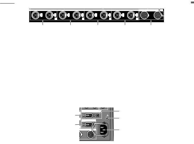
|
|
|
|
AUDIO IN |
|
|
|
|
AUDIO OUT 1 |
L |
R |
L |
R |
L |
R |
L |
R |
L |
R |
1 |
2 |
3 |
4 |
1 |
2 |
3 |
4 |
5 |
1Analog audio 1 input connectors |
|
4Analog audio 4 input connectors |
||
The audio signals supplied to these connectors are input to the cross point selected on the initial setting page.
The audio signals supplied to these connectors are input to the cross point selected on the initial setting page.
2Analog audio 2 input connectors |
5Analog audio output connectors |
The audio signals supplied to these connectors are input to the cross point selected on the initial setting page.
3Analog audio 3 input connectors
The audio signals supplied to these connectors are input to the cross point selected on the initial setting page.
O |
EDITOR |
RS422 |
2 |
1 |
|
SIGNAL |
|
|
|
GND |
|
|
|
|
|
|
|
RS232C |
3 |
|
TALLY |
~AC IN |
|
|
|
||
4 |
|
|
|
2 |
|
|
5 |
AUDIO OUT 1 |
|
||
|
R |
|
|
1EDITOR interface connector (9-pin)
This connector is used to connect the unit with an RS422A or RS-232C controller.
4TALLY output connector
The rear panel tally is for the cross point 1, 2, 3, 4, 5, 6, 7 or 8 output.
The connector used by the cross point is turned ON.
2RS-422A/RS-232C selector switch
This is used to switch between the RS-422A and RS- 5AC IN power socket 232C control protocols.
3SIGNAL GND (ground) terminal
16
External interfaces
This unit comes with three connectors to support four external interfaces: a GPI input connector, RS-422A/RS-232 (9-pin) connector and a Tally output connector. Select the connector that suits the editing controller model used.
∫ GPI (general purpose interface)
∫ RS-232C
This enables the unit to be controlled using a personal computer. All of the unit’s functions with the exception of AUX 1 and AUX 2 can be set.
≥ Connection of conversion cable
This enables the use of auto takes with the GPI output of |
RS-232C |
AG-MX70 |
||
the external controller. At the fall of the GPI signal, wipe/mix |
25-pin |
9-pin |
||
set on the panel or DSK or Fade is executed. |
1 |
TXD |
1 |
SPARE |
∫ RS-422A |
3 |
RXD |
2 |
RXD |
4 |
RTS |
3 |
TXD |
|
This enables the AG-A850 external editing controller to be |
5 |
CTS |
4 |
DTR |
connected to the unit and the VTR to be controlled from a |
6 |
DSR |
5 |
SIG.G |
remote location. |
7 |
SIG.G |
6 |
DSR |
≥ Functions that can be controlled from the AG-A850 |
20 |
DTR |
9 |
SPARE |
±Wipe settings |
|
|
|
[DCE CONNECTION] |
|
|
|
|
|
±Mixing
Use the above conversion with the 9-pin straight cable
±Auto take time and auto fade time settings
as well.
±Downstream key fade-in and fade-out
±Cross point source 1/source 2 (source 2/source 3 <Notes> Editing using the RS-422A, RS-232 and GPI
or source 3/source 4) switching
(Cross mode switching is performed by the RS- 422A/RS-232C selector switch on the rear panel. Support for the editing controller is shown below.)
≥Connections
1)Set the RS-422A/RS-232C selector switch to “RS-422A.”
2)Connect the connecting cable from the AG-A850 to the editing controller connector on this unit.
3)The pin layout of the editing controller connector is shown below.
interface connectors
≥The commands are received and then executed 3 frames later.
≥If, while the 3D optional board is installed, the 1-Frame Dly mode has been selected by the system 1 settings (see page 56) on the “Setup” initial setting screen, the pictures and sound from the source are always output with a 1-frame delay.
≥When selecting a DVE pattern, set the transition time to more than 2 frames. No guarantees are made for frame accuracy if the time setting is lower than this.
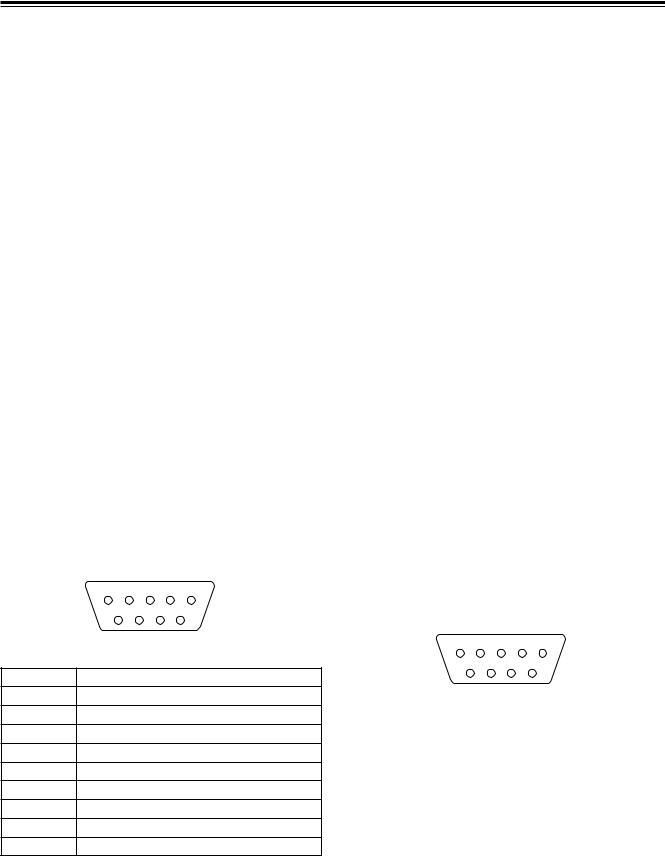
5 |
4 |
3 |
2 |
1 |
|
9 |
8 |
7 |
6 |
|
Connector (9P) |
|||
Pin No |
|
|
|
Signal |
1 |
|
|
FRAME GROUND |
|
2 |
|
|
TRANSMIT A |
|
3 |
|
|
|
RECEIVE B |
4 |
|
|
RECEIVE COMMON |
|
5 |
|
|
|
SPARE |
6 |
|
TRANSMIT COMMON |
||
7 |
|
|
TRANSMIT B |
|
8 |
|
|
|
RECEIVE A |
9 |
|
|
FRAME GROUND |
|
∫ Tally
An open connector is provided for outputting the tally lamp signals.
5 |
4 |
|
3 |
2 |
1 |
|
|
|
9 |
8 |
7 |
|
6 |
|
|
Connector (9P) |
||||
|
|
|
|
|
|
|
Pin No |
|
|
|
|
|
Signal |
|
|
|
||||
1 |
|
Output for cross point 1 |
||||
|
|
|
||||
2 |
|
Output for cross point 2 |
||||
|
|
|
||||
3 |
|
Output for cross point 3 |
||||
|
|
|
||||
4 |
|
Output for cross point 4 |
||||
|
|
|
||||
5 |
|
Output for cross point 5 |
||||
|
|
|
||||
6 |
|
Output for cross point 6 |
||||
|
|
|
||||
7 |
|
Output for cross point 7 |
||||
|
|
|
||||
8 |
|
Output for cross point 8 or EXT |
||||
|
|
|
|
|
|
|
9 |
|
|
|
|
|
GND |
|
|
|
|
|
|
|
17

System Diagram
By connecting cameras, VTRs and other video components, this unit can digitally process the video signals of these components.
Example 1 Live application (1)
|
|
CPST |
|
|
|
|
|
Y, Pb, Pr |
|
|
|
|
Box camera |
|
KEY |
ADV-REF |
|
|
|
|
|
||
|
|
|
(Genlock |
|
|
|
|
|
|
|
|
|
|
SDI |
enabled as |
AG-MX70 |
|
Through connection |
|
(Video) |
genlock |
|
|
|
|
|
|||
|
|
source) |
|
|
|
|
|
|
|
|
|
|
Box camera |
|
Y, Pb, Pr |
|
|
|
|
SDI |
SDI IN2 |
|
SDI OUT |
|
|
|
|
||
Through connection |
|
(Video) |
SDI IN3 |
|
|
|
|
|
|||
|
Box camera |
|
SDI IN4 |
|
|
|
|
|
|
|
|
|
|
SDI |
MIC |
USB |
|
|
|
|
|
|
|
Termination |
|
(Audio/Video) |
|
|
|
VTR |
|
|
|
|
|
|
|
|
|
|
|
|
|
|
Microphone |
|
|
|
|
|
|
PC (with MX-Navi already |
|
|
|
|
|
installed) |
|
Example 2 Live application (2) |
|
|
|
|
|
|
|
|
|
|
Signal |
|
|
|
|
|
generator |
|
|
CPST |
|
|
|
|
|
Y, Pb, Pr |
|
Through connection |
|
Termination |
Box camera |
|
|
|
|
|
|
|
|
||
|
|
|
|
G/L |
|
|
|
|
|
|
|
|
|
|
|
|
(Genlock enabled |
|
|
SDI |
|
ADV-REF |
as genlock source) |
|
|
|
|
||
|
|
|
|
|
|
Through connection |
|
(Video) |
|
|
|
|
|
KEY |
|
|
|
|
|
|
|
|
|
|
Box camera |
Y, Pb, Pr |
AG-MX70 |
|
|
||
|
SDI |
SDI IN2 |
SDI OUT |
|
|
||
Through connection |
(Video) |
SDI IN3 |
|
|
|
SDI IN4 |
|
Box camera
|
MIC |
USB |
|
SDI |
|
Termination |
(Audio/Video) |
|
VTR |
|
Microphone
PC (with MX-Navi already installed)
18
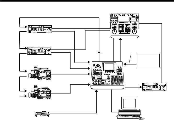
System Diagram
Example 3 Editing application
connection |
Through |
connection |
Through |
connection |
Through |
Termination
RS-422A
VTR |
SDI |
|
|
Editing |
|
|
|
controller |
|||
(Audio/Video) |
|
Through connection |
|||
|
|
|
genlock source) |
||
|
|
|
|
G/L *2 |
|
|
RS-422A |
|
|
(Genlock enabled as |
|
VTR |
SDI |
ADV |
|
|
|
(Audio/Video) |
RS-422A |
Signal |
|||
|
REF *1 |
||||
|
|
SDI IN1 |
|
generator |
|
|
|
|
|
||
|
|
SDI IN2 |
|
|
|
|
|
SDI IN3 |
|
AG-MX70 |
|
|
SDI |
|
|
||
|
|
|
|
||
|
(Audio/Video) |
|
|
RS-422A |
|
Video camera |
|
SDI IN4 |
|
||
|
|
SDI OUT |
|||
|
|
|
|
||
|
SDI |
AUX1/AUX2 |
USB |
VTR |
|
|
|
||||
|
|
|
|
||
|
(Audio/Video) |
|
|
|
Video camera
Analog audio signals
CD player, etc.
PC (with MX-Navi already installed)
*1: Connection of the ADF REF signal is not absolutely essential but when this signal has been connected, “StillOff” can be selected by the bus setting (see page 56) on the “Setup” initial setting screen and input can be switched directly using the cross point button.
*2: ADV REF can also be used as an alternative to the G/L loop-through signal as the sync signal supplied to the AG-A850 editing controller.
19

Power supply and backup
The operation panel settings are stored in the memory when the power is turned off.
The default settings are established when the power is turned back on by selecting [Power] > [Reset] on the [Setup] initial setting screen, and the system is started from the settings which were established at the completion of the previous session by selecting [Power] > [Preset]. If [Demo] has been selected on the [Setup] panel, the demonstration mode is established when the power is turned on.
Select [Reset] or [Preset] on the [Setup] panel from the demonstration mode to restart the system. The demonstration mode can be exited using [Enter].
The panel settings, setup settings and their files, key learn settings and event memory data are saved. These settings and data are backed up by the flash memory even when the power is turned off.
Setting panel screen
The unit’s various functions are adjusted on the setting panel screen. This screen is basically configured as follows.
≥Displayed at the top level of the screen are the joystick XY and rotary Z values and the audio meter.
≥Displayed at the second level of the screen from the top are the event number, transition time, pattern number and internal video setting.
≥Displayed at the third level of the screen from the top are the title of the menu on the display and the item setting ranges.
≥The settings are displayed from the center down. The settings of four items are displayed per page. If there are more than four item settings, they can be scrolled and displayed using the rotary 1 or 2 control. Two lines are allocated to each item, and 7 or so alphanumerics are displayed per item. In some cases, abbreviations are used for the displays.
≥The display of selected setting item is highlighted in reverse video.
≥Selected setting items are returned to their default settings using [Shift] + [.].
[INTVideo] internal video setting screen
Wash Pb 128 Pr 128 |
|
|
|
|
|
|
|
|
|
|
|
|
|
|
|
Wht |
|
|
|
|
|
|
|
|
|
|
|
|
|
|
|
|
|||
Y 128 |
|
|
|
|
|
|
|
|
|
|
|
|
|
|
|
||
|
|
|
|
|
|
|
|
|
|
|
|
|
|
|
Yelw |
||
|
|
|
|
|
|
|
|
|
|
|
|
|
|
|
|||
|
|
|
|
|
|
|
|
|
|
|
|
|
|
|
|
|
|
Event |
ME Time |
Pattern |
|
|
|
INT |
|||||||||||
|
|
|
|
Cyan |
|||||||||||||
00E |
10:00F |
3015 |
|
Blue |
|
||||||||||||
|
|
Gren |
|||||||||||||||
|
|
|
|
|
|
|
|
|
|
|
|
|
|
|
|
|
Mgt |
INT Video |
|
|
|
Grade Pos 80 |
|
Red |
|||||||||||
|
|
|
|
Blue |
|||||||||||||
|
|
|
|
|
|
|
|
|
|
|
|
|
|
|
|
|
|
Back |
Color |
Level |
|
Pattern |
|
|
Grade |
||||||||||
|
|
|
|
Blk |
|||||||||||||
Matte |
White |
|
255 |
|
H1 |
0 |
|
||||||||||
|
|
|
Cst1 |
||||||||||||||
|
|
|
|
|
|
|
|
|
|
|
|
|
|
|
|
|
|
Color |
|
|
|
|
|
|
|
|
|
|
|
|
|
|
|
|
Cst2 |
Bar |
|
|
|
|
|
|
|
|
|
|
|
|
|
|
|
|
|
|
|
|
|
|
|
|
|
|
|
|
|
|
|
|
|
CL Br |
|
|
|
|
|
|
|
|
|
|
|
|
|
|
|
|
|
|
|
|
|
|
|
|
|
|
|
|
|
|
|
|
|
|
|
|
|
Memory |
Page |
Frame |
|
|
|
|
Mode |
|
St 1-30 |
||||||||
|
1 |
|
1F |
Field |
|
|
|
|
|
Write |
|
Mv 1-30 |
|||||
|
|
|
|
|
|
|
|
|
|
|
|
|
|
|
|
|
|
R1 |
R2 |
R3 |
|
R4 |
|
|
|
|
|
|
R5 |
|
|
||||
|
|
|
|
|
|
|
|
|
|||||||||
The internal video settings are performed on this screen.
This menu is selected when the INTVideo button below the LCD display is pressed. It is not selected using INT at a crosspoint. While these settings are performed, the color setting mode is established for joystick XYZ and rotary Z control. The color set appears at the top right.
Setting items
[Back Matte], [Color Bar] and [Memory] are selected using the rotary 1 control.
20
[INTVideo] internal video setting screen
When [Back Matte] has been selected
The joystick XY and rotary Z control displays are set to Wash, and the wash color that is the companion color for gradation is set.
The joystick [X][Y] and rotary [Z] display change to [Pb], [Pr] and [Y], and the color can be set. [Pb][Pr] can be set to any
value from 0 to 255 and [Y] to any value from 16 to 255 but only when [Custom1] or [Custom2] has been selected using |
|||||||||||||||
rotary 2 control. |
|
|
|
|
|
|
|
|
|
|
|
|
|
|
|
Colors are selected using the rotary 2 control. There are 10 |
R1 |
|
R2 |
|
R3 |
|
R4 |
|
R5 |
||||||
choices: White, Yellow, Cyan, Green, Magenta, Red, Blue, |
|
|
|
|
|||||||||||
|
|
|
|
|
|
|
|
|
|
|
|
|
|
||
Black, Custom1 and Custom2. |
Back |
|
Color |
|
Level |
|
Pattern |
|
Grade |
|
|||||
Matte |
|
White |
255 |
|
|
H1 |
0 |
|
|
||||||
The color level (Y level for White) is set using the rotary 3 |
|
|
|
|
|
||||||||||
|
|
|
|
|
|
|
|
|
|
|
|
|
|
||
control. |
When [Custom1] or [Custom2] has been selected, |
|
|
|
|
|
|
|
|
|
|
|
|
|
|
|
|
White |
|
|
Level |
|
|
Off |
|
0 - 255 |
|
||||
either Back Matte or Wash is set. |
|
|
Yellow |
|
|
0 - 255 |
|
|
H1 |
|
|
|
|
|
|
[Pattern] (gradation pattern) is set using the rotary 4 control. |
|
|
|
|
|
|
|
|
|
|
|
||||
|
|
Cyan |
|
|
|
|
|
H2 |
|
|
|
|
|
||
|
|
|
|
|
|
|
|
|
|
|
|
||||
There are the following nine choices. |
|
|
|
|
Set |
|
|
|
|
|
|
|
|||
|
|
Green |
|
|
|
|
H3 |
|
|
|
|
|
|||
|
|
|
|
|
|
BackM |
|
|
|
|
|
|
|
||
[Off] |
: No gradation |
|
|
Magenta |
|
|
|
|
V1 |
|
|
|
|
|
|
|
|
|
|
Wash |
|
|
|
|
|
|
|
||||
[H1] |
: Horizontal gradation 1 |
|
|
Red |
|
|
|
|
V2 |
|
|
|
|
|
|
|
|
|
|
|
|
|
|
|
|
|
|
||||
|
|
|
|
|
|
|
|
|
|
|
|
||||
[H2] |
: Horizontal gradation 2 |
|
|
Blue |
|
|
|
|
|
V3 |
|
|
|
|
|
[H3] |
: Horizontal gradation 3 |
|
|
Black |
|
|
|
|
|
Diag1 |
|
|
|
|
|
[V1] |
: Vertical gradation 1 |
|
|
Custom1 |
|
|
|
|
|
Diag2 |
|
|
|
|
|
[V2] |
: Vertical gradation 2 |
|
|
Custom2 |
|
|
|
|
|
|
|
|
|
|
|
|
|
|
|
|
|
|
|
|
|
|
|
|
|||
[V3] |
: Vertical gradation 3 |
|
|
|
|
|
|
|
|
|
|
|
|
|
|
|
|
|
|
|
|
|
|
|
|
|
|
|
|
||
[Diag1] : Diagonal gradation 1 [Diag2] : Diagonal gradation 2
The [Grade] combined gradation level is set using the rotary 5 control. Any value from 0 to 255 can be set. The gradation position is set using [Shift] + rotary 5 control.
When [Custom1, 2] has been selected
The rotary 3 control is used to select whether BackM (back matte) or Wash is to be set using the joystick. With Set BackM, the joystick XY and rotary Z control at the top of the screen appear as “Matte,” and with Set Wash, they appear as “Wash,” enabling the respective colors to be adjusted.
The default color for Custom1 and Custom2 is black.
R1 |
R2 |
|
R3 |
|
R4 |
|
R5 |
|||
|
|
|
|
|
|
|
|
|
|
|
Black |
Color |
|
Set |
|
Pattern |
|
Grade |
|||
Matte |
Custom1 |
|
BackM |
|
H1 |
0 |
|
|||
|
|
|
|
|
|
|
|
|
|
|
|
|
|
|
|
|
|
|
|
|
|
|
|
|
Set |
|
|
Off |
|
0 - 255 |
|
|
|
|
|
BackM |
|
|
H1 |
|
|
|
|
|
|
|
Wash |
|
|
H2 |
|
|
|
|
|
|
|
|
|
|
H3 |
|
|
|
|
|
|
|
|
|
|
V1 |
|
|
|
|
|
|
|
|
|
|
V2 |
|
|
|
|
|
|
|
|
|
|
V3 |
|
|
|
|
|
|
|
|
|
|
Diag1 |
|
|
|
|
|
|
|
|
|
|
Diag2 |
|
|
|
|
|
|
|
|
|
|
|
|
|
|
|
21

[INTVideo] internal video setting screen
When [Memory] has been selected
Described below are the write and preview procedures for “Still” (still picture) or “Movie” (moving picture). It is possible to set the number of frames (number of pages) that can be used to a maximum of 30 (NTSC) or 26 (PAL). However, if pages are allocated to titles, the number of pages will be reduced by the equivalent amount. The page allocation can be changed on the “Setup” initial setting screen.
≥ Write procedure |
When Frame = 1 |
|
|
|
|
|
|
|
|
|
||||
Use the rotary 5 control to set the mode to “Write.” |
|
R1 |
|
R2 |
|
R3 |
|
R4 |
|
R5 |
||||
|
|
|
|
|
|
|
|
|
|
|
|
|
|
|
|
Memory |
|
Page |
|
Frame |
|
|
|
|
Mode |
||||
Use the rotary 2 control to select the page on which the |
|
|
|
|
|
|
|
|||||||
|
|
1 |
|
1 |
|
|
Field |
|
Write |
|||||
images are to be written. |
|
|
|
|
|
|
||||||||
|
|
|
|
|
|
|
|
|
|
|
|
|
|
|
Use the rotary 3 control to set the number of frames to be |
|
|
|
|
|
|
|
|
|
|
|
|
|
|
|
|
|
1 - 30/26 |
|
|
1 - 30/26 |
|
|
Field |
|
|
Write |
|
|
written. Set 1 as the number of frames for Still writing and |
|
|
|
(NTSC/PAL) |
|
|
(NTSC/PAL) |
|
|
Frame |
|
|
Preview |
|
set a number greater than 1 for Movie writing. |
|
|
|
|
|
|
|
|
|
|
|
|
Exit |
|
|
|
|
|
|
|
|
|
|
|
|
||||
Check the image to be written at the Prog output, and |
|
|
|
|
|
|
|
|
|
|
|
|
|
|
|
|
|
|
|
|
|
|
|
|
|
|
|
|
|
when the image to be written appears, write it using |
When Frame > 1 |
|
|
|
|
|
|
|
|
|
||||
“Enter.” In the case of Movie, the images are written |
|
R1 |
|
R2 |
|
R3 |
|
R4 |
|
R5 |
||||
consecutively from the page designated by the rotary 2 |
|
|
|
|
|
|||||||||
|
|
|
|
|
|
|
|
|
|
|
|
|
|
|
control up to the page equivalent to the number of frames |
|
Memory |
|
Page |
|
Frame |
|
|
|
|
Mode |
|||
designated by the rotary 3 control. Any existing data will |
|
|
1 |
|
|
5F |
|
Repeat |
|
Write |
||||
be deleted in the process of image writing. |
|
|
|
|
|
|
|
|
|
|
|
|
|
|
|
|
|
|
|
|
|
|
|
|
|
|
|
|
|
|
|
|
1 - 30/26 |
|
|
1 - 30/26 |
|
|
Repeat |
|
|
Write |
|
|
|
|
|
|
|
|
|
|
|
|
|
||||
≥ Preview procedure |
|
|
|
(NTSC/PAL) |
|
|
(NTSC/PAL) |
|
|
Once |
|
|
Preview |
|
|
|
|
|
|
|
|
|
|
|
|
|
Exit |
|
|
|
|
|
|
|
|
|
|
|
|
|
|
|
||
Use the rotary 5 control to set the mode to “Preview.” |
|
|
|
|
|
|
|
|
|
|
|
|
|
|
|
|
|
|
|
|
|
|
|
|
|
|
|
|
|
|
|
|
|
|
|
|
|
|
|
|
|
|
|
|
Use the rotary 2 control to select the page on which the |
|
|
|
|
|
|
|
|
|
|
|
|
|
|
images are to be previewed. To preview Still, use the |
|
|
|
|
|
|
|
|
|
|
|
|
|
|
rotary 4 control to select “Field” output or “Frame” output. |
|
|
|
|
|
|
|
|
|
|
|
|
|
|
To preview Movie, use the rotary 3 control to set the |
|
|
|
|
|
|
|
|
|
|
|
|
|
|
number of frames to be previewed and the rotary 4 control |
|
|
|
|
|
|
|
|
|
|
|
|
|
|
to select “Repeat” (repeat) playback or “Once” (once-only) |
|
|
|
|
|
|
|
|
|
|
|
|
|
|
playback. If a value exceeding the number of frames |
|
|
|
|
|
|
|
|
|
|
|
|
|
|
written has been set by the rotary 3 control, the setting will |
|
|
|
|
|
|
|
|
|
|
|
|
|
|
be ignored. |
|
|
|
|
|
|
|
|
|
|
|
|
|
|
Start the preview using “Enter.” Even when the page selected by the rotary 2 control is midway through the Movie, the Movie is played back from its beginning.
If the settings are acceptable, use the rotary 5 control to set the mode to “Exit”, then enter the settings using “Enter.” The page set is recalled by the “INTVideo” button and played back.
Even when another “Matte” or “CustomColor” selection has been set using “INTVideo” upon completion of the settings, the images previously stored in the memory can be read by selecting “Memory” again but they will be cleared after the power is turned off.
The playback trigger is applied using “Shift” + “.”.
The “Grade” setting which was set by “BackMatte” also takes effect for “Memory.”
<Note>
Images cannot be written during Movie playback. If images are to be written, first set [Mode] to [Exit] and press the [Enter] button to exit Movie playback, and then proceed.
22
[Color Effects] setting screen
Color |
Pb 128 |
Pr 128 |
|
|
|
|
|
|
|
|
|
|
|
|
|
|
|
|
|
|
|
|
|
|
|||
Effect |
C Gain |
128 |
|
|
|
|
|
|
|
|
|
|
|
|
|
|
|
|
|
|
|
|
|
|
|||
|
|
|
|
|
|
|
|
|
|
|
|||
|
|
|
|
|
|
|
|
|
|
|
|
|
|
Event |
ME Time |
Pattern |
|
|
INT |
||||||||
00E |
10:00F |
3015 |
Blue |
||||||||||
Color Effects |
|
|
|
|
ch A |
|
|
Y Setup |
Y Gain |
|
Pb |
|
Pr |
|
C Gain |
128 |
|
128 |
|
128 |
|
128 |
128 |
|
|
|
|
|
|
|
|
R1 |
R2 |
|
|
R3 |
R4 |
R5 |
|
This menu is selected using the A or B bus [Color Effects] button. If the status of the [Color Effects] button is not to be changed, press the [Color Effects] button of the bus to be set while holding down the [Shift] key.
Settings can be performed separately for the A bus and B bus. Preview is set to A by pressing the [Color Effects] button for A. Preview is set to B by pressing the [Color Effects] button for B.
The Y setup [0 to 255] can be set using the rotary 1 control. The default setting is 128.
The Y gain [0 to 255] can be set using the rotary 2 control (0dB=0). The default setting is 128.
The Pb and Pr color balance can be set using the joystick’s X direction (for adjusting Pb) and rotary 3 control or using the joystick’s Y direction (for adjusting Pr) and rotary 4 control, and the chroma gain can be set using the rotary Z and rotary 5 controls.
At this time, the XYZ display is switched to Pb/Pr/C Gain.
Using transition pattern numbers 200 to 211, 215 to 220 and 222, effects are applied to the B or Preset bus using the settings established for this channel, and the pattern is changed to MIX (56).
<Notes>
≥In the case of pattern numbers 221, 222, 1068 and 1069, color effects can be applied to the B channel and transitions can be initiated. When this is done, the pattern is changed to MIX (56). (With the A bus/B bus)
With the preset bus/program bus, the effects are applied to preset, and they are turned off by setting the reverse button to ON.
≥Color effects cannot be applied to the INT EXT inputs.
23
[Video Effects] setting screen
Pos. X |
128 |
Y 128 |
|
|
|
|
|
|
|
|
|
|
|
|
|
|
|
|
|
|
|
|
|
|
|
|
|
|
|
|
|
||||
Z |
128 |
|
|
|
|
|
|
|
|
|
|
|
|
|
|
|
|
|
|
|
|
|
|
|
|
|
|
|
|
|
|
|
|||
|
|
|
|
|
|
|
|
|
|
|
|
|
|
|
|||
|
|
|
|
|
|
|
|
|
|
|
|
|
|
|
|
||
Event |
|
|
ME Time |
Pattern |
|
|
|
INT |
|||||||||
00E |
10:00F 3015 |
|
Blue |
||||||||||||||
Video Effects |
|
|
|
|
|
|
ch A |
||||||||||
|
|
|
|
|
|
|
|
|
|
|
|
|
|
|
|
|
|
Mosaic |
|
|
|
|
|
Size |
|
|
|
|
|
|
|
|
|
|
|
|
|
|
Off |
|
XY |
|
0 |
|
|
|
|
|
|
|
|
|
|
|
|
|
|
|
|
|
|
|
|
|
|
|
|
|
|
|
|
Defocus |
|
|
|
Level |
|
|
|
|
|
|
|
|
|
|
|
|
|
|
|
|
Off |
|
0 |
|
|
|
|
|
|
|
|
|
|
|
|
|
|
|
|
|
|
|
|
|
|
|
|
|
|
|
|
|
|
Mono |
|
|
|
|
|
|
|
|
|
|
|
|
|
|
|
|
|
|
|
|
Off |
|
|
|
|
|
|
|
|
|
|
|
|
|
|
|
|
|
|
|
|
|
|
|
|
||||||||
Time |
|
|
|
|
|
Screen |
|
|
Time |
||||||||
Effects |
|
|
Off |
Field |
|
1 |
|
|
|
|
|
|
10F |
||||
|
|
|
|
|
|
|
|
|
|
|
|
|
|
|
|
|
|
Decay |
|
|
|
Time |
|
|
|
|
|
|
|
|
|
|
|
|
|
|
|
|
Off |
|
16 |
|
|
|
|
|
|
|
|
|
|
|
|
|
|
|
|
|
|
|
|
|
|
|
|
|
|
|
|
|
|
Paint |
|
|
|
Level |
|
|
|
|
|
|
|
|
|
|
|
|
|
|
|
|
Off |
|
4 |
|
|
|
|
|
|
|
|
|
|
|
|
|
|
|
|
|
|
|
|
|
|
|
|
|
|
|
|
|
|
Nega |
|
Y |
|
C |
|
|
|
|
|
|
|
|
|
|
|
|
|
|
|
|
Off |
|
Off |
|
|
|
|
|
|
|
|
|
|
|
|
|
|
|
|
|
|
|
|
|
|
|
|
|
|
|
|
|
|
Mirror |
|
H |
|
V |
|
|
|
|
|
|
|
|
|
|
|
|
|
|
|
|
Off |
|
Off |
|
|
|
|
|
|
|
|
|
|
|
|
|
|
|
|
|
|
|
|
|
|
||||||||
3D |
|
|
|
Level |
|
Time |
|
|
Width |
||||||||
|
|
|
Ripple |
|
0 |
|
16 |
1 |
|||||||||
|
|
|
|
|
|
|
|
|
|
|
|
|
|
|
|
|
|
R1 |
|
|
R2 |
R3 |
|
R4 |
|
|
|
|
|
|
R5 |
||||
Channel display
Scrolled display
This menu is selected using the A or B bus [Video Effects] button. If the status of the [Video Effects] button is not to be changed, press the [Video Effects] button of the bus to be set while holding down the [Shift] key. Settings can be performed separately for the A bus and B bus.
At this time, the bus to be set is automatically output to Preview.
The following video effects can be selected and set using the rotary 1 control: [Mosaic], [Defocus], [Mono], [Time Effects], [Decay], [Paint], [Nega], [Mirror] and [3D]. [OFF], [Ripple], [Multi] or [Spark] can be selected for 3D.
<Note>
Video effects cannot be applied to the INT EXT inputs.
24
[Video Effects] setting screen
[Mosaic] setting
Select [On] or [Off] for this effect using the rotary 2 control. The default setting is [Off].
Select [XY] (both horizontal and vertical), [X] (horizontal only) or [Y] (vertical only) using the rotary 3 control.
Set the size using the rotary 4 control. Any setting from 0 to 30 can be set for Size, and the setting can be changed in 2- step increments. The default setting is 8.
This level setting is used for the level of transition numbers 1001, 1002 and 1003 (200, 201 and 202).
[Defocus] setting
Select [On] or [Off] for this effect using the rotary 2 control. The default setting is [Off].
Select level 0 to 7 using the rotary 3 control. The default setting is 2.
This level setting is used for the level of transition number 1004 (203). It cannot be made to take effect at the same time as a 2-dimensionally compressed pattern.
<Note>
R1 |
R2 |
|
R3 |
|
R4 |
|
|
R5 |
|
|
|
|
|
|
|
|
|
|
|
Mosaic |
|
|
|
|
|
Size |
|
|
|
|
Off |
|
XY |
|
|
8 |
|
|
|
|
|
|
|
|
|
|
|
|
|
|
|
|
|
|
|
|
|
|
|
|
|
|
X |
|
0 - 30 |
|
|
|
|
|
|
|
Y |
|
|
|
|
|
|
|
|
|
XY |
|
|
|
|
|
|
|
|
|
|
|
|
|
|
|
|
R1 |
R2 |
|
R3 |
|
|
R4 |
R5 |
|
|
|
|
|
|
|
|
Defocus |
|
|
Level |
|
|
|
|
|
Off |
|
|
2 |
|
|
|
|
|
|
|
|
|
|
|
|
|
|
|
|
|
|
|
|
|
0 - 7 |
|
|
|
|
Either [Mosaic] or [Defocus] can be selected. The effect selected last takes precedence, and the previously selected effect is canceled.
[Mono] (monochrome) setting
Select [On] or [Off] for this effect using the rotary 2 control. The default setting is [Off].
This effect takes precedence over the setting initiated by [Color Effects].
R1 |
R2 |
R3 |
R4 |
R5 |
Mono
Off
On
Off
25

[Video Effects] setting screen
[Time Effects] still/strobe setting
Select the still or strobe effect with Video Effects ON using the rotary 2 control.
≥When [Off] has been selected The regular screen is output.
≥When [Still] has been selected
Either [Field] or [Frame] is selected as the type using the rotary 3 control. The default setting is [Field].
≥ When [Strobe] has been selected
Set the number of strobe screens and the repeat operation using the rotary 4 control. The default setting is 1.
Select the strobe time setting from 2 to 124 using the rotary 5 control. The default setting is 20. The time setting can be changed in 2-step increments.
Select @4 to @16 for a once-only still operation. Select R4 to R16 for repeat operations. The number denotes the number of screens. At the Manual setting, the screen can be stopped by pressing the cross point [Strobe] button with the [Shift] key. This time setting is used for the level of transition numbers 1062, 1063, 1064 and 1065 (215, 216, 217 and 218). Still and strobe (including multi strobe) cannot be made to take effect at the same time as a 2-dimensionally compressed pattern.
<Notes>
R1 |
|
R2 |
|
R3 |
|
R4 |
|
R5 |
||||
|
|
|
|
|
|
|
|
|
|
|
|
|
Time |
|
|
|
|
|
|
|
Screen |
|
Time |
||
Effects |
|
Still |
|
Field |
1 |
|
|
10F |
||||
|
|
|
|
|
|
|
|
|
|
|
|
|
|
|
|
|
|
|
|
|
|
|
|
|
|
|
|
Off |
|
|
Field |
|
|
1 |
|
|
2 - 124 |
|
|
|
Still |
|
|
Frame |
|
|
@4 |
|
|
Manual |
|
|
|
Strobe |
|
|
|
|
|
@9 |
|
|
|
|
|
|
|
|
|
|
|
|
|
||||
|
|
|
|
|
|
|
|
@16 |
|
|
|
|
|
|
|
|
|
|
|
|
|
|
|
|
|
|
|
|
|
|
|
|
|
R4 |
|
|
|
|
|
|
|
|
|
|
|
|
R9 |
|
|
|
|
|
|
|
|
|
|
|
|
R16 |
|
|
|
|
|
|
|
|
|
|
|
|
|
|
|
||
R1 |
|
R2 |
|
R3 |
|
R4 |
|
R5 |
||||
|
|
|
|
|
|
|
|
|
|
|
|
|
Time |
|
|
|
|
|
|
|
|
|
|
|
|
Effects |
|
Off |
|
|
|
|
|
|
|
|
|
|
|
|
|
|
|
|
|
|
|
||||
R1 |
|
R2 |
|
R3 |
|
R4 |
|
R5 |
||||
|
|
|
|
|
|
|
|
|
|
|
|
|
Time |
|
|
|
|
|
|
|
|
|
|
|
|
Effects |
|
Still |
|
Field |
|
|
|
|
|
|
||
|
|
|
|
|
|
|
|
|
|
|
|
|
|
|
|
|
|
|
|
|
|
|
|
|
|
|
|
|
|
|
Field |
|
|
|
|
|
|
|
|
|
|
|
|
Frame |
|
|
|
|
|
|
|
|
|
|
|
|
|
|
|
|
|
|
|
|
R1 |
|
R2 |
|
R3 |
|
R4 |
|
R5 |
||||
|
|
|
|
|
|
|
|
|
|
|
||
Time |
|
|
|
|
|
|
|
Screen |
|
Time |
||
Effects |
|
Strobe |
|
Field |
1 |
|
|
10F |
||||
|
|
|
|
|
|
|
|
|
|
|
|
|
|
|
|
|
|
|
|
|
|
|
|
|
|
|
|
|
|
|
Field |
|
|
1 |
|
|
2 - 124 |
|
|
|
|
|
|
Frame |
|
|
@4 |
|
|
Manual |
|
|
|
|
|
|
|
|
|
@9 |
|
|
|
|
|
|
|
|
|
|
|
|
|
|
|||
|
|
|
|
|
|
|
|
@16 |
|
|
|
|
|
|
|
|
|
|
|
|
R4 |
|
|
|
|
|
|
|
|
|
|
|
|
R9 |
|
|
|
|
|
|
|
|
|
|
|
|
R16 |
|
|
|
|
|
|
|
|
|
|
|
|
|
|
|
|
|
≥Only one of three effects—namely soft, border or soft border—for both multi strobe and pattern edges can be selected when any of the special patterns below have been selected. The effect selected last takes precedence, and the previously selected effect is canceled.
•1541 to 1550 (32 to 35, 130 to 133, 141 to 142)
•1601 to 2617
•3303, 3314, 3324, 3501 to 3378
•4601 to 6716
≥Only multi strobe or scene grabber can be selected. The effect selected last takes precedence, and the previously selected effect is canceled.
≥Noise may remain on the screen while the VHS is set to a special playback (such as fast forwarding or rewinding) mode.
26
[Video Effects] setting screen
[Decay] setting
The A and B multi strobe, transition, Key, DSK shadow and trail cannot be selected at the same time. Only one of these effects is valid at a time.
Select [On] or [Off] for the effect using the rotary 2 control. Any time setting from 0 to 32 can be selected using the rotary 3 control. The default setting is 16.
This level setting is used for the level of transition number 1066 (219).
[Paint] setting
Select [On] or [Off] for the effect using the rotary 2 control. Any level setting from 0 to 7 can be selected using the rotary 3 control. The default setting is 4.
This level setting is used for the level of transition number 1034 (211).
[Nega] (negative) setting
The Y negative setting and chroma key negative setting can be selected separately using the rotary 2 control and rotary 3 control, respectively. In both cases, the default setting is [Off].
[Mirror] setting
R1 |
|
R2 |
|
R3 |
|
|
R4 |
R5 |
|
|
|
|
|
|
|
|
|
|
|
Decay |
|
|
|
|
Time |
|
|
|
|
|
|
Off |
|
|
16 |
|
|
|
|
|
|
|
|
|
|
|
|
|
|
|
|
|
|
|
|
|
|
|
|
|
|
On |
|
0 - 32 |
|
|
|
|
|
|
|
Off |
|
|
|
|
|
|
|
|
|
|
|
|
|
|
|
|
|
R1 |
|
R2 |
|
R3 |
|
|
R4 |
R5 |
|
|
|
|
|
|
|
|
|
|
|
Paint |
|
|
|
|
Level |
|
|
|
|
|
|
Off |
|
|
4 |
|
|
|
|
|
|
|
|
|
|
|
|
|
|
|
|
|
|
|
|
|
|
|
|
|
|
On |
|
0 - 7 |
|
|
|
|
|
|
|
Off |
|
|
|
|
|
|
|
|
|
|
|
|
|
|
|
|
|
R1 |
|
R2 |
R3 |
R4 |
R5 |
|
|
|
|
|
|
Nega |
Y |
|
C |
|
|
Off Off
On On
Off Off
The H (horizontal direction) mirror setting and V (vertical direction) mirror setting can be selected separately using the rotary 2 control and rotary 3 control, respectively. In both cases, the default setting is [Off].
<Note>
R1 |
|
R2 |
|
R3 |
|
|
R4 |
R5 |
|
|
|
|
|
|
|
|
|
|
|
Mirror |
|
H |
|
V |
|
|
|
|
|
|
|
Off |
|
|
Off |
|
|
||
|
|
|
|
|
|
|
|
|
|
|
|
|
|
|
|
|
|
|
|
|
|
On |
|
|
On |
|
|
|
|
|
|
Off |
|
|
Off |
|
|
|
|
|
|
|
|
|
|
|
|
|
|
Only one of the effects—namely, multi strobe, decay, trail or shadow hardware—effect can be selected. The effect selected last takes precedence, and the previously selected effect is canceled.
27

[Video Effects] setting screen
[3D] setting
Select [OFF], [Ripple], [Multi] or [Spark] for 3D using the rotary 2 control. This setting is only effective when the 3D optional board (AG-VE70) has been installed. It cannot be made to take effect at the same time as 3D transition or key pattern. The default setting is [Off].
≥ When [Ripple] has been selected
The extent of the [Level] effect can be set to any value from 0 to 255 using the rotary 3 control. The default setting is 32.
[Time] can be set to any value from 0 to 255 using the rotary 4 control. The default setting is 64.
[Width] can be set to any value from 0 to 5 using the rotary 5 control. The default setting is 1.
The ripple position can be set using joystick XY.
This level and other settings are used as the transition number 1981 settings.
≥ When [Multi] (multi-screen) has been selected
[Size] can be set to any value from 0 to 15 using the rotary 3 control. The default setting is 8.
[Pitch] can be set to any value from 0 to 255 using the rotary 4 control. The default setting is 16.
[Reverse] can be set to [On] or [Off] using the rotary 5 control. The default setting is [Off].
This level and other settings are used as the transition number 1983 settings.
≥ When [Spark] has been selected
[Width] can be set to any value from 0 to 255 using the rotary 3 control. The default setting is 32.
[Size] can be set to any value from 1 to 3 using the rotary 4 control. The default setting is 2.
[Time] can be set to any value from 0 to 255 using the rotary 5 control. The default setting is 255.
This level and other settings are used as the transition number 1982 settings.
R1 |
|
R2 |
|
R3 |
|
R4 |
|
R5 |
||||
|
|
|
|
|
|
|
|
|
|
|
|
|
3D |
|
|
|
|
Level |
|
Time |
|
Width |
|||
|
|
Ripple |
32 |
64 |
|
1 |
|
|||||
|
|
|
|
|
|
|
|
|
|
|
|
|
|
|
|
|
|
|
|
|
|
|
|
|
|
|
|
Off |
|
0 - 255 |
0 - 255 |
0 - 5 |
||||||
|
|
Ripple |
|
|
|
|
|
|
|
|
|
|
|
|
Multi |
|
|
|
|
|
|
|
|
|
|
|
|
Spark |
|
|
|
|
|
|
|
|
|
|
|
|
|
|
|
|
|
|
|
|
|
|
|
R1 |
R2 |
|
R3 |
|
|
|
R4 |
|
R5 |
||
|
|
|
|
|
|
|
|
|
|
|
|
3D |
|
|
Level |
|
|
|
Time |
|
Width |
||
|
Ripple |
|
|
32 |
64 |
|
1 |
|
|||
|
|
|
|
|
|
|
|
|
|
|
|
|
|
|
|
|
|
|
|
|
|
|
|
|
|
0 - 255 |
|
|
0 - 255 |
0 - 5 |
|||||
R1 |
R2 |
|
R3 |
|
|
|
R4 |
|
|
|
R5 |
|
|
|
|
|
|
|
|
|
|
|
|
|
|
3D |
|
|
Size |
|
|
|
Pitch |
|
|
|
Reverse |
|
|
Multi |
|
|
8 |
|
|
|
2 |
|
|
Off |
|
|
|
|
|
|
|
|
|
|
|
|
|
|
|
|
|
|
|
|
|
|
|
|
|
|
|
|
|
0 - 15 |
|
0 - 255 |
|
|
|
On |
|
|||
|
|
|
|
|
|
|
|
|
|
|
Off |
|
|
|
|
|
|
|
|
|
|
|
|
|
|
R1 |
R2 |
|
R3 |
|
|
|
R4 |
|
|
|
R5 |
|
|
|
|
|
|
|
|
|
|
|
|
|
|
3D |
|
|
Width |
|
|
|
Size |
|
|
|
Time |
|
|
Spark |
|
|
32 |
|
|
2 |
|
255 |
|
||
|
|
|
|
|
|
|
|
|
|
|
|
|
|
|
|
|
|
|
|
|
|
|
|
|
|
|
|
0 - 255 |
|
1 - 3 |
|
|
0 - 255 |
|||||
28

[Video Effects] setting screen
<Notes>
≥In the case of pattern numbers 200 to 211, 1001 to 1034, 213 to 220, 222, 1060 to 1067 and 1069, transitions can be initiated with the DVE setting parameters applied to the B channel. When this is done, the pattern is changed to MIX (56). (With the A bus/B bus) With the preset bus/program bus, the effects are applied to preset, and they are turned off by setting the reverse button to ON.
≥[Ripple], [Multi], [Spark] and other 3D patterns*1 can be selected for one channel only, either A or B. The pattern selected last takes precedence, and the previously selected pattern is canceled.
*1 The “other 3D patterns” are as follows. |
|
• 1501 to 1533 (28 to 31, 36 to 42, 128 to 129) |
2Dcomp |
• 1301 to 1333 (43 to 46, 51 to 54, 138 to 140) |
Slide |
• 1401 to 1498 (143 to 182) |
2Dcomp/Move |
• 3301 to 3303, 3311 to 3313, 3321 to 3323, 3401 to 3478 |
2Dcomp Key |
• 3601 to 3623 |
Bounce keys |
• 1601 to 2999 |
Transition patterns |
• 4601 to 6999 |
Key patterns |
29

Execution of Effects
AB transition
1) Preparation
Slide the transition lever to the A side.
2) Input selection and preview
Select the input source of the transition destination using the B bus cross point button.
The preview selection can now be set as ME and the images of the transition destination can be previewed at the Preview connector.
3) Pattern selection
Select the pattern using the direct transition button or using the number keys. Patterns with numbers 2999 or lower are transition patterns.
Perform the border, shadow, trail and other settings on the LCD setting screen.
The separate border, trail and other settings are stored in each direct button and read out.
4) Execution
Slide the transition lever to the opposite side or set the ME transition time, and then press the Auto Take button.
To execute a transition from B to A, set the A bus input in step 2) and follow the same procedure.
Preset program transmission
1) Preparation
When the transition lever is slid all the way to one end, the cross point button setting is switched over by Prog/Preset.
2)Input selection and preview
Same as for AB transition.
3)Pattern selection
Same as for AB transition.
4) Execution
Same as for AB transition.
The transition can be executed by repeating steps 2), 3) and 4).
Key
1) Preparation
Slide the transition lever to the A side. The A bus now becomes the background.
2) Input selection and preview
Select the input source to be inlaid using the B bus cross point button.
The preview selection can now be set as ME and the keyed images can be previewed at the Preview connector. In the case of chroma keys, the colors are selected using the cursor on the preview screen.
3) Pattern selection
Select the pattern using the direct transition button or using the number keys. Patterns with numbers 3000 and up are key patterns.
Perform the border, shadow, trail and other settings on the LCD setting screen.
The separate border, trail and other settings are stored in each direct button and read out.
4) Key adjustment
Adjust the slice, slope and other settings on the LCD setting screen.
5) Execution
Slide the transition lever to the B side or set the ME transition time and press the Auto Take button.
DSK key
1) Preparation
Check that the DSK button’s lamp is neither lighted nor flashing. If it is lighted or flashing, it means that the DSK ON status is already established so press the DSK button to turn off the lamp.
2) Setting
Select the input source of the transition destination using the Preset bus cross point button.
The preview selection can now be set as ME and the images of the transition destination can be previewed at the Preview connector.
3) Execution
Press the DSK/Fade button and perform the DSK/Fade settings.
Select the DSK source, and perform the slice and slope settings.
Set the DSK transition time.
When the button is pressed again, the transition is executed until the DSK ON status. To set DSK to OFF, press the DSK button to turn off its lamp.
Fade
1) Preparation
Perform the fade destination color and audio fade settings using the DSK/Fade settings.
2) Execution
Press the FADE button. When its lamp flashes, the fadeout status is established. For fade-in, press the FADE button to turn off its lamp.
30
 Loading...