


Cat. No. S101-E1-02
GridConnect Photovoltaic Inverter
KP100L-OD-
USER’S MANUAL
Note: Dec,2010
KP100L does not have the compatibility with thin-film module at this moment.
The compatibility is under evaluation.

Introduction
Thank you for choosing the KP100L Grid Connect Photovoltaic Inverter (hereinafter called "the KP100L"). This User's Manual (hereinafter called "this manual") describes essential information regarding functions, performance, and usage of the KP100L.
The KP100L is designed for use in Grid Connect Solar Systems. The installation must always be carried out by qualified personnel with knowledge of electrical systems and according to national standards for electrical installations.
The software and the protective functions are not accessible and/or changeable to the user.
•This manual is intended for: Users and Installers of the KP100L
•Read this manual carefully and make sure that you understand it well to ensure that you are using the KP100L correctly.
•Keep this manual in a safe location so that it is available for reference when required.
Grid Connect Photovoltaic Inverte KP100L-OD-USER’S MANUAL |
1 |

Read and Understand this Manual
Read and understand this manual before using the KP100L. Please consult your OMRON representative if you have any questions or comments.
Warranty and Limitations of Liability
WARRANTY
OMRON's exclusive warranty is that the products are free from defects in materials and workmanship for a period of five years (or other period if specified) from date of sale by OMRON.
OMRON MAKES NO WARRANTY OR REPRESENTATION, EXPRESS OR IMPLIED, REGARDING NON-INFRINGEMENT, MERCHANTABILITY, OR FITNESS FOR PARTICULAR PURPOSE OF THE PRODUCTS. ANY BUYER OR USER ACKNOWLEDGES THAT THE BUYER OR USER ALONE HAS DETERMINED THAT THE PRODUCTS WILL SUITABLY MEET THE REQUIREMENTS OF THEIR INTENDED USE. OMRON DISCLAIMS ALL OTHER WARRANTIES, EXPRESS OR IMPLIED.
LIMITATIONS OF LIABILITY
OMRON SHALL NOT BE RESPONSIBLE FOR SPECIAL, INDIRECT, OR CONSEQUENTIAL DAMAGES, LOSS OF PROFITS OR COMMERCIAL LOSS IN ANY WAY CONNECTED WITH THE PRODUCTS, WHETHER SUCH CLAIM IS BASED ON CONTRACT, WARRANTY, NEGLIGENCE, OR STRICT LIABILITY.
In no event shall the responsibility of OMRON for any act exceed the individual price of the product on which liability is asserted.
IN NO EVENT SHALL OMRON BE RESPONSIBLE FOR WARRANTY, REPAIR, OR OTHER CLAIMS REGARDING THE PRODUCTS UNLESS OMRON'S ANALYSIS CONFIRMS THAT THE PRODUCTS WERE PROPERLY HANDLED, STORED, INSTALLED, AND MAINTAINED AND NOT SUBJECT TO CONTAMINATION, ABUSE, MISUSE, OR INAPPROPRIATE MODIFICATION OR REPAIR.
2 |
Grid Connect Photovoltaic Inverte KP100L-OD-USER’S MANUAL |

Application Considerations
SUITABILITY FOR USE
OMRON shall not be responsible for conformity with any standards, codes, or regulations that apply to the combination of products in the customer's application or use of the products.
At the customer's request, OMRON will provide applicable third party certification documents identifying ratings and limitations of use that apply to the products. This information by itself is not sufficient for a complete determination of the suitability of the products in combination with the end product, machine, system, or other application or use.
The following are some examples of applications for which particular attention must be given. This is not intended to be an exhaustive list of all possible uses of the products, nor is it intended to imply that the uses listed may be suitable for the products:
•Uses involving potential chemical contamination or electrical interference, or conditions or uses not described in this manual.
•Nuclear energy control systems, combustion systems, railroad systems, aviation systems, medical equipment, amusement machines, vehicles, safety equipment, and installations subject to separate industry or government regulations.
•Systems, machines, and equipment that could present a risk to life or property.
Please know and observe all prohibitions of use applicable to the products.
NEVER USE THE PRODUCTS FOR AN APPLICATION INVOLVING SERIOUS RISK TO LIFE OR PROPERTY WITHOUT ENSURING THAT THE SYSTEM AS A WHOLE HAS BEEN DESIGNED TO ADDRESS THE RISKS, AND THAT THE OMRON PRODUCTS ARE PROPERLY RATED AND INSTALLED FOR THE INTENDED USE WITHIN THE OVERALL EQUIPMENT OR SYSTEM.
Grid Connect Photovoltaic Inverte KP100L-OD-USER’S MANUAL |
3 |

Disclaimers
PERFORMANCE DATA
Performance data given in this manual is provided as a guide for the user in determining suitability and does not constitute a warranty. It may represent the result of OMRON's test conditions, and the users must correlate it to actual application requirements. Actual performance is subject to the OMRON Warranty and Limitations of Liability.
CHANGE IN SPECIFICATIONS
Product specifications and accessories may be changed at any time based on improvements and other reasons. Consult with your OMRON representative at any time to confirm actual specifications of purchased product.
DIMENSIONS AND WEIGHTS
Dimensions and weights are nominal and are not to be used for manufacturing purposes, even when tolerances are shown.
ERRORS AND OMISSIONS
The information in this manual has been carefully checked and is believed to be accurate; however, no responsibility is assumed for clerical, typographical, or proofreading errors, or omissions.
PROGRAMMABLE PRODUCTS
OMRON shall not be responsible for the user's programming of a programmable product, or any consequence thereof.
COPYRIGHT AND COPY PERMISSION
This document shall not be copied for sales or promotions without permission.
This document is protected by copyright and is intended solely for use in conjunction with the product. Please notify us before copying or reproducing this document in any manner, for any other purpose. If copying or transmitting this document to another, please copy or transmit it in its entirety.
4 |
Grid Connect Photovoltaic Inverte KP100L-OD-USER’S MANUAL |

Safety Precautions
Indications and Meanings of Safety Information
In this user's manual, the following precautions and signal words are used to provide information to ensure the safe use of the KP100L.
The information provided here is vital to safety. Strictly observe the precautions provided.
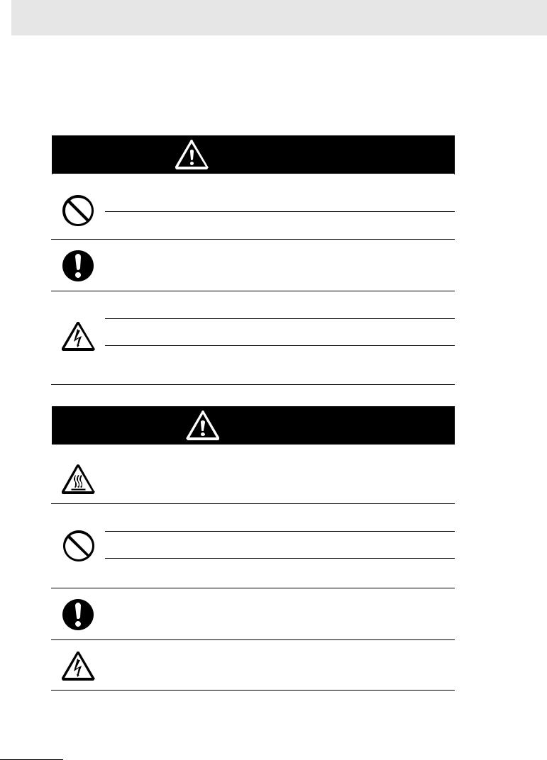
Meanings of Signal Words
Indicates a potentially hazardous situation which, if not
WARNING avoided, will result in minor or moderate injury, or may result in serious injury or death. Additionally there may be
significant property damage.
CAUTION |
Indicates a potentially hazardous situation which, if not |
avoided, may result in minor or moderate injury, or in |
|
property damage. |
Meanings of Alert Symbols
Example of symbols
General
Used for general CAUTION, WARNING, or DANGER precautions for which there is no specified symbol.
High temperature precaution
Used to warn of the risk of minor injury caused by high temperatures.
General
Used for general prohibitions for which there is no specific symbol.
General
Used for general mandatory action precautions for which there is no specified symbol.
Electric shock precaution
Used to warn of the risk of electric shock under specific conditions.
Always ground
Used to instruct the user to always connect the ground wire when using a device equipped with a safety ground terminal.
Grid Connect Photovoltaic Inverte KP100L-OD-USER’S MANUAL |
5 |
Alert Symbols in This Document
Important user information:
Observe the following warnings and cautions when using the KP100L.
WARNING
Significant property damage may possibly occur. Do not use the product in other country than the designated country.
Functional lesion by injury and fire damage may possibly occur. Do not remove the
MC cap on the back of the product when you exchange the FAN Assembly.
Ask to the store where you purchased the product or to an authorized service person when disposing of the product.
Injury by electric shock may possibly occur. Read this manual before installation, operating and maintenance of the product, and follow the instructions carefully.
Injury by electric shock may possibly occur. Do not open the cover foreside R during energizing.
Significant injury by electric shock may possibly occur. Do not touch the terminal of the MC connector. Do not remove the MC connector excluding the instruction of this manual.
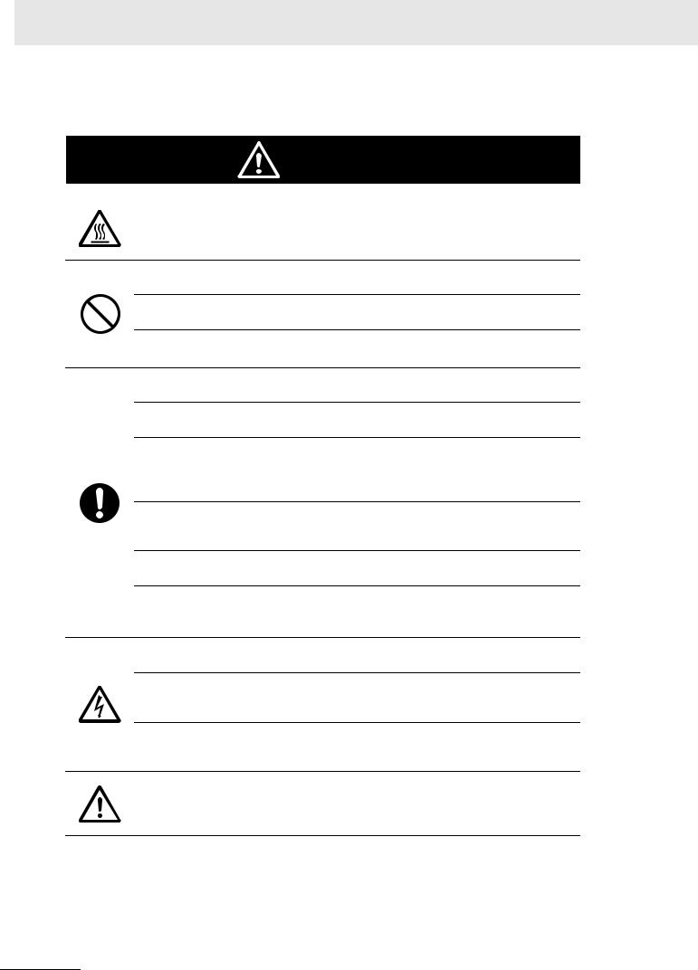
CAUTION
Burn injury may occasionally occur. Do not touch the upper part of the product while operating or immediately after having turned off power.
Fire damage or functional lesion of internal part may occasionally occur. Do not obstruct the heat sink or place any objects within 200mm of the heat sink.
Fire damage and malfunction may occasionally occur. Do not use the product that dropped or applied a strong impact.
Functional lesion by fire damage may occasionally occur. Do not unfasten of the MC connector and the cable clamp during operating.
The limitation of the output electric power by the ventilation trouble may occasionally occur. Clean the top and bottom of the heat sink regularly.
Injury or fire by electric shock may possibly occur. Do not open, disassemble, modify, or repair the cover front and the cover foreside L during operating.
6 |
Grid Connect Photovoltaic Inverte KP100L-OD-USER’S MANUAL |

Important installer information:
Observe the following warnings and cautions when installing the KP100L..
WARNING
Significant property damage may possibly occur. Do not use the product in other country than the designated country.
Significant property damage may possibly occur. Do not use the product with a mistake of the country setting.
Functional lesion by injury and fire damage may possibly occur. Do not remove the
MC cap on the back of the product when you exchange the FAN Assembly.
Significant property damage may possibly occur. Execute the installation by a person who has the qualification that authorized by the electric power company in the region.
Electric shock and significant property damage may possibly occur. Do a correct connection after confirming the polarity of the cable from the solar modules and from the grid.
Fire by loose connection of AC terminal block may possibly occur. Confirm there is no looseness in the screw of the AC terminal block during the maintenance.
When using the product by the state that tightening the screw of AC terminal block is insufficient, fire by loose connection may possibly occur.
Insert the electric cable in the inner of AC terminal block by using special Rod terminal and crimping pliers, and tighten the screw by tightening torque of
1.2-1.5N•m.
Fire by loose connection of the MC connector may possibly occur. Use the specialized tool for the crimping process of the MC connector. Insert the MC connector surely until locking.
Injury by electric shock may possibly occur. Read this manual before installation, operating and maintenance of the product, and follow the instructions carefully.
Injury or functional lesion by electric shock or burn injury may possibly occur. Do not install the product in places that child's hand reaches.
Injury by electric shock may possibly occur. Do not open the cover foreside R during energizing.
Significant injury by electric shock may possibly occur. Do not touch the terminal of the MC connector. Do not remove the MC connector excluding the instruction of this manual.
Significant injury by electric shock may possibly occur. Do not open the cover foreside R and not touch the MC connector for three minutes after turning OFF the breaker of the grid side and the solar module side.
Injury by electric shock may possibly occur. Connect the PE cable to the earth.
Grid Connect Photovoltaic Inverte KP100L-OD-USER’S MANUAL |
7 |
CAUTION
Burn injury may occasionally occur. Do not touch the upper part of the product while operating or immediately after having turned off power.
Fire damage or functional lesion of internal part may occasionally occur. Do not obstruct the heat sink or place any objects within 200mm of the heat sink.
Fire damage and malfunction may occasionally occur. Do not use the product that dropped or applied a strong impact.
Breakdown of DC input plug may occasionally occur. Do not put the product on ground with it had the DC input plug side below.
Injury may occasionally occur. Transport and place the product carefully by two persons or more.
Functional lesion by the fall of the product may occasionally occur. Use the installation parts and materials that are included in the product.
Functional lesion by fire damage of terminal may occasionally occur. Detach the MC connector by the state that turns off the breaker of the solar modules side. In the state that the current flows, inserting and removing of the MC connector is not allowed.
Break down or deterioration of the solar modules may occasionally occur. Install the breaker between the transformer and the KP100L when you connect the transformer. Connect the Neutral of the transformer to the earth.
Breakdown of internal part by static electricity may occasionally occur. Execute wiring after discharging static electricity.
Functional lesion by fire damage may occasionally occur. Confirm there is no looseness of the AC cable clamp, the communication cable clamp and the AUX cable clamp. Confirm the MC connector is locked.
Injury or fire by electric shock may possibly occur. Do not open, disassemble, modify, or repair the cover front and the cover foreside L during operating
Human hazard by electric shock or property damage by fire damage may occasionally occur. Mount the enclosed MC caps onto MC connector that is not used.
Electric shock or fire by the foreign body going into the product may occasionally occur. Prevent the foreign body from invading from the cover foreside R when wiring.
Functional lesion by injury and fire damage by the fall of the product may occasionally occur. Install the product in the location where the weight (41.5kg) of the product can be endured (the power of 176N•m torque per one screw can be endured).
8 |
Grid Connect Photovoltaic Inverte KP100L-OD-USER’S MANUAL |

Precautions for Safe Use
To use the product safely, what is executed or should evaded is shown.
Installation
Put the space of 200mm or more between the following.
•Between the product and the ceiling or eave
•Between the product and the floor
•Between the product and right and left wall
When you install the multiple KP100L, put the space of 200mm or more on the side of each KP100L. Do not install the multiple KP100L vertically.
Do not install in the location where the product receives direct sunlight or rain when you install in outdoor.
Do not install the product in the home or near the place where the person work because the audible noise generates when the product is oparating.
Transporting
Provide sufficient safety measures, such as scaffolding, to prevent danger during installation work.
Installation and Wiring
Make sure the following points when you install the product.
(1)Use the accessories included with KP100L.
(2)Make sure there is neither danger nor malfunction by the peripheral and the wire, etc. other than the accessory.
•When wiring to the AC terminal block, do not insert two or more wires into one terminal.
•Use the wire of the diameter that corresponds to the capacity of the Solar modules. Fire or smoke from fire may occur.
•IP65 performance can not be provided, if you don't follow these instructions:
(3)Use the cable of 18.5-20.5mm when you use the rubber bush of one hole for the AC cable clamp.
(4)Use the five cables of 3.5-4.0mm when you use the rubber bush of five holes for the AC cable clamp.
(5)Use the cable of 4mm for the communications cable and the AUX cable.
(6)Tighten the cable clamp.
(7)Tighten the screws of the cover foreside R by tightening torque 1.5-1.7 N m.
(8)Make sure the wire doesn't come off the terminal block after wiring the communication wire and the AUX wire to the terminal block.
Exchanging Fans (FAN Assembly)
Make sure the following precautions when exchanging FAN Assembly.
(1)Exchange the FAN Assembly after turning off the breaker of the grid side and the Solar module side and 3 minute or more pass. Electric shock and injury may occur.
(2)Use the specified FAN Assembly.
(3)Make sure the mounting direction of the FAN Assembly
(4)Tighten the screw correctly by tightening torque 1.5-1.7N m after exchanging FAN Assembly.
(5)Connect each connector of the FAN Assembly to the product correctly.
Grid Connect Photovoltaic Inverte KP100L-OD-USER’S MANUAL |
9 |
Solar Module
• Do not connect the solar module that has an open-circuit voltage in excess of 850 VDC.
• Do not connect the solar module that require earthing of negative or positive pole.
Breaker
• Use the breaker that corresponds to the capacity of the solar modules for the breaker of the Solar modules side.
• Use the 20A trip breaker with B or C or D trip characteristics for the breaker of the grid side.
Maintenance - Inspection
•Be sure to inspect install condition, wiring connection, before doing a trial operation.
•To secure the IP65 performance, execute the additional tightening of the cable clamp regularly.
10 |
Grid Connect Photovoltaic Inverte KP100L-OD-USER’S MANUAL |

Precautions for Correct Use
To prevent the adverse effect on the operation, what is executed or should be evaded is shown below.
Installation
•Install the product in a regulated direction.
•Do not install the product in the following places.
(1)Locations subject to intense temperature change.
(2)Locations subject to volatile, flammable, corrosive, or other toxic gas.
(3)Locations subject to vibration and large shocks.
(4)Locations subject to water vapor, oil vapor, or condensation.
(5)Locations where the product may be immersed in water.
(6)Locations subject to electric fields, direct sunlight, poor ventilation
(ex. Narrow places where the ventilation would be obstructed or the ambient temperature conditions would be exceeded.).
(7)Locations subject to temperature and humidity conditions outside of the following ranges
•Temperature: 20 to 60 C
•Humidity: 4 to 100%RH (Without condensation or freezing)
(8)Locations more than 2,000 m above sea level.
(9)Locations subject to saltwater spray, such as on oceangoing vessels or near a seacoast.
(10)Locations subject to falling snow, accumulated snow, or wind-blown snow.
Protect the product by building a protective roof when you install the product in the snowy region.
(11)Locations near highly combustible something or heat sources (stoves, heaters, boilers, etc.
(12)Locations subject to being damaged the wiring by animals or other factors. Protect the wiring by, for example, placing wiring ducts.
(13)Locations subject to near the equipment (such as a radio or TV) that is likely to be affected by electric waves, or to near an antenna.
Use the Product
•Do not stand on the product or place any objects on the product.
•Serious human hazard by fire may possibly occur.
•Do not use the product in a flammable gas atmosphere (including flammable sprays such as pesticides).
•Electric shock or fire may occur. Ask an authorized service person or a qualified person with knowledge of electrical system when you install, add on, move or reinstall the product.
Grid Connect Photovoltaic Inverte KP100L-OD-USER’S MANUAL |
11 |

Surge protection
•Install the surge measures circuit corresponding to the output voltage
•and input voltage to protect the inverter from the lightning surge.
•To do a steady operation, install and use the product in places where the following situations are avoided.
(1)Locations where surge voltage of the grid is generated by influence of neighborhood facilities and equipment.
(2)Locations where the grid is unstable caused by influence of neighborhood facilities and equipment.
(3)In factory or the vicinity where the grid is unstable.
(4)Locations subject to noise that ungrounded consumer electronics generate.
Maintenance o Inspection
• Confirm that there is no abnormality such as rust on outside of the product during the maintenance.
Storage
•Store in locations where the temperature is within the range of 25 to 60 C
•(with no condensation or icing), and the humidity is 95 % maximum.
•Store in locations that is no more than 2,000 m above sea level.
12 |
Grid Connect Photovoltaic Inverte KP100L-OD-USER’S MANUAL |

Warning Labels
Warning Labels and Warning Description
The Warning labels are located on the KP100L as shown in the follow illustration. Be sure to follow the instructions
Grid Connect Photovoltaic Inverte KP100L-OD-USER’S MANUAL |
13 |
Checking After Unpacking
Checking the Product
On delivery, be sure to check that the delivered product is the KP100L that you ordered.
Should you find any problems with the product, immediately contact your nearest local sales representative or OMRON Sales Office.
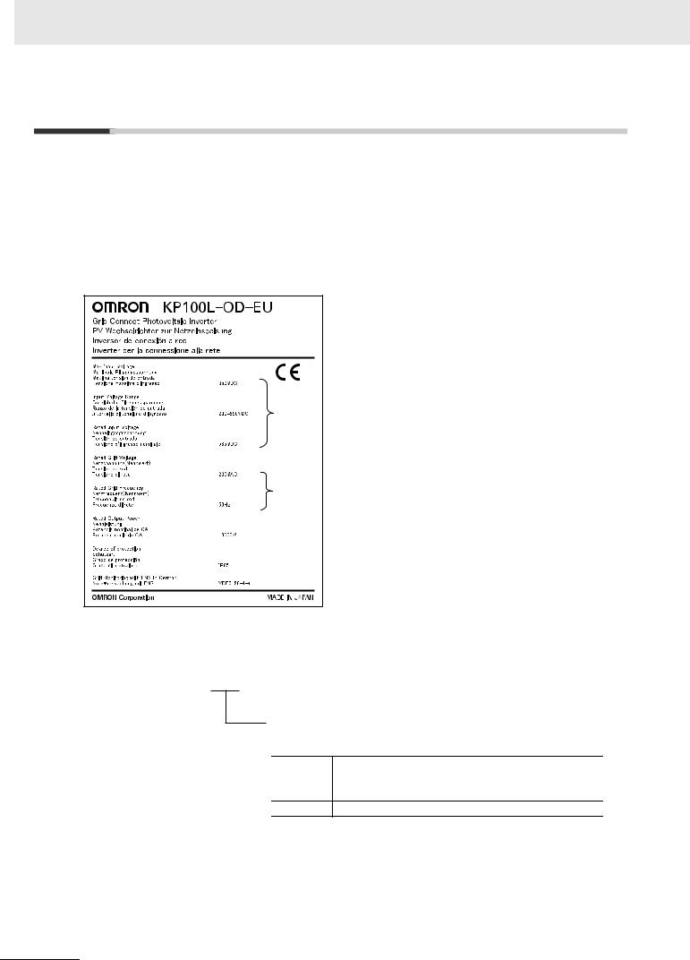
Checking the rating label
 Model
Model
 Specifications in DC
 Specifications in AC
Checking the Model
Type:KP100L-OD-
Correspondence country
Germany, Spain, Italy, France, Greece(Only mainland),
EU / EU-T Czech Republic, Denmark, Portugal, Turkey,
Republic of South Africa
KR Korea
14 |
Grid Connect Photovoltaic Inverte KP100L-OD-USER’S MANUAL |

Checking the Accessories
The follow items are included in the KP100L package. Check that all of the items shown in the package before you start the installation.
KP100L |
Mounting base plate QIG (Quick Install Guide) |
User’ s Manual |
|
Only KP100L-OD-EU/EU-T |
Only KP100L-OD-KR |
|
For KP100L-OD-EU/EU-T, PDF file is |
|
|
|
|
|
|
provided.Consult your OMRON representative |
|
|
to get PDF file |
The complete set of Accessories |
|
|
|
|
|
|
|
|
|
|
|
|
|
|
|
|
|
|
|
|
|
Items |
Number |
Note |
|
|
|
|
|
|
|
|
|
|
For installation of Mounting base plate |
|
|
|
|
|
|
|
|
Mounting Screw |
8 |
|
|
|
|
|
|
|
|
|
|
|
|
|
|
|
|
|
|
|
|
|
|
Tool of assistance when screw is stopped to hard wall |
|
|
|
|
|
|
|
|
Snap Bushing |
8 |
like concrete. |
|
|
|
|
|
|
|
|
|
|
|
|
|
|
|
|
|
|
|
M4 x 12mm Screw with |
|
For fixation of product set up in Mounting base plate |
|
|
|
|
|
|
|
|
|
|
|
|
|
|
|
|
|
||
plain washer and spring |
5 |
|
|
|
|
|
|
|
|
|
(4 peaces are for mounting, a peace is for reserve) |
|
|
|
|
|
|
|
|
||
washer |
|
|
|
|
|
|
|
|
|
|
|
|
|
|
|
|
|
|
|
|
|
M4 x 6mm Screw with plain |
2 |
Spare screw to fix the cover foreside R |
|
|
|
|
|
|
|
|
|
|
|
|
|
|
|
|
|||
|
|
|
|
|
|
|
|
|
||
|
|
|
|
|
|
|
|
|
||
washer and spring washer |
|
|
|
|
|
|
|
|
|
|
|
|
|
|
|
|
|
|
|
|
|
|
|
|
|
|
|
|
|
|
|
|
|
|
For connection of AC cable |
|
|
|
|
|
|
|
|
|
1 |
|
|
|
|
|
|
|
|
|
|
|
|
|
|
|
|
|
|
|
|
|
|
|
|
|
|
|
|
|
|
|
Rubber Bush |
1 |
For connection of AC cable |
|
|
|
|
|
|
|
|
|
|
|
|
|
|
|
|
|||
|
|
|
|
|
|
|
|
|
||
|
|
|
|
|
|
|
|
|
|
|
|
|
|
|
|
|
|
|
|
|
|
|
|
Spare rubber bush |
|
|
|
|
|
|
|
|
|
|
For connection of AUX and communication |
|
|
|
|
|
|
|
|
|
2 |
|
|
|
|
|
|
|
|
|
|
|
|
|
|
|
|
|
|
|
|
|
|
|
|
|
|
|
|
|
|
|
|
|
Caps for MC connection ( + ) |
|
|
|
|
|
|
|
|
|
2 |
These are attached to KP100L. |
|
|
|
|
|
|
|
|
|
|
|
|
|
|
|
|
|
|
|
MC Caps |
|
|
|
|
|
|
|
|
|
|
|
Caps for MC connection ( - ) |
|
|
|
|
|
|
|
|
|
|
|
|
|
|
|
|
|
|
|
|
|
2 |
These are attached to KP100L |
|
|
|
|
|
|
|
|
|
|
|
|
|
|
|
|
|
|
|
|
|
|
|
|
|
|
|
|
|
|
Safekeeping of the Original Carton Box
Keep the original carton box and use it when you transport the KP100L for repair service etc.
Grid Connect Photovoltaic Inverte KP100L-OD-USER’S MANUAL |
15 |

About This Manual
This Manual is compiled chapter by chapter for user's and installer's convenience as follows. You understand the follow configuration ensures more good operation of the product
|
|
Content / Exposition |
For Users |
For |
|
|
|
Installers |
|||
|
|
|
|
||
|
|
|
|
|
|
Chapter 1 |
Overview |
Describes features and names of parts. |
|
|
|
|
|
|
|
|
|
|
|
Provides external dimensions, installation |
|
|
|
Chapter 2 |
Design |
dimensions and other information necessary for |
|
||
|
|
design. |
|
|
|
|
|
|
|
|
|
|
|
Describes the name of parts of the operations |
|
|
|
Chapter 3 |
Operation |
and the monitor. Describes the monitor function |
|||
|
|
of the product. |
|
|
|
|
|
|
|
|
|
|
|
Describes the causes and their |
|
|
|
Chapter 4 |
Maintenance Operations |
countermeasures if the product fails, including |
|
|
|
the solutions to possible troubles |
|||||
|
|
|
|
||
|
|
(troubleshooting). |
|
|
|
|
|
|
|
|
|
Chapter 5 |
Inspection and |
Describes inspection and maintenance of the |
|
|
|
Maintenance |
product. |
||||
|
|
|
|||
|
|
|
|
|
|
Chapter 6 |
After-Sales Service |
Describes after-sales service and contact of the |
|
|
|
product. |
|||||
|
|
|
|
||
|
|
|
|
|
|
Chapter 7 |
Specifications |
Describes specifications of the product. |
|
|
|
|
|
|
|
|
|
Appendix |
|
Describes contents of the displays other than |
|
|
|
|
|||||
|
English. |
||||
|
|
|
|
||
|
|
|
|
|
|
|
|
|
|
|
16 |
Grid Connect Photovoltaic Inverte KP100L-OD-USER’S MANUAL |
|
|
|
|
|
|
Grid Connect Photovoltaic Inverte KP100L-OD-USER’S MANUAL |
17 |
|

Contents
|
|
Introduction............................................................................................................................... |
1 |
|
|
Read and Understand this Manual.......................................................................................... |
2 |
|
|
Safety Precautions ................................................................................................................... |
5 |
|
|
Precautions for Safe Use ......................................................................................................... |
9 |
|
|
Precautions for Correct Use................................................................................................... |
11 |
|
|
Warning Labels ....................................................................................................................... |
13 |
|
|
Checking After Unpacking..................................................................................................... |
14 |
|
|
About This Manual ................................................................................................................. |
16 |
Chapter 1 |
Overview ............................................................................ |
1-1 |
|
|
|
|
|
1-1 |
Model Name ........................................................................................................................... |
1-2 |
|
1-2 |
Functions ............................................................................................................................... |
1-3 |
|
|
1-3 Appearance and Names of Parts.......................................................................................... |
1-9 |
|
Chapter 2 |
Design ................................................................................ |
2-1 |
|
|
|
|
|
2-1 |
Typical System Configuration .............................................................................................. |
2-2 |
|
2-2 |
Application information ........................................................................................................ |
2-5 |
|
2-3 |
Installation............................................................................................................................. |
2-7 |
|
2-4 |
Wiring ................................................................................................................................... |
2-11 |
|
2-5 |
Check List ............................................................................................................................ |
2-24 |
|
|
2-6 Connecting to the Grid........................................................................................................ |
2-25 |
|
2-7 |
Maintenance Parts ............................................................................................................... |
2-27 |
|
2-8 |
Options ................................................................................................................................. |
2-28 |
|
Chapter 3 |
Operation ........................................................................... |
3-1 |
|
|
|
|
|
|
3-1 Part Names and Descriptions of Operation and Display Part ........................................... |
3-4 |
|
|
3-2 Procedure at the First Time Operation ................................................................................ |
3-5 |
|
3-3 |
Display transition .................................................................................................................. |
3-8 |
|
3-4 |
State Display .......................................................................................................................... |
3-9 |
|
3-5 |
Mode Selection Display ...................................................................................................... |
3-11 |
|
|
3-6 Setting in Particular Countries........................................................................................... |
3-20 |
|
|
3-7 Confirm method of LCD display......................................................................................... |
3-28 |
|
Chapter 4 |
Maintenance Operations .................................................. |
4-1 |
|
|
|
|
|
4-1 |
Outline of error ...................................................................................................................... |
4-2 |
|
4-2 |
Remedy for errors ................................................................................................................. |
4-3 |
|
4-3 |
Buzzer................................................................................................................................... |
4-10 |
|
4-4 |
Troubleshooting .................................................................................................................. |
4-11 |
|
18 |
Grid Connect Photovoltaic Inverte KP100L-OD-USER’S MANUAL |

Chapter 5 Inspection and Maintenance ............................................ |
5-1 |
||
|
|
|
|
5-1 |
Inspection and Maintenance ................................................................................................ |
5-2 |
|
5-2 |
Storage ................................................................................................................................... |
5-6 |
|
Chapter 6 |
After-Sales Service............................................................ |
6-1 |
|
|
|
|
|
6-1 |
After-Sales Service................................................................................................................ |
6-2 |
|
6-2 |
Contact ................................................................................................................................... |
6-3 |
|
Chapter 7 |
Specifications.................................................................... |
7-1 |
|
|
|
|
|
7-1 |
Standard Specification List .................................................................................................. |
7-2 |
|
Chapter A |
Appendix............................................................................ |
A-1 |
|
|
|
|
|
|
A-1 |
Error list.................................................................................................................................. |
A-2 |
|
A-2 |
LCD messages (Local Language) ........................................................................................ |
A-4 |
Grid Connect Photovoltaic Inverte KP100L-OD-USER’S MANUAL |
19 |
20 |
Grid Connect Photovoltaic Inverte KP100L-OD-USER’S MANUAL |

1
Overview
1-1 Model Name . . . . . . . . . . . . . . . . . . . . . . . . . . . . . . . . . . . . . . . . . . . . . . . . . . 1-2
1-2 Functions . . . . . . . . . . . . . . . . . . . . . . . . . . . . . . . . . . . . . . . . . . . . . . . . . . . . 1-3
1-3 Appearance and Names of Parts . . . . . . . . . . . . . . . . . . . . . . . . . . . . . . . . . 1-9
Grid Connect Photovoltaic Inverte KP100L-OD-USER’S MANUAL |
1 - 1 |

1 Overview
1-1 Model Name
Model |
Country |
|
KP100L-OD-EU / EU-T |
Germany, Spain, Italy, France, Greece(Only mainland),Czech Republic, |
|
Denmark, Portugal, Turkey, Republic of South Africa |
||
|
||
KP100L-OD-KR |
Korea |
1 - 2 |
Grid Connect Photovoltaic Inverte KP100L-OD-USER’S MANUAL |

1 Overview
1-2 Functions
System description
The KP100L converts DC power obtained from the solar modules into the AC power that is used in businesses, and enables interconnection with the grid.
This makes it possible to purchase power from the grid during periods when the load is high, and to sell power to the grid during periods when the load is low. (Please note that a contract must be concluded with the grid for this purchasing and selling transaction.) The system configuration of the KP100L is shown in the figure bellow.
Solar module |
DC |
switch |
or |
breaker |
SPD |
MPPT |
|
|
|
|
|
EMI |
|
|
|
|
Grid |
Filter |
|
|
|
|
|
Booster1 |
|
DC/AC |
|
|
|
MPPT |
|
|
|
|
|
DC Bus |
RLY1 RLY2 |
|
L1 |
AC breaker |
|
|
|
||||
EMI |
|
|
|
L2 |
Ground fault |
Filter |
|
|
EMI |
L3 |
breaker (RCD) |
Booster2 |
|
|
|||
|
|
|
N |
|
|
MPPT |
|
|
|
SPD |
|
|
|
|
PE |
|
|
EMI |
|
|
|
|
|
|
|
|
|
|
|
Filter |
|
|
|
|
|
Booster3 |
|
CPU1 CPU2 |
|
|
|
Communication |
|
AUX facility |
|
||
AUX_IN |
AUX_OUT |
|
|
||
facility |
|
|
|
||
RS-232C or RS-485 |
|
|
|
|
|
Functions 2-1
1
Grid Connect Photovoltaic Inverte KP100L-OD-USER’S MANUAL |
1 - 3 |

1 Overview
MPPT (Maximum Power Point Tracking)
3 pairs of positive and negative DC input channels are connected to three sets of MPP Tracking.
The output power of solar modules varies depending on the sunshine irradiation and the temperature of the modules. In order to use the unstable output of the solar modules efficiently, the KP100L searches for the operating voltage that will produce the maximum output power while it converts the DC input voltage. The KP100L has 3 MPPT. The topology of the MPPT is mainly a booster. Each booster steps up the DC input voltage to a higher DC BUS voltage. User can connect differently-aligned string as 3 MPPT operate independently as illustrated in the figure bellow. This construction achieves high power generation and flexible sizing of PV string.
DCP |
Solar module 1 |
+ |
|
||
|
DCV |
- |
DCP |
Solar module 2 |
+ |
|
DCV |
- |
|
|
|
DCP |
Solar module 3 |
+ |
|
DCV |
- |
|
|
Input specifications:
a)DC input voltage range: 200 to 850 VDC
b)MPPT voltage range: 225 to 800 VDC
Input limitations:
a)Maximum input open-circuit voltage: 850 VDC
b)Maximum input current per Tracking: 13 ADC MPPT controls not to exceed 13 ADC.
c)Maximum input power per Tracking: 5500 W MPPT controls not to exceed 5500 W.
DC Bus
The three sets of MPPT store DC power via the DC/DC booster to the DC bus.
DC/AC Inverter
The DC bus is connected to the DC/AC inverter, which converts DC power to AC power.
Grid-Connection Relays
The two relays, RLY1 and RLY2, control the connection of the KP100L to grid via CPU1 and CPU2.
Output Lines
4 output lines (L1, L2, L3 and N) and PE represent the 3-phase 4-wire AC power transmission to grid.
1 - 4 |
Grid Connect Photovoltaic Inverte KP100L-OD-USER’S MANUAL |

1 Overview
Communication Facility
RS-485 Communications
To communicate with multiple KP100L Units, you can connect them to a personal computer via RS-485 ports. The maximum cable length is 500 m.
RS-485 allows communication with up to 31 Units.
RS-485 communications require a cable of the appropriate length and a personal computer installed with monitoring software.
Baud rate is 4,800bps, 9,600bps or 19,200bps. Default value is 19,200bps. Available communication protocol is Compoway/F or MODBUS.
[example 1] up to 31 units
RS-232C/RS-485
Converter |
RS-485 |
[example 2] up to 31 units
Functions 2-1
1
RS-485
RS-232C
modem modem
Grid Connect Photovoltaic Inverte KP100L-OD-USER’S MANUAL |
1 - 5 |

1 Overview
[example 3] PLC(Programmable Logic Controller):up to 4 units KP100L:up to 124 units
PLC |
RS-485 |
PLC |
RS-485 |
|
PLC |
RS-485 |
|
PLC |
RS-485 |
|
RS-232C Communications
The simplest and least expensive way to communicate between a single KP100L and a personal computer is to connect directly via RS-232C ports. The maximum cable length between the personal computer and the KP100L is 15 m.
RS-232C
1 - 6 |
Grid Connect Photovoltaic Inverte KP100L-OD-USER’S MANUAL |
1 Overview
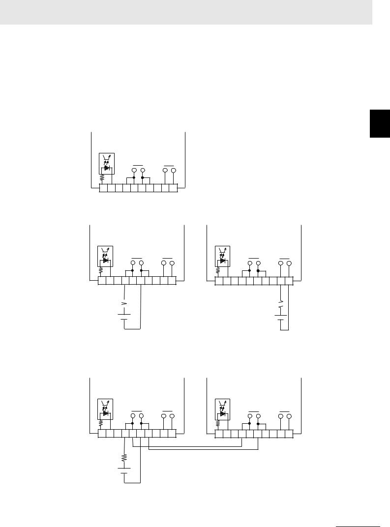
AUX Facility
Relay Output
The KP100L has the 2 relays for 2 output signals of the table below. Refer to"3-5 Parameter List" for the setting of the output signal. Refer to"2-4 Wiring " for connecting the AUX cable.
Name |
Type of contact |
Specifications |
AUX_OUT1 |
SPST-NO |
250 VAC / 1 A, 30 VDC / 1 A ( Resistive load) |
AUX_OUT2 |
SPST-NO |
Minimum permissive load 20mA |
KP100L
AUX_IN
AUX_OUT1 AUX_OUT2
1 |
2 |
3 4 |
5 |
6 |
7 |
8 |
9 10 |
AUX Terminal Block
[Example when you use AUX_OUT1 or AUX_OUT2]
KP100L
AUX_IN
AUX_OUT1 AUX_OUT2
1 |
2 |
3 4 |
5 |
6 |
7 |
8 |
9 10 |
AUX Terminal Block
(*)  510Ω
510Ω 
24VDC (*)
KP100L
AUX_IN
AUX_OUT1 AUX_OUT2
1 |
2 |
3 4 |
5 |
6 |
7 |
8 |
9 10 |
|
|
|
|
|
|
|
AUX Terminal Block |
510Ω
24VDC
(*)The external DC voltage and resistance value are example.
Select appropriate value according to your application.
[Example when you use AUX_OUT1 of multiple products]
KP100L
AUX_IN
AUX_OUT1 AUX_OUT2
1 |
2 |
3 4 |
5 |
6 |
7 |
8 |
9 10 |
AUX Terminal Block
KP100L
AUX_IN
AUX_OUT1 AUX_OUT2
1 |
2 |
3 4 |
5 |
6 |
7 |
8 |
9 10 |
AUX Terminal Block
Functions 2-1
1
Grid Connect Photovoltaic Inverte KP100L-OD-USER’S MANUAL |
1 - 7 |

1 Overview
Photo-Coupler Input
The KP100L has the photo-coupler for input signals of the table below. Refer to"3-5 Parameter List" for the setting of the input signal.
Name |
Type of contact |
Specifications |
|
|
10mA Use 24 VDC to use AUX_IN. |
|
|
Minimum ON time : 100ms |
AUX_IN |
Photo-Coupler |
Leakage current at OFF status 0.1mA |
|
|
Residual voltage at ON status 2.0V |
|
|
Capacity of external switch 20mA |
[Example when you use AUX_IN]
KP100L
AUX_IN
AUX_OUT1 AUX_OUT2
1 2 3 4 5 6 7 8 9 10
AUX Terminal Block
10mA
24VDC
1 - 8 |
Grid Connect Photovoltaic Inverte KP100L-OD-USER’S MANUAL |

1 Overview
1-3 Appearance and Names of Parts
Cover front
Cover foreside R
(for Wiring)
Heat sink
Cover foreside
Display 
Key
3-pairs of |
Fans |
|
DC Input plug |
AC Cable Clamp |
|
AUX Cable Clamp |
||
(MC4 connectors) |
||
Communication |
||
|
||
|
Cable Clamp |
(1) Fan
Fans
of Names and Appearance 3-1 Parts
1
Grid Connect Photovoltaic Inverte KP100L-OD-USER’S MANUAL |
1 - 9 |
 Loading...