


 Loading...
USER GUIDE
 INDUSTRIAL DATA COMMUNICATIONS
LCM100
Line Carrier Modem
It is essential that all instructions contained in the User Guide are followed precisely to ensure proper operation of equipment.

Product User Guide
FCC Information
Appropriate FCC info
DATA-LINC GROUP
PN 161-xxxxx-001A
 DATA-LINC GROUP
LCM100 User’s Guide
LCM100
Line Carrier Modem
Introduction
In the line carrier system, the hot line supplies current to connected loads and is also used as a carrier for data communication between modules. The Data-Linc LCM100 can communicate over the same line in a 240 volt single phase system or on any individual phase of a three-phase system.
Note: It will be necessary to have a signal coupler installed to ensure communications over different lines of the 240 volt, single phases system.
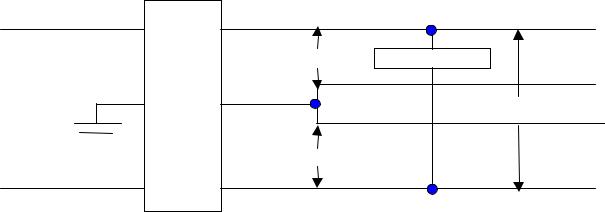
In the three-phase power environment, communication will occur freely if both devices are connected on the same phase, but cross-phase communication will require line conditioning by installation of a signal coupler between phases. As shown in Figure 1 below, two signal couplers are sufficient for all cross-plane combinations in a three-phase system. Installation of a signal coupler at the power distribution panel is fully described under the line conditioning section of this manual.
|
Hot |
|
|
|
120V |
signal coupler |
Load |
meter & |
|
|
|
circuit |
neutral |
|
220V |
breaker |
|
|
|
|
120V |
|
Load |
|
Hot |
|
|
Figure 1: Connecting a Signal Coupler, Single Phase System
The green wire is reference (earth) ground. It serves also as chassis ground and reduces equipment susceptibility to RF current, static discharge and interference from fluorescent lamps. The LCM100 system is designed to operate with a reference ground located at the power distribution panel. Reference ground is usually connected to the copy ground bus or to the distribution panel frame.
When the power cord is connected to a three-wire AC power outlet, the bottom round connector serves to ground the chassis, protecting against shock hazard, susceptibility to electro-magnetic interference and possible spurious emissions.
PN 161-09998-001A |
2 |
Loading...