


 Loading...
Cat. No. N102-E1-04
K3GN
1/32 DIN Digital Panel Meter
USER’S MANUAL

PREFACE
This User’s Manual provides you with information necessary for use of the K3GN series of digital panel meters.
Please read this manual carefully to ensure correct and efficient use of the product. Keep this manual handy for future reference.
General Precautions
If contemplating using the product in the following environments or for the following equipment, first contact a sales representative of the company and then accept responsibility for incorporating into the design fail-safe operation, redundancy, and other appropriate measures for ensuring reliability and safety of the equipment and the overall system.
(1)Environments deviating from those specified in this manual
(2)Nuclear power control systems, traffic (rail car/automobile/aircraft) control systems, medical equipment, amusement equipment, and rescue and security equipment
(3)Other equipment that demands high reliability, including those related to the safety of life and property
About the Contents of the Manual
(1)Any reproduction, full or in part, of the manual is prohibited without prior written permission from the company.
(2)Specifications in the manual may be subject to change without notice.
(3)Information in the manual has been carefully checked for accuracy. If finding any suspicious or erroneous descriptions in the manual, however, you are kindly requested to contact a branch office of the company. In such a case, please let us know the Cat. No. shown on the front cover of the manual.
I

Other Informations
1Warranty
(1)Warranty Period
The warranty period for an OMRON Product is one year from either the date of purchase or the date on which the OMRON Product is delivered to the specified location.
(2) Extent of Warranty
If an OMRON Product is subject to a failure for which OMRON is responsible during the warranty period, either a replacement product will be provided or the defective product will be repaired free of charge at the place of purchase, This warranty, however, will not cover problems that occur as a result of any of the following.
a)Using the OMRON Product under conditions or in an environment not described in catalogs or in the specifications, or not operating the OMRON Product according to the instructions contained in catalogs or in the specifications.
b)Problems caused by something other than the OMRON Product.
c)Modifications or repairs performed by a party other than OMRON.
d)Using the OMRON Product for other than its designed purpose.
e)Problems that could not have been foreseen with the level of science and technology that existed at the time the OMRON Product was shipped.
f)Problems caused by an Act of God or other circumstances for which OMRON is not responsible.
This warranty covers only the OMRON Product itself. It does not cover any other damages that may occur directly as a result of a problem with the OMRON Product.
2 Limitations of Liability
(1)OMRON shall not be responsible for special, indirect, or consequential damages originating in an OMRON Product.
(2)For programmable OMRON Products, OMRON does not accept responsibility for any programming that is performed by a party than OMRON, or for any results arising from that programming.
3 Applicable Conditions |
|
(1) When using OMRON Products in combination with other products, it is use’s |
responsibility to confirm |
the suitability of the OMRON Products for the system, devices, and equipment that are being used. OMRON accepts no responsibility for the suitability of OMRON Products used in combination with other products.
(2) When using OMRON Products in any of the following applications, consult an OMRON representative and check specifications to allow sufficient leeway in ratings and performance, and to implement suitable safety measures, such as safety circuits, to minimize danger in the event of an accident.
a)Outdoor applications, applications with potential for chemical contamination or electrical interference, or application under conditions or environments not described in catalogs.
b)Nuclear control systems, railroad systems, aviation systems, vehicles, combustion systems, medical equipment, amusement machines, or equipment regulated by government or Industrial standards.
c)Other systems, machines, and equipment that may have a serious influence on human life and property.
d)Equipment requiring a high level of reliability, such as gas, water, or electrical supply systems, and systems that operate 24 hours a day.
e)Other applications requiring a high level of safety, corresponding to points a) to d), above.
(3)When OMRON Products are used in an application that could pose significant risk to human life or property, the overall system must be designed so that the required safety can be ensured by providing notice of the danger and incorporating redundancy into the design. Make sure that OMRON Products are appropriately wired and mounted to serve their intended purpose in the overall system.
(4)Application examples provided in catalogs are for reference only. Confirm functionality and safety before actually using the devices and equipment.
(5)To prevent unexpected problems from arising due to the OMRON Product being used incorrectly by the customer or any other party, make sure that you understand and carefully observe all of the relevant prohibitions and precautions.
4 Changes to Specifications
Specifications and accessories to the products in catalogs may be changed as needed to improve the products or for any other reason. Check with your OMRON representative for the actual specifications for OMRON Products at the time of purchase.
5 Applicability
The above information assumes that business and product application will be conducted in Japan. For business and application outside of Japan, consult with your OMRON representative.
II
Signal Words and Safety Notices
Signal Words
In this manual, safety notices are divided into WARNING and CAUTION according to the hazard level.
As both of WARNING and CAUTION notices contain important information for ensuring safety, be sure to observe them.
A signal word indicating a potentially hazardous CAUTION situation which, if not avoided, may result in minor or
moderate injury or property damage.
Symbols
Indicates a CAUTION or WARNING with the specific contents indicated in the triangle and described in text. The example at the left is for a general precaution.
Indicates a prohibition with the specific contents described in text, which is general unless otherwise classified.
Indicates a prohibition with the specific contents indicated behind the circle and slash and described in text. The example at the left is for prohibiting disassembling.
Indicates a mandatory action with the specific contents indicated in the circle and described in text. The example at the left is for a general mandatory action that is not classified otherwise.
III
Safety Notices
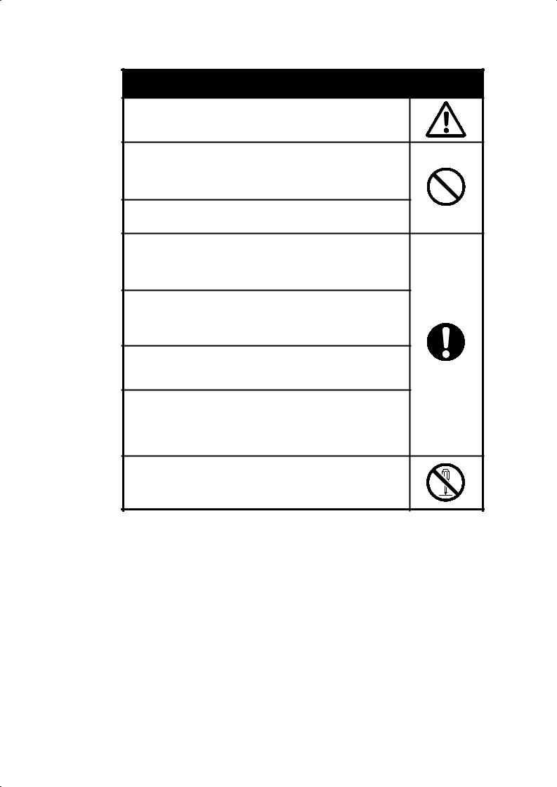
 CAUTION
Do not touch the terminals while power is being supplied.
Doing so may possibly result in electric shock
Do not allow pieces of metal, wire clippings, or fine metallic shavings or filings to enter the product.
Doing so may occasionally result in minor or moderate injury or in property damage due to electric shock, fire, or malfunction caused by internal short circulation..
Do not use the product in locations where flammable or explosive gases are present. Doing so may occasionally result in minor or moderate explosion, causing minor or moderate injury, or property damage.
Do not use the equipment for measurements within Measurement Categories or (according to IEC61010-1). Doing so may occasionally cause unexpected operation, resulting in minor or moderate injury, or damage to the equipment. Use the equipment for measurements only within the Measurement Category for which the product is designed.
Failure to perform correct setting of the product according to the application may occasionally cause unexpected operation, resulting in minor or moderate injury, or damage to the equipment.
Ensure safety in the event of product failure by taking safety measures, such as installing a separate monitoring system.
Ensure safety in the event of product failure by taking safety measures, such as installing a separate monitoring system.
Product failure may occasionally prevent operation of comparative outputs, resulting in damage to the connected facilities and equipment.
Tighten the screws on the terminal block and the connector locking screws securely using a tightening torque within the following ranges. Loose screws may occasionally cause fire, resulting in minor or moderate injury, or damage to the equipment.
Terminal block screws : 0.43 to 0.58 N·m. Connector locking screws :
Do not attempt to disassemble, repair, or modify the product. Doing so may occasionally result in minor or moderate injury due to electric shock.
IV

Precautions for Safe Use
Precautions for the environment.
(1)Do not use the product in the following locations.
•Locations subject to direct radiant heat from heating equipment
•Locations here the product may come into contact with water or oil
•Locations subject to direct sunlight
•Locations where dust or corrosive gases (in particular, sulfuric or ammonia gas) are present
•Locations subject to extreme temperature changes
•Locations where icing or condensation may occur
•Locations subject to excessive shocks or vibration
(2)Do not use the product in locations subject to temperatures or humidity levels outside the specified ranges or in locations prone to condensation. If the product is installed in a panel, ensure that the temperature around the product (not the temperature around the panel) does not go outside the specified range. Parts life is dependent on temperatures. A part life shortens when the temperature rises, and it lengthens when the temperature falls. Parts life can be lengthened by lowering the temperature inside the product.
(3)In order to prevent inductive noise, wire the lines connected to the product separately from power lines carrying high voltages or currents. Do not wire in parallel with or in the same cable as power lines. Other measures for reducing noise include running lines along separate ducts and using shield lines.
(4)Do not install the product near devices generating strong high-frequency waves or surges. When using a noise filter, check the voltage and current and install it as close to the product as possible. If several products are mounted side-by-side or arranged in a vertical line, the heat dissipation will cause the internal temperature of the product to rise, shortening the service life. If necessary, cool the products using a fan or other cooling method.
(5)Take care when cleaning the product, because the exterior of the product contains organic solvent (thinner, benzine, etc.), strong alkaline material and strong acid material.
(6)Avoid storing in high humidity or in a corrosive gas environment (including during transportation)
Precautions for Safe Use.
(1)Use and store within the proper temperature and humidity described in the specifications.
(2)Provide sufficient space around the product for heat dissipation.
(3)When using the product stored unused over a year after purchasing, the product features may not be utilized sufficiently.
(4)Avoid storing outdoors and in a place that receives direct sunlight (including during transportation).
(5)The service life of the output relays depends on the switching capacity and switching conditions. Consider the actual application conditions and use the product within the rated load and electrical service life. Using the product beyond its service life may result in contact welding or burning.
(6)Be sure to confirm the name and polarity for each terminal before wiring the terminal block and connectors. Faulty wiring causes destruction or burnout of internal parts.
(7)Use the product within the noted supply voltage and rated load.
(8)Do not connect anything to unused terminals.
(9)Output turns OFF when the mode is changed or settings are initialized. Take this into consideration when setting up the control system.
V

(10)Install an external switch or circuit breaker and label them clearly so that the operator can quickly turn OFF the power.
(11)Ensure that the rated voltage is achieved no longer than 2 s after turning the power ON. When applying a voltage gradually, power supply may not be reset or output functions indeterminately.
(12)Mount to a panel between 1 and 5 mm thick.
(13)Use the specified size of crimp terminals (M3, width : 5.8 mm max.) for wiring. To connect bare wires, use AWG 28 to AWG 16 to wire the power supply terminals and AWG 22 to AWG 14 for other terminals. (Length of exposed wire : 6 to 8 mm)
(14)Allow the product to operate without load for at least 15 minutes after the power is turned ON.
VI
Precautions for Correct Use
(1)Install the product horizontally. Display error has the risk of becoming larger than the standard because heat cannot be radiated.
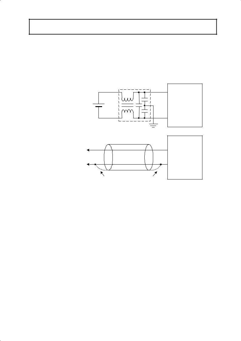
(2)When using a noise filter on the power supply, check that the filter is suitable for the supply voltage and current ratings, and then attach the noise filter as close as possible to the K3GN.
<Examples of noise prevention schemes>
|
Line filter |
|
24VDC |
Power |
Digital Panel |
|
supply |
|
|
Meter |
|
|
input |
|
|
|
Shielded cable
Signal |
Digital Panel |
input |
Meter |
Connect in the direction that best reduces noise.
(3) If placed near the product, radios, TVs, or other wireless devices may suffer reception interference..
VII

Alphabetic Characters for Setting Data
This manual uses the following alphabetic characters for setting data.
a |
|
b |
c |
d |
e |
f |
g |
h |
i |
j |
k |
l |
m |
|
|
|
|
|
|
|
|
|
|
|
|
|
|
A |
|
B |
C |
D |
E |
F |
G |
H |
I |
J |
K |
L |
M |
|
|
|
|
|
|
|
|
|
|
|
|
|
|
|
|
|
|
|
|
|
|
|
|
||||
n |
o |
p |
q |
r |
s |
t |
u |
v |
w |
x |
y |
z |
|
|
|
|
|
|
|
|
|
|
|
|
|
|
|
N |
O |
P |
Q |
R |
S |
T |
U |
V |
W |
X |
Y |
Z |
|
|
|
|
|
|
|
|
|
|
|
|
|
|
|
VIII

Table of Contents
|
|
|
................................................................................................................PREFACE |
I |
|
|
|
General Precautions.................................................................................................. |
I |
|
|
|
Other Informations ................................................................................................. |
II |
|
|
|
Signal Words and Safety Notices .......................................................................... |
|
|
|
|
Safety Precautions ................................................................................................. |
IV |
|
|
|
Installation and Noise Prevention Tips................................................................... |
V |
|
|
|
.................................................................Alphabetic Characters for Setting Data |
VI |
CHAPTER 1 |
INTRODUCTION ............................................................. |
1 |
||
|
1.1 |
Main Features.......................................................................................................... |
2 |
|
|
1.2 |
Model Number Legend............................................................................................ |
4 |
|
|
1.3 |
I/O Circuits.............................................................................................................. |
5 |
|
|
1.4 |
Parts Name and Function......................................................................................... |
8 |
|
CHAPTER 2 |
INSTALLATION AND CONNECTION .............................. |
9 |
||
|
2.1 |
Installation............................................................................................................. |
10 |
|
|
2.2 |
I/O Terminal Connections ..................................................................................... |
12 |
|
CHAPTER 3 |
APPLICATION EXAMPLES........................................... |
15 |
||
|
3.1 |
Monitoring the Remaining Quantity of Soup ........................................................ |
16 |
|
|
3.2 |
Monitoring the Load Current of a Motor............................................................... |
18 |
|
|
3.3 |
Monitoring the Quantity of Dust ........................................................................... |
20 |
|
|
3.4 |
Monitoring the Internal Pressure of a Tank........................................................... |
22 |
|
|
3.5 |
Monitoring the Rotational Speed of a Motor......................................................... |
24 |
|
|
3.6 |
Using the Product as a Digital Indicator for PLC.................................................. |
26 |
|
CHAPTER 4 |
INITIAL SETTING.......................................................... |
29 |
||
|
4.1 |
Using the Product as a process meter .................................................................... |
30 |
|
|
4.2 |
Using the Product as a Tachometer ....................................................................... |
32 |
|
|
4.3 |
Using the Product as a Digital Indicator for PLC Data ......................................... |
34 |
|
CHAPTER 5 |
OPERATION.................................................................. |
37 |
||
|
5.1 |
Levels .................................................................................................................... |
38 |
|
|
5.2 |
Moving among Levels........................................................................................... |
39 |
|
|
5.3 |
Parameters ............................................................................................................. |
42 |
|
|
5.4 |
Set Values.............................................................................................................. |
44 |
|
|
5.5 |
Operation Level..................................................................................................... |
45 |
|
|
5.6 |
Communication Writing Control........................................................................... |
47 |
|
IX
|
5.7 |
Key Protect Setting ................................................................................................ |
48 |
|
5.8 |
Selecting an Input Type ......................................................................................... |
50 |
|
5.9 |
Selecting an Analog Range.................................................................................... |
51 |
|
5.10 |
Selecting an Input-pulse Frequency Range............................................................ |
52 |
|
5.11 |
Specifying the Scaling Factor for Analog Input/Digital Data Display................... |
53 |
|
5.12 |
Specifying the Scaling Factor for Input Pulse Frequency...................................... |
55 |
|
5.13 |
Specifying the Decimal Point Position .................................................................. |
58 |
|
5.14 |
Selecting the Output Operating Action .................................................................. |
59 |
|
5.15 |
Performing Linear Output...................................................................................... |
60 |
|
5.16 |
Specifying Communication Parameters................................................................. |
63 |
|
5.17 |
Clearing All Parameters......................................................................................... |
65 |
|
5.18 |
Specifying the Number of Measurements for Averaging ...................................... |
66 |
|
5.19 |
Specifying the Function of the Event Input ........................................................... |
67 |
|
5.20 |
Specifying the Hysteresis....................................................................................... |
69 |
|
5.21 |
Specifying the Auto-zero Time.............................................................................. |
71 |
|
5.22 |
Specifying the Startup Compensation Time .......................................................... |
73 |
|
5.23 |
Changing the Display Color................................................................................... |
75 |
|
5.24 |
Changing the Display Auto-return Time................................................................ |
77 |
|
5.25 |
Changing the Move-to-Protect-Level Time ........................................................... |
79 |
|
5.26 |
Changing the Send Waiting Time.......................................................................... |
81 |
CHAPTER 6 |
FUNCTION DESCRIPTION .......................................... |
83 |
|
|
6.1 |
Measurement.......................................................................................................... |
84 |
|
6.2 |
Scaling ................................................................................................................... |
86 |
|
6.3 |
Auto-zero/Startup Compensation........................................................................... |
88 |
|
6.4 |
Average Processing................................................................................................ |
89 |
|
6.5 |
Event Input/Pulse Input.......................................................................................... |
90 |
|
6.6 |
Process Value Hold................................................................................................ |
91 |
|
6.7 |
Forced-zero ............................................................................................................ |
92 |
|
6.8 |
Comparative Output............................................................................................... |
93 |
|
6.9 |
Hysteresis............................................................................................................... |
94 |
|
6.10 |
Display Color Change............................................................................................ |
95 |
CHAPTER 7 |
COMMUNICATIONS ..................................................... |
97 |
|
|
7.1 |
Communication Protocols...................................................................................... |
98 |
|
7.2 |
Data Format Structure............................................................................................ |
99 |
|
7.3 |
Structure of Command/Response Text ................................................................ |
101 |
|
7.4 |
Variable Area....................................................................................................... |
102 |
|
7.5 |
Read from Variable Area ................................................................................... |
103 |
|
7.6 |
Write to Variable Area ....................................................................................... |
104 |
|
7.7 |
Operation Instructions.......................................................................................... |
105 |
|
7.8 |
Setting Areas........................................................................................................ |
106 |
|
7.9 |
Commands and Responses................................................................................... |
107 |
|
7.10 |
Variable Area Map............................................................................................... |
115 |
|
7.11 |
Communications Control Flow............................................................................ |
118 |
|
7.12 |
Programming Example ........................................................................................ |
123 |
X

CHAPTER 8 |
USER CALIBRATION.................................................. |
127 |
|
|
8.1 |
User Calibration .................................................................................................. |
128 |
|
8.2 |
User Calibration Processes .................................................................................. |
130 |
CHAPTER 9 |
TROUBLESHOOTING GUIDE .................................... |
133 |
|
|
9.1 |
Error Indications.................................................................................................. |
134 |
|
9.2 |
Troubleshooting Table......................................................................................... |
135 |
|
APPENDIX ................................................................... |
137 |
|
|
|
Specifications ............................................................................................ |
138 |
|
|
Parameter List............................................................................................ |
142 |
|
|
ASCII Code Table...................................................................................... |
143 |
XI

1.1 Main Features
CHAPTER
1 INTRODUCTION
This chapter provides an overview of the product.
1.1Main Features 2
1.2Model Number Legend 4
1.3I/O Circuits 5
Input Circuit Diagrams/Output Circuit Diagrams/ Internal Block Diagram
1.4 Parts Name and Function 8
1
INTRODUCTION
INTRODUCTION
CHAPTER 1 INTRODUCTION
1.1 Main Features
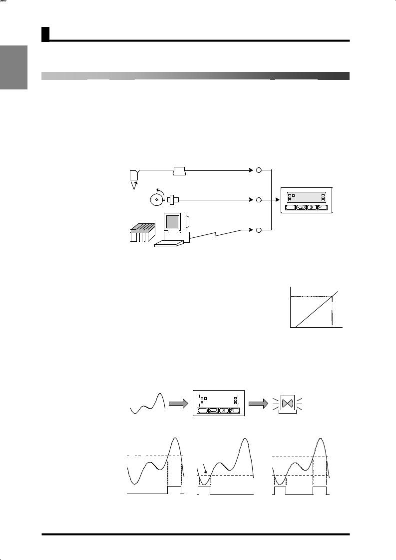
The K3GN is a digital panel meter that is capable of converting an input signal into a digital value and displaying it on the main indicator.
The main futures of the product include the following.
Measurement |
This feature measures an input signal and displays it as a digital value. |
|
An analog value (voltage/current), a rotational speed (pulses), or digital data |
|
received via communication function can be selected as an input signal. |
Voltage/current
|
|
K3GN |
|
|
ON/OFF |
OUT1 |
T |
((((8 |
ZERO |
OUT2 |
8 |
HOLD |
||
|
SV |
|
|
CMW |
/ZERO |
RS485
PLC
PC
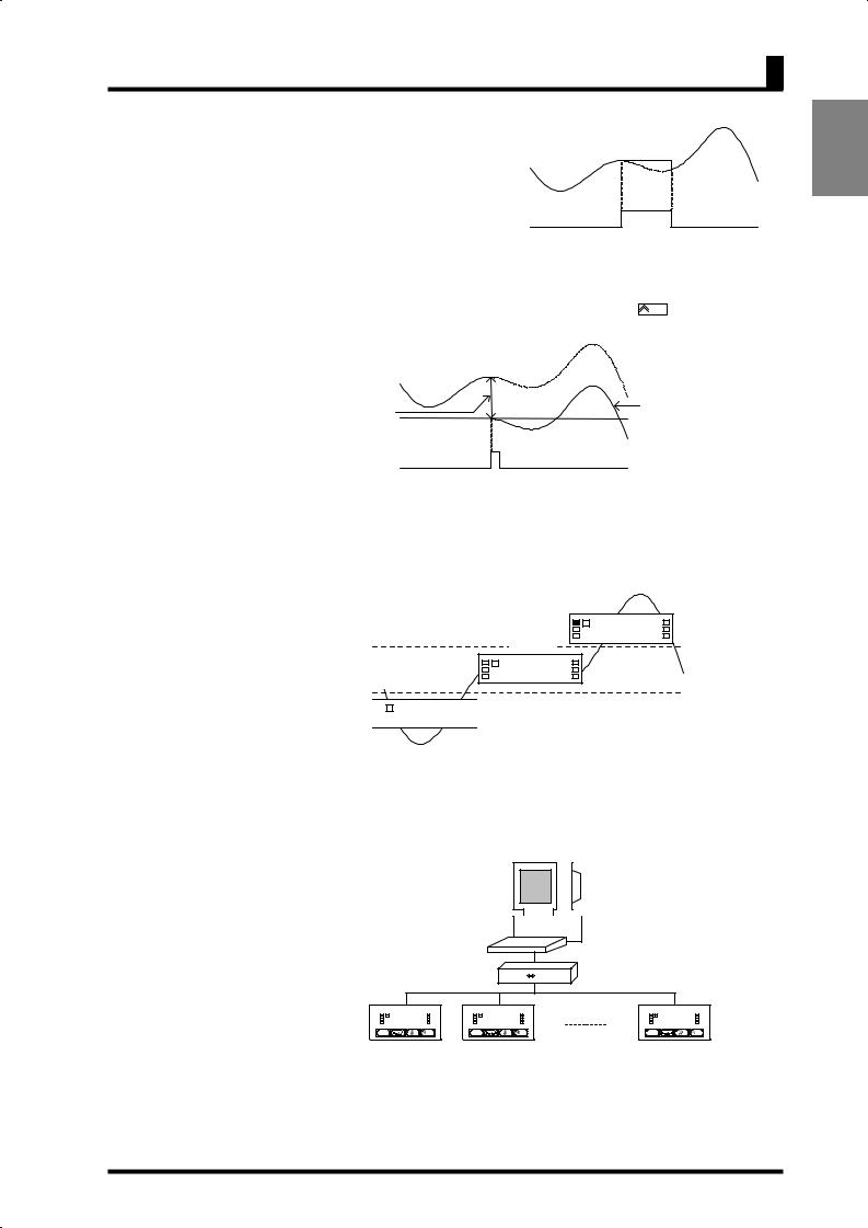
Scaling This feature converts an input signal into a desired physical value
The figure on the right shows a scaling example where input signals from a pressure sensor ranging from 4 to 20 mA are converted into values ranging from 0 to 100 (kPa). Scaling will enable you to handle physical quantities easily and intuitively.
Readout |
|
|
100kPa |
|
|
0kPa |
Input |
|
20mA |
||
4mA |
|
|
|
Comparative |
This feature compares a scaled (process) value with a programmed OUT set value |
|
Output |
|
and produces output according to the comparison result. |
|
|
This is useful in monitoring various systems for malfunction or determining |
|
|
|
|
|
whether products are within acceptance limits. |
 K3GN
K3GN
|
|
|
|
|
|
OUT1 |
|
T |
((((8 |
|
ZERO |
OUT2 |
|
8 |
|
HOLD |
|
|
|
||||
SV |
|
|
|
|
CMW |
|
|
|
|
|
|
/ZERO |
Three types of comparative outputs are available: those produced at the OUT upper-limit value, the OUT lower-limit value, and both the OUT values.
OUT upper |
|
OUT upper |
limit value |
OUT lower |
limit value |
|
|
|
|
limit value |
|
|
|
OUT |
|
|
lower |
|
|
limit |
|
|
value |
Comparative output |
Comparative output |
Comparative output |
Comparative output |
Comparative output |
Comparative output produced at |
produced at the OUT upper |
produced at the OUT lower |
the OUT upper and lower limit |
limit value |
limit value |
values |
2
1.1 Main Features
Process |
This feature enables a process value |
Process |
|
Value Hold |
to be held while the external event |
||
value |
|||
|
input stays ON. |
|
|
|
The outputs are also retained. |
|
|
|
|
HOLD input |
|
Forced-zero |
This feature shifts a process value to zero, and can be used to evaluate and display |
||
|
the deviation of a process value from a reference value. |
||
|
The forced-zero function can be activated by using the /ZERO key on the front |
||
|
panel, via the event input terminal, or communications. |
||
|
Process |
|
value |
Forced-zero value |
Measurement value |
(shifted value) |
after executing the |
|
forced-zero function |
|
ZERO input |
Display Color
Change
Communi-cation
This feature allows programming of the display color. In the example shown below, the display color is programmed so that it changes from green to red when a comparative output turns ON. The display color can also be programmed so that it changes red to green or is fixed to red or green.
|
|
|
Red |
|
|
8 |
1!236 |
|
|
T |
|
OUT1 value |
|
Green |
|
|
|
|
|
|
8 |
1*005 |
|
|
T |
|
|
OUT2 value |
|
|
|


 8T 1(781


Red
This feature allows the host PC to read process values from the product or read/write various parameter settings from/to the host PC.
The host PC provides logging of measured data and remote control to the product.
485 232C |
|
8((((8 |
|
|
8((((8 |
|
|
8((((8 |
||
|
T |
|
|
|
T |
|
|
|
T |
|
|
|
|
|
|
|
|
|
|
|
|
|
|
|
|
|
|
|
|
|
|
|
|
|
|
|
|
|
|
INTRODUCTION
3

INTRODUCTION
CHAPTER 1 INTRODUCTION
1.2 Model Number Legend
1. Input Type
ND: |
DC voltage/current, NPN |
PD: |
DC voltage/current, PNP |
2.Output Type
C:2 relay contact outputs (SPST-NO)
C-FLK: |
2 relay contact outputs (SPST-NO) and RS-485 |
C-L1: |
2 relay contact outputs (SPST-NO) and DC current (0 to 20 mA, 4 to 20 mA) |
C-L2: |
2 relay contact outputs (SPST-NO) and DC voltage (0 to 5 V, 1 to 5 V, 0 to 10 V) |
T1: |
3 transistor outputs (NPN open collector) |
T1-FLK: 3 transistor outputs (NPN open collector) and RS-485 |
|
T1-L1: |
3 transistor outputs (NPN open collector) and DC current (0 to 20 mA, 4 to 20 mA) |
T1-L2: |
3 transistor outputs (NPN open collector) and DC voltage (0 to 5 V, 1 to 5 V, 0 to 10 V) |
T2: |
3 transistor outputs (PNP open collector) |
T2-FLK: 3 transistor outputs (PNP open collector) and RS-485
3.Option
None: None
-400: Normally energized relays
4.Supply Voltage
24 VDC: 24 VDC
List of Models
|
Supply |
|
|
Input type |
|
|
Output type |
|
|
Model |
|
|||||
|
voltage |
|
|
|
|
Judgement output |
|
|
Data transmission output |
|
|
|
||||
|
|
|
|
|
|
|
|
|
|
|
|
|
|
|||
|
|
|
|
|
|
|
|
|
|
None |
|
K3GN-NDC 24 VDC |
||||
|
|
|
|
|
|
|
2 relay contact outputs |
|
|
RS-485 |
|
|
K3GN-NDC-FLK |
24 VDC |
||
|
|
|
|
|
|
|
|
|
DC current (0 to 20 mA, |
|
|
K3GN-NDC-L1 |
24 VDC |
|||
|
|
|
|
|
|
|
(SPST-NO) |
|
|
4 to 20 mA) |
|
|
||||
|
|
|
|
|
|
|
|
|
|
|
|
|
|
|
||
|
|
|
|
|
|
|
|
|
|
DC voltage (0 to 5 V, |
|
|
K3GN-NDC-L2 |
24 VDC |
||
|
|
|
|
|
|
|
|
|
|
1 to 5 V, 0 to 10 V) |
|
|
||||
|
|
|
|
|
|
|
|
|
|
|
|
|
|
|
|
|
|
|
|
|
DC voltage, |
|
2 relay contact outputs |
|
|
None |
|
|
K3GN-NDC-400 |
24 VDC |
|||
|
|
|
|
|
|
|
RS-485 |
|
|
K3GN-NDC-FLK-400 |
24 VDC |
|||||
|
|
|
|
DC current, |
|
(SPST-NO) |
|
|
DC current (0 to 20 mA, |
|
|
K3GN-NDC-L1-400 |
24 VDC |
|||
|
|
|
|
or NPN |
|
Normally energized |
|
|
4 to 20 mA) |
|
|
|||||
|
|
|
|
|
|
|
|
|
|
|
|
|
||||
|
|
|
|
input |
|
relays (See note.) |
|
|
|
|
|
|
|
|
|
|
|
24 VDC |
|
|
|
|
DC voltage (0 to 5 V, |
|
|
K3GN-NDC-L2-400 |
24 VDC |
||||||
|
|
|
|
|
|
|
|
1 to 5 V, 0 to 10 V) |
|
|
||||||
|
|
|
|
|
|
|
|
|
|
|
|
|
|
|
|
|
|
|
|
|
|
|
|
|
|
|
None |
|
|
K3GN-NDT1 |
24 VDC |
||
|
|
|
|
|
|
|
3 transistor outputs |
|
|
RS-485 |
|
|
K3GN-NDT1-FLK |
24 VDC |
||
|
|
|
|
|
|
|
|
|
DC current (0 to 20 mA, |
|
|
K3GN-NDT1-L1 |
24 VDC |
|||
|
|
|
|
|
|
|
(NPN open collector) |
|
|
4 to 20 mA) |
|
|
||||
|
|
|
|
|
|
|
|
|
|
|
|
|
|
|
||
|
|
|
|
|
|
|
|
|
|
DC voltage (0 to 5 V, |
|
|
K3GN-NDT1-L2 |
24 VDC |
||
|
|
|
|
|
|
|
|
|
|
1 to 5 V, 0 to 10 V) |
|
|
||||
|
|
|
|
|
|
|
|
|
|
|
|
|
|
|
|
|
|
|
|
|
DC voltage, |
|
2 relay contact outputs |
|
|
None |
|
|
K3GN-PDC 24 VDC |
|
|||
|
|
|
|
DC current, |
|
(SPST-NO) |
|
|
RS-485 |
|
K3GN-PDC-FLK |
24 VDC |
||||
|
|
|
|
or PNP |
|
3 transistor outputs |
|
|
None |
|
|
K3GN-PDT2 24 VDC |
||||
|
|
|
|
input |
|
(PNP open collector) |
|
|
RS-485 |
|
|
K3GN-PDT2-FLK |
24 VDC |
|||
Note: Refer to page 6 for information on models with normally energized relays.
4
1.3 I/O Circuits
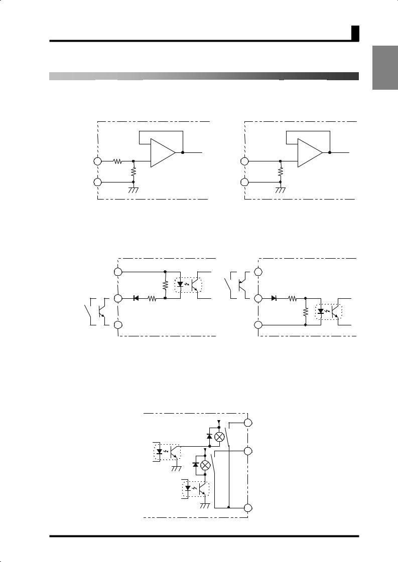
1.3 I/O Circuits
Input Circuit Diagrams
Analog Input
|
|
|
- |
|
|
|
|
- |
|
|
4 |
A |
|
To |
AD |
|
6 |
|
To AD |
Voltage |
|
+ |
Current |
+ |
|||||
|
|
|
|
||||||
|
|
|
B |
|
|
|
|
60Ω |
|
COM |
5 |
|
|
|
|
COM |
5 |
|
|
|
|
A+B = 1MΩ |
|
|
|
||||
|
|
|
|
|
|
|
|
|
Voltage input Current input
Event Input/Pulse Input
|
1 |
24VDC+ |
1 |
24VDC+ |
|
||
|
|
|
|
HOLD/ZERO |
4.7KΩ |
|
2.35KΩ |
Pulse |
3 |
|
3 |
|
|
||
|
2.35KΩ |
HOLD/ZERO |
|
|
|
Pulse |
4.7KΩ |
|
2 |
|
2 |
24VDC- |
|
24VDC- |
|
|
NPN input |
|
PNP input |
Output Circuit Diagrams
Contact Output
|
5V |
9 |
OUT1 |
|
|
||
5V |
|
11 |
OUT2 |
12 COM
5
INTRODUCTION

INTRODUCTION
CHAPTER 1 INTRODUCTION
Transistor Output
8.2Ω |
OUT1 |
12 |
COM |
9 |
|
|
|
8.2Ω |
PASS |
11 |
OUT2 |
10 |
8.2Ω |
|
|
|
|
|
|
8.2Ω |
OUT2 |
10 |
PASS |
11 |
8.2Ω |
|
|
|
|
|
|
12 |
COM |
9 |
OUT1 |
8.2Ω |
|
||
|
|
|
|
NPN output |
|
PNP output |
|
Linear Output
|
|
|
- |
+ |
- |
+ |
+ |
|
7 |
7 |
|
5KΩ min. L |
+ |
500Ω max. L |
|
- |
8 |
- 8 |
|
Linear voltage output Linear current output
Models with Normally Energized Relays K3GN-NDC-@-400 24 VDC
•The drive operation for the output relay is reversed in these models.
•Relay contacts can be made open (i.e., OFF) when comparative set values are being judged. This is effective when constructing systems that take failsafe measures into consideration.
List of Models
Models with Normally Energized Relays
K3GN-NDC-400 24 VDC
K3GN-NDC-FLK-400 24 VDC
K3GN-NDC-L1-400 24 VDC
K3GN-NDC-L2-400 24 VDC
Relation between Output Type and Relay Output Operation
Note: If Upper/Lower Limit is selected, the upper limit and lower limit for the comparative set value can be set individually and will be displayed for OUT1 and OUT2.
6
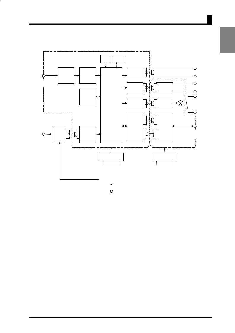
1.3 I/O Circuits
Internal Block Diagram
|
Key |
Display |
|
|
Transistor |
|
|
output |
Input circuit |
AD |
Drive circuit |
|
||
convertor |
|
|
|
|
Analog input |
|
Output |
*4 |
|
terminal |
Drive circuit |
Linear current/ |
||
|
|
circuit |
||
|
|
|
Voltage output |
|
|
EEPROM |
|
|
|
|
Microcomputer |
Output |
Contact |
|
|
Drive circuit |
|
||
|
circuit |
output |
*2 |
|
|
|
|||
|
Drive circuit |
Communi- |
|
|
|
cation |
|
|
|
Control |
Waveform |
driver |
Communi- |
|
input |
recitification |
|
||
circuit |
circuit |
|
cation |
|
Event input/ |
|
|
terminal |
*3 |
pulse input |
|
|
|
|
terminal |
|
|
|
|
|
Constant-voltage |
Constant-voltage |
|
|
|
circuit 1 |
circuit 2 |
|
|
INTRODUCTION
|
|
|
|
|
|
|
|
|
|
|
|
|
|
|
|
|
|
|
|
|
|
|
|
|
|
|
|
|
|
|
|
*1 Available only for the product with transistor output |
|||
|
|
|
|
|
||||
|
|
|
|
|
||||
|
Power supply |
|||||||
|
*2 Available only for the product with relay output |
|||||||
|
|
circuit |
||||||
|
|
|
|
|
*3 Available only for the product with communication interface |
|||
|
|
|
|
|
||||
|
|
|
|
|
||||
|
|
|
|
|
*4 Available only for the product with linear current/voltage output |
|||
|
|
Operation |
||||||
|
|
|
|
|
|
|||
|
|
power supply |
|
|
|
|
||
7
INTRODUCTION
CHAPTER 1 INTRODUCTION
1.4 Parts Name and Function
|
Operation indicator |
Operation indicator |
|
|
section |
Main indicator |
section |
|
|
K3GN |
|
Level |
OUT1 |
T |
ZERO |
SV |
8((((8 |
CMW |
|
|
OUT2 |
|
HOLD |
indicator
/ZERO |
|
|
|
|
Level key |
|
|
|
Mode key |
|
Shift key |
|
Up/Zero key |
|
|
|
|
|
|
|
|
|
|
|
|
|
|
|
|
|
|
|
|
|
|
|
|
|
|
|
|
|
|
|
|
|
|
|
|
|
|
Name |
|
|
|
|
Function |
|
|
|
||||
|
|
Main indicator |
|
|
Displays a process value, parameter code, or set value. |
|
|||||||||
|
|
|
|
OUT1 |
|
|
Is on when comparative output 1 is ON, and off when |
|
|||||||
|
|
|
(Comparative output 1) |
comparative output 1 is OFF. |
|
|
|
||||||||
|
|
|
|
OUT2 |
|
|
Is on when comparative output 2 is ON, and off when |
|
|||||||
|
|
|
(Comparative output 2) |
comparative output 2 is OFF. |
|
|
|
||||||||
|
|
|
|
SV |
|
|
Stays on while a set value is displayed or being changed, and off |
|
|||||||
|
|
|
|
(Set value) |
|
|
at all other times. |
|
|
|
|
|
|||
|
|
|
|
|
|
|
|
|
Stays on while a set value that can be taught is displayed, and |
|
|||||
|
|
|
|
T |
|
|
blinks during teaching. |
|
|
|
|||||
|
|
|
|
|
|
At the calibration level, stays on while a calibration value is |
|
||||||||
|
|
|
|
(Teaching) |
|
|
|
||||||||
|
Operation |
|
|
|
|
displayed, and blinks while the calibration value is read. |
|
||||||||
|
|
|
|
|
|
|
|
|
|||||||
|
|
|
|
|
|
|
|
Stays off at all other times. |
|
|
|
||||
|
indicator |
|
|
|
|
|
|
|
|
|
|
||||
|
|
|
ZERO |
|
|
Is on when zero-shifting by forced-zero operation is active. |
|
||||||||
|
sections |
|
|
|
|
|
|||||||||
|
|
|
(Forced-zero) |
|
|
Turns off when forced-zero operation is canceled. |
|
||||||||
|
|
|
|
|
|
|
|||||||||
|
|
|
|
HOLD |
|
|
Stays on while the process value is held, and off at all other times. |
|
|||||||
|
|
|
(Process value hold) |
|
|
|
|||||||||
|
|
|
|
|
|
|
|
|
|
|
|
||||
|
|
|
|
|
|
|
|
|
Is on while data reading and writing via communication interface |
|
|||||
|
|
|
|
CMW |
|
|
are both enabled. |
|
|
|
|
|
|||
|
|
|
|
|
|
Is off while data writing via communication interface is disabled. |
|
||||||||
|
|
|
(Communication |
|
|
Data reading is enabled even if this indicator is off provided that |
|
||||||||
|
|
|
|
writing) |
|
|
the product has the communication function. |
|
|||||||
|
|
|
|
|
|
|
|
|
If the product has no communication function, this indicator is |
|
|||||
|
|
|
|
|
|
|
|
|
always off. |
|
|
|
|
|
|
|
|
Level indicator |
|
|
Indicates the current level. |
|
|
|
|||||||
|
|
|
Level key |
|
Use to change one level to another. |
|
|
|
|||||||
|
|
|
Mode key |
|
|
Use to select a parameter. |
|
|
|
||||||
|
|
|
|
|
|
|
|
|
Use to check the set value of a parameter or enter the change state |
|
|||||
|
|
|
Shift key |
|
|
when the parameter is displayed. |
|
|
|
||||||
|
|
|
|
|
Use to select the digit that can be changed while shifting the set |
|
|||||||||
|
|
|
|
|
|
|
|
|
|
||||||
|
|
|
|
|
|
|
|
|
value. |
|
|
|
|
|
|
|
|
Up/Zero key |
|
|
Use to change the set value in the change state. |
|
|||||||||
|
|
|
|
Use to execute or cancel the forced-zero operation when a process |
|
||||||||||
|
|
|
|
|
|
|
|
|
value is displayed. |
|
|
|
|||
8

1.4 Parts Name and Function
CHAPTER
2INSTALLATION AND CONNECTION
This chapter describes how to install and connect the product before turning the power on.
2.1Installation 10
Dimensions/Panel Cutout Dimensions/
Installation Procedure
2.2I/O Terminal Connections 12
Terminal Arrangement/Terminal Connection
9
INSTALLATION CONNECTION AND
INSTALLATION AND CONNECTION
CHAPTER 2 Installation and Connection
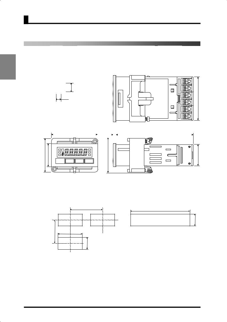
2.1 Installation
Dimensions
Size of characters displayed on the main indicator
8 |
7mm |
|
3.6mm |
44.8 |
|
|
||
48 |
|
3 |
|
|
|
|
80 |
||
|
|
|
|
||||||
|
|
|
|
|
|
|
|
|
|
|
|
|
|
|
|
|
|
|
|
35 |
24 |
(36.8) |
22 |
|
|
|
Units in mm |
Panel Cutout Dimensions
Separate mounting (units in mm)
60 min.
min. |
45 |
+0.6 |
40 |
-0 |
|
|
|
|
|
|
+0.3 -0 |
|
|
22.2 |
Gang mounting (units in mm)
(48 x No. of products -2.5)+1-0.0
+0.3 22.2 -0
The products cannot be made waterproof when gang-mounted.
Fit the product into a rectangular panel cutout, put the adapter on the product from the rear end all the way to the panel, and tighten the screws of the adapter to secure the product.
When gang-mounting the products, make sure the ambient temperature of the product falls within the specified limits.
Mount to a panel that is 1 to 5 mm thick. Mounting the product to a thinner panel will reduce the resistance to shock and vibration and may result in a malfunction of the product.
10
2.1 Installation
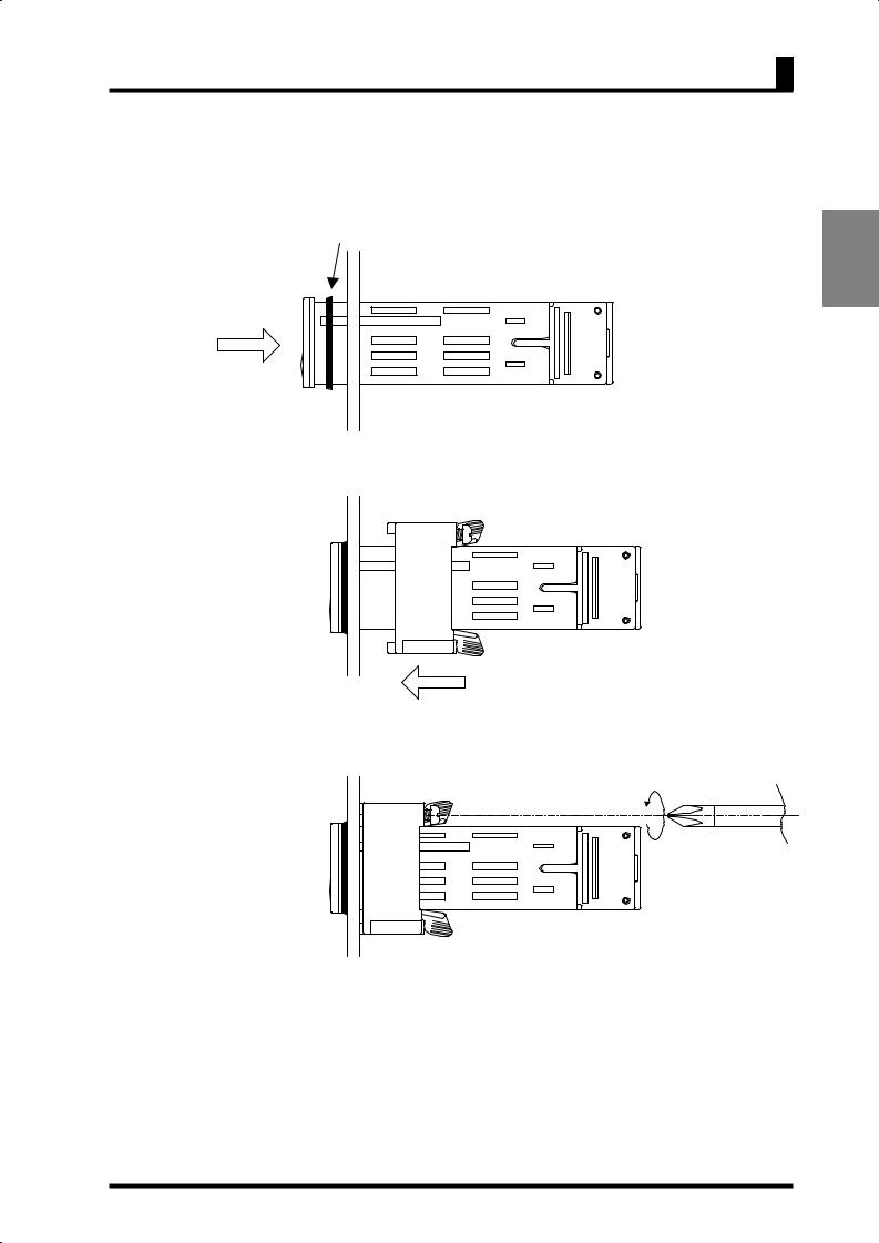
Installation Procedure
(1)Fit the product into a rectangular panel cutout.
(2)If you want to make the product waterproof, use the watertight packing as shown in the figure below.
Note that the watertight packing is direction-sensitive.
(3) Put the adapter on the product from the rear end all the way to the panel.
(4)Tighten the two screws of the adapter in alternate order to a tightening torque of 0.29 to 0.39 N·m.
11
INSTALLATION CONNECTION AND
CHAPTER 2 Installation and Connection
2.2 I/O Terminal Connections |
|
|
|
|
|
|
|
|
|
|||||||||
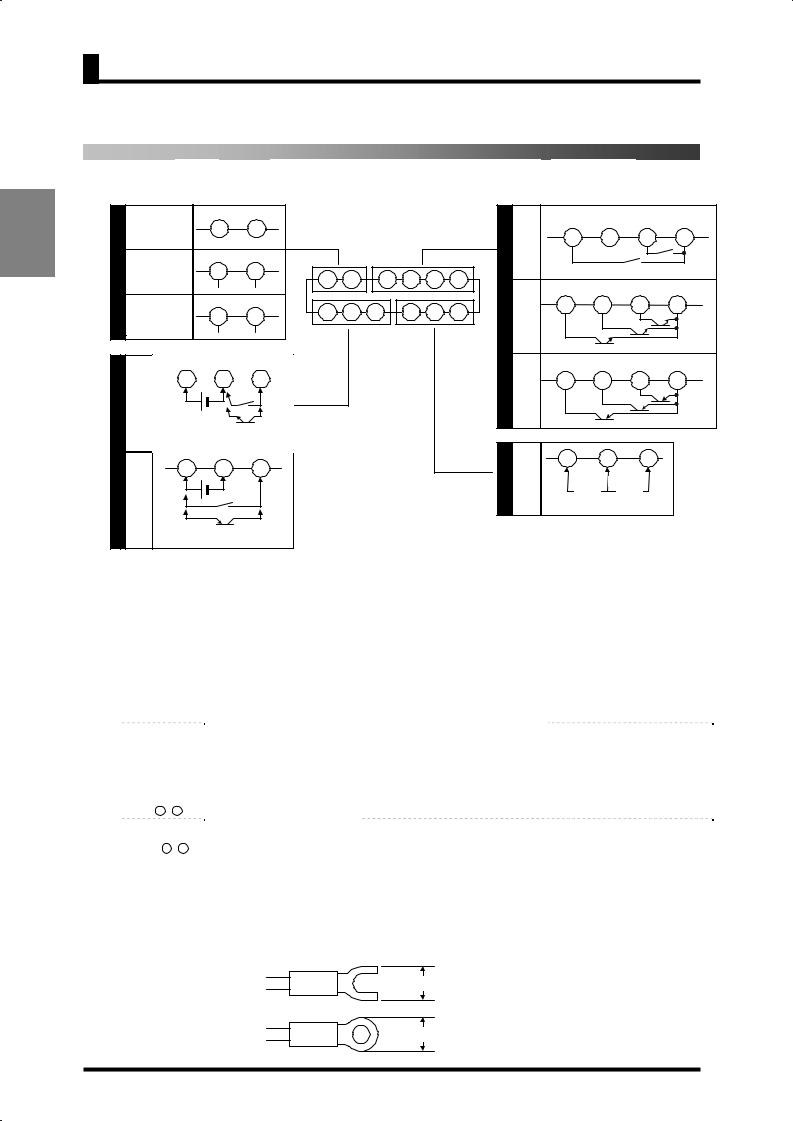
Terminal Arrangement |
|
|
|
|
|
|
|
|
|
|
|
|
|
|||||
INSTALLATION CONNECTIONAND |
communication |
NC |
NC |
|
|
|
|
|
|
|
|
|
|
|
|
|
|
|
|
Without |
7 |
8 |
|
|
|
|
|
|
|
|
|
|
OUT1 |
NC |
OUT2 |
COM |
|
|
communication |
|
|
|
|
|
|
|
|
|
Relay |
9 |
10 |
11 |
12 |
|||
|
function |
|
|
|
|
|
|
|
|
|
|
|
output |
|||||
|
|
|
|
|
|
|
|
|
|
|
|
|
|
|
|
|
|
|
|
|
With |
RS485 |
|
|
|
|
|
|
|
|
|
|
|
|
|
|
|
C |
|
7 |
8 |
C |
|
|
|
|
|
|
D |
|
|
|
|
|
|
|
function |
7 |
8 |
9 |
10 |
11 |
12 |
|
|
|
|
|
|
||||||
|
|
|
B (+) |
A (-) |
|
|
|
|
|
|
|
|
|
|
OUT1 |
PASS |
OUT2 |
COM |
|
|
|
Current/Voltage |
|
|
|
|
|
|
|
|
|
|
|||||
|
With linear |
|
1 |
2 |
3 |
4 |
5 |
6 |
|
|
NPN |
9 |
10 |
11 |
12 |
|||
|
7 |
8 |
|
|
|
tran- |
||||||||||||
|
|
output |
|
|
|
|
|
|
|
B |
D output |
|
|
|
|
|||
|
|
|
(+) |
(-) |
|
|
|
|
|
|
|
|
sistor |
|
|
|
|
|
|
|
1 |
2 |
3 |
|
|
|
|
|
|
|
|
|
|
OUT1 |
PASS |
OUT2 |
COM |
|
|
|
|
|
|
|
|
|
|
|
PNP |
9 |
10 |
11 |
12 |
|||
|
|
|
|
|
A |
|
|
|
|
|
|
|
|
tran- |
|
|
|
|
|
|
|
|
|
|
|
|
|
|
|
|
|
sistor |
|
|
|
|
|
|
NPN |
|
|
|
|
|
|
|
|
|
|
|
|
output |
|
|
|
|
|
input |
Control voltage |
|
|
|
|
|
|
|
|
|
|
|
|
|
|
|
|
|
|
24VDC |
Event input or |
|
|
|
|
|
|
|
|
|
|
|
|
|
|
|
|
|
|
pulse input |
|
|
|
|
|
|
|
|
|
|
|
|
|
|
|
A |
|
1 |
2 |
3 |
|
|
|
|
|
|
|
|
|
|
4 |
5 |
6 |
|
|
|
|
|
|
|
|
|
|
|
B |
Analog |
|
COM |
|
||||
|
|
|
|
|
|
|
|
|
|
|
|
|
|
|
||||
|
PNP |
Control |
|
|
|
|
|
|
|
|
|
|
input |
Voltage |
Current |
|
||
|
|
|
|
|
|
|
|
|
|
|
|
|
|
|||||
|
input |
voltage |
|
|
|
|
|
|
|
|
|
|
|
|
|
Analog input |
|
|
|
|
24VDC |
|
|
|
|
|
|
|
|
|
|
|
|
|
|
||
|
|
|
|
|
|
|
|
|
|
|
|
|
|
|
|
|
|
|
|
|
|
Event input or |
|
|
|
|
|
|
|
|
|
|
|
|
|
|
|
|
|
|
pulse input |
|
|
|
|
|
|
|
|
|
|
|
|
|
|
|
|
Terminal No. |
|
|
Name |
|
|
Description |
|
Applicable model |
|
|
- |
|
|
Operation power supply |
|
|
Operation power supply terminals |
|
All models |
|
|
|
|
|
|
|
|
Depending on parameter setting: |
|
|
|
|
|
|
|
|
|
|
• Hold the process value. |
|
|
|
|
|
|
|
Event input |
|
|
• Serve as input terminals for the |
|
|
|
|
- |
|
|
or |
|
|
forced-zero or forced-zero |
|
K3GN-ND_-_ 24VDC |
|
|
|
|
pulse contact/ |
|
|
cancel operation. |
|
|
||
|
|
|
|
|
|
|
|
|
||
|
|
|
|
input |
|
|
• Serve as pulse input terminals |
|
|
|
|
|
|
|
|
|
|
when the input type is set to |
|
|
|
|
- |
|
|
|
|
|
"pulse". |
|
K3GN-PD_-_ 24VDC |
|
|
|
|
|
|
|
|
|
|
||
|
- |
|
|
Analog input |
|
Voltage/current analog terminals |
All models |
|
||
|
- |
|
|
Communication |
|
|
RS-485 communication terminals |
|
K3GN-_D_-FLK 24VDC |
|
|
|
|
Linear current output |
|
|
Linear current output |
|
K3GN-___-L1 24VDC |
|
|
|
|
|
|
Linear voltage output |
|
|
Linear voltage output |
|
K3GN-___-L2 24VDC |
|
|
11 -12 |
|
|
|
|
|
Provide comparative output. |
|
K3GN-_DC-_ 24VDC |
|
|
|
|
|
Comparative output |
|
|
Provide PASS output in addition |
|
|
|
|
11 -12 |
|
|
|
|
to OUT1/OUT2 (comparative |
|
K3GN-NDT1-_ 24VDC |
|
|
|
|
|
|
|
|
output 1/2) when the product is of |
|
K3GN-PDT2-_ 24VDC |
|
|
|
|
|
|
|
|
|
|
|
||
|
|
|
|
|
|
|
transistor output type. |
|
|
|
Terminal Connection
Wire the terminals using M3 crimp contacts of the type shown below.
5.8 mm max
5.8 mm max
12
2.2 I/O Terminal Connections
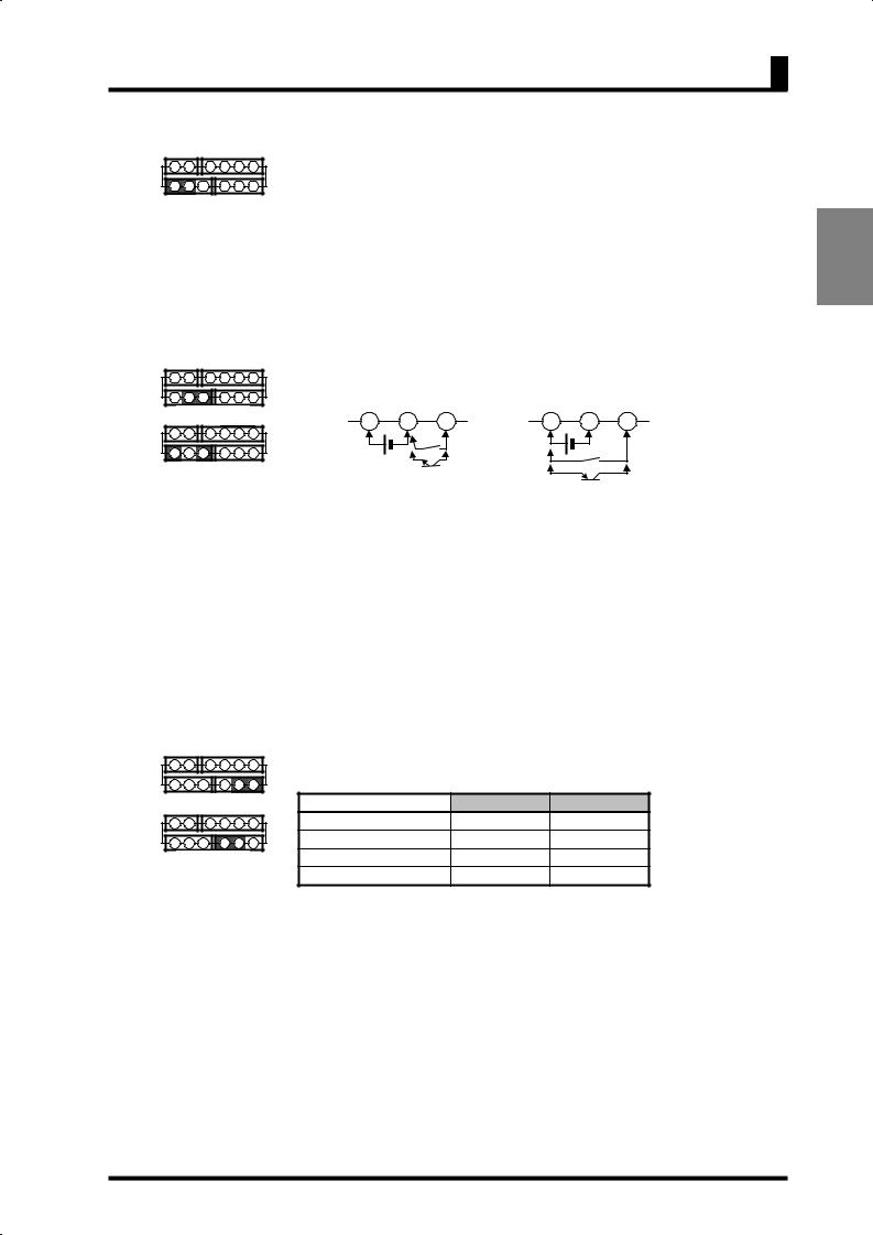
Power Supply
7 8 9 10 11 12
1 |
2 |
3 |
4 |
5 |
6 |
Connect the following power supply to terminals and . Supply voltage: 24VDC
Operating voltage range: 85 to 110% of the rated voltage Power consumption: 2.5W (at max. load)
Note that, when turned on, the product will require the operation power supply to have more power supply capacity than rated.
If multiple products are used, the power supply must be able to afford to supply power to the products.
Event Input or Pulse Input |
|
|
|
|
|
||||||
7 |
8 |
|
9 10 11 12 |
Apply the event or pulse signal to terminals |
and |
if the product is of NPN |
|||||
1 |
2 |
3 |
4 |
5 |
6 |
input type, or terminals |
and |
if the product is of PNP input type. |
|||
|
|
|
|
|
|
||||||
|
NPN input |
|
1 |
2 |
3 |
1 |
2 |
3 |
|||
7 |
8 |
|
9 10 11 12 |
||||||||
|
|
|
|
Control power |
|
|
|||||
1 |
2 |
3 |
4 |
5 |
6 |
Control power |
|
|
|
||
|
24VDC |
|
|
||||||||
|
PNP input |
|
24VDC |
Event or |
|
|
|
||||
|
|
|
|
|
|
|
|
|
|
||
|
|
|
|
|
|
|
pulse input |
|
Event or |
|
|
|
|
|
|
|
|
|
|
|
|
|
|
|
|
|
|
|
|
|
|
|
|
pulse input |
|
|
|
|
|
|
|
|
NPN input type |
PNP input type |
|
||
|
|
|
|
|
|
|
|
|
|
||
The input equipment connected to these terminals must meet the following conditions.
Transistor output |
ON residual current: |
2.5V max. |
|
OFF leakage current: |
0.1 mA max. |
|
Current leakage with |
|
|
transistor turned ON: |
15 mA min. |
Relay output |
Load current: |
5 mA max. |
Analog Input |
|
|
|
|||||
7 |
8 |
|
9 10 11 12 |
The following table shows the analog ranges and applicable analog input |
||||
1 |
2 |
3 |
4 |
5 |
6 |
terminals. |
|
|
|
Current input |
Analog range |
Positive side |
Negative side |
||||
7 |
8 |
|
9 10 11 12 |
4 to 20 mA/0 to 20 mA |
|
|
||
1 |
2 |
3 |
4 |
5 |
6 |
1 to 5V/0 to 5V |
|
|
|
Voltage input |
±5V |
|
|
||||
|
|
|
|
|
|
±10V |
|
|
The maximum absolute ratings for analog input are as follows.
Be careful that these ratings must not be exceeded even for a moment.
4 to 20 mA/0 to 20 mA: |
±30 mA |
1 to 5V/0 to 5V: |
±13.5V |
±5V: |
±13.5V |
±10V: |
±26V |
INSTALLATION CONNECTION AND
13
INSTALLATION AND CONNECTION
CHAPTER 2 Installation and Connection
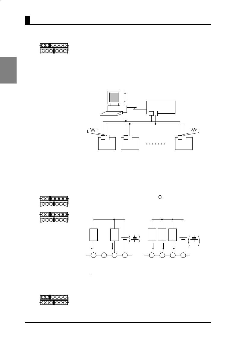
Communication
7 |
8 |
|
9 |
10 11 12 |
||
1 |
2 |
3 |
|
4 |
5 |
6 |
Connect the communication cable to terminals |
and |
if using the |
communication function. |
|
|
RS-485 connections can be one-to-one or one-to N. A maximum of 32 units (including the host computer) can be connected in one-to-N systems.
The total length of the communication cables should be up to 500 m.
Use shielded twisted-pair cables (AWG 28 or thicker) as the communication cables.
Be sure to turn ON the terminator switches only in the devices at each end of the transmission line.
RS232C RS232C-RS485 interface convertor
 + -
+ -
Terminator 120Ω(1/2Ω)
(
7 |
8 |
7 |
8 |
7 |
8 |
(B) (A) |
|
(B) (A) |
|
(B) (A) |
|
|
|
|
Terminator 120Ω(1/2Ω)
(
K3GN |
|
K3GN |
|
K3GN |
(No. 1) |
|
(No. 2) |
|
(No. 31) |
|
|
|
|
|
Match the communications format of the K3GN and the host computer. If a one-to-N system is being used, be sure that the communications formats of all devices in the system (except individual unit numbers) are the same.
Chapter 7 explains how to set the K3GN communication format. Refer to your computer's manual for details on changing its communications settings.
Comparative Output
7 |
8 |
|
9 10 11 12 |
Comparative output is produced at terminals |
to 12 . |
|
|
|||||
1 |
2 |
3 |
4 |
5 |
6 |
If the product is of relay output type, terminal |
is not used. |
|
||||
Transistor output |
Loads connected to the product and the power supply for the loads must be rated |
|||||||||||
|
|
|
|
|
|
|||||||
7 |
8 |
|
9 10 11 12 |
as follows. |
|
|
|
|
|
|
||
1 |
2 |
3 |
4 |
5 |
6 |
|
|
max. |
|
|
|
max. |
|
Relay output |
|
|
|
|
|
||||||
|
|
|
|
|
|
Load |
Load |
30VDC |
Load |
Load |
Load |
24VDC |
|
|
|
|
|
|
1A max. |
1A max. |
|
50 mA max. |
50 mA max. |
50 mA max. |
PNP |
|
|
|
|
|
|
|
|
|||||
9 |
10 |
11 |
12 |
9 |
10 |
11 |
12 |
OUT1 |
NC |
OUT2 COM |
OUT1 PASS OUT2 COM |
||||
Relay output type |
|
Transistor output type |
|||||
The  connection causes the current to flow in the direction opposite to indicated by the arrows.
Linear Output
7 |
8 |
|
9 |
10 11 12 |
Linear currents and voltages are output between terminals 7 to 8. Contact a load |
1 |
2 |
3 |
|
4 5 6 |
within the specified range. |
14

2.2 I/O Terminal Connections
CHAPTER
3APPLICATION EXAMPLES
This chapter shows some examples of product applications.
3.1Monitoring the Remaining Quantity of Soup 16
3.2Monitoring the Load Current of a Motor 18
3.3Monitoring the Quantity of Dust 20
3.4Monitoring the Internal Pressure of a Tank 22
3.5Monitoring the Rotational Speed of a Motor 24
3.6Using the Product as a Digital Indicator for PLC 26
15
APPLICATION EXAMPLES
CHAPTER 3 APPLICATION EXAMPLES
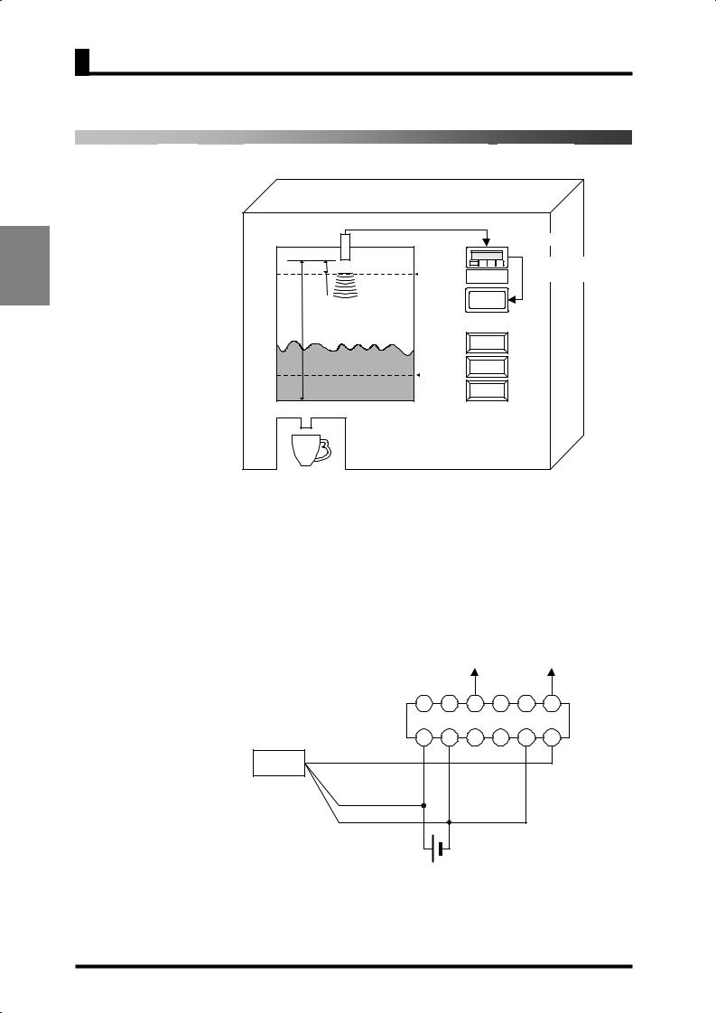
3.1 Monitoring the Remaining Quantity of Soup
Application
APPLICATION EXAMPLES
Ultrasonic sensor |
4 to 20mA |
|
|
|
|
E4PA-LS50-M1 |
|
K3GN-NDC |
60mm ~ 500mm |
|
Comparative output 1 |
100% |
Remaining |
(lower-limit action) |
60mm |
quantity of soup |
|
Replenish |
|
|
500mm |
Cup (L) |
|
|
|
|
20% |
Cup (M) |
|
|
|
|
|
Cup (S) |
|
•The remaining quantity of soup is monitored.
•The soup level is measured with an ultrasonic displacement sensor.
•The K3GN indicates the remaining quantity of soup on a percentage basis.
•Four measurements are averaged for stable indication.
•Comparative output 1 is produced as a lower-limit action signal. When the remaining quantity of soup reaches 20% (lower limit), the “Replenish” indicator turns on.
Wiring
Comparative output 1
|
|
|
|
|
|
|
COM |
|
|
|
7 |
8 |
9 |
10 |
11 |
12 |
|
Ultrasonic displacement |
|
|
K3GN-NDC |
|
|
|||
1 |
2 |
3 |
4 |
5 |
6 |
|||
sensor |
|
|||||||
|
|
|
|
COM |
Current |
|||
|
Black4 to 20mA |
|
|
|
||||
|
|
|
|
|
|
input |
||
|
|
|
|
|
|
|
||
|
Brown (+) |
|
|
|
|
|
|
|
|
Blue (-) |
|
|
|
|
|
|
|
|
Operation |
|
|
24VDC |
|
|
|
|
|
power supply |
|
|
|
|
|
||
16
3.1 Monitoring the Remaining Quantity of Soup
Parameter Setting
Operation
Set the parameters of the K3GN as follows.
|
Level |
|
|
Parameter |
|
Set value |
|
|
|
|
|
in-t |
|
analg |
|
|
|
|
|
range |
|
4-20 |
|
|
|
|
|
inp.1 |
|
4.00 |
|
|
Initial setting |
|
|
dsp.1 |
|
100 |
|
|
|
|
inp.2 |
|
20.00 |
|
|
|
|
|
|
|
|
||
|
|
|
|
dsp.2 |
|
0 |
|
|
|
|
|
dp |
|
,,,,, |
|
|
|
|
|
out1.t |
|
lo |
|
|
Advanced-function setting |
|
|
avg |
|
4 |
|
|
Operation setting |
|
|
out1 |
|
20 |
|
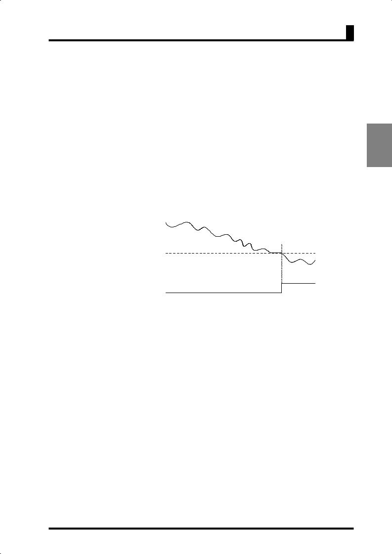
Set the analog output characteristic mode of the sensor to “decrease”. For details on sensor setting, refer to the Operation Manual for the sensor.
Remaining quantity of soup
OUT1 lower limit value (20)
Comparative
output 1
•Comparative output 1 turns on when the remaining quantity of soup decreases to 20%.
17
APPLICATION EXAMPLES
Loading...