


 Loading...
Cat. No. I539-E1-02
USER’S MANUAL
DeviceNet Communications Unit
MODEL 3G3MV-PDRT2
(For SYSDRIVE 3G3MV Multi-function Compact Inverters)
DeviceNet Communications Card
MODEL 3G3RV-PDRT2
(For SYSDRIVE 3G3RV and 3G3FV High-function General-purpose Inverters)

Thank you for choosing a 3G3MV/3G3RV Series Inverter and DeviceNet Communications Unit. This manual describes the specifications and operating methods of the DeviceNet Communications Unit used for exchanging data between an Inverter and a Programmable Controller. Specifically, it describes the operation methods, communications methods, and data setting methods of the 3G3MV-PDRT2 DeviceNet Communications Unit and 3G3RV-PDRT2 DeviceNet Communications Card. Proper use and handling of the product will help ensure proper product performance, will lengthen product life, and may prevent possible accidents.
Please read this manual thoroughly and handle and operate the product with care.
For details about the 3G3MV Inverter and DeviceNet communications system, refer to the following reference manuals.
Inverter Manuals DeviceNet Manuals
1.To ensure safe and proper use of the OMRON Inverters, please read this USER’S MANUAL (Cat. No. I539-E1) to gain sufficient knowledge of the devices, safety information, and precautions before actual use.
2.The products are illustrated without covers and shieldings for closer look in this USER’S MANUAL. For actual use of the products, make sure to use the covers and shieldings as specified.
3.This USER’S MANUAL and other related user’s manuals are to be delivered to the actual end users of the products.
4.Please keep this manual close at hand for future reference.
5.If the product has been left unused for a long time, please inquire at our sales representative.
NOTICE
1.This manual describes the functions of the product and relations with other products. You should assume that anything not described in this manual is not possible.
2.“PLC” in this manual refers to the SYSMAC CS/CJ-series, C200HX/HG/HE, and CV-series Programmable Controllers that can be connected to a DeviceNet System. (C200HS Programmable Controllers support only the remote I/O function.)
3.Although care has been given in documenting the product, please contact your OMRON representative if you have any suggestions on improving this manual.
4.The product contains potentially dangerous parts under the cover. Do not attempt to open the cover under any circumstances. Doing so may result in injury or death and may damage the product. Never attempt to repair or disassemble the product.
5.We recommend that you add the following precautions to any instruction manuals you prepare for the system into which the product is being installed.
•Precautions on the dangers of high-voltage equipment.
•Precautions on touching the terminals of the product even after power has been turned off. (These terminals are live even with the power turned off.)
6.Inverter and Option Unit wiring and Digital Operator operations must be performed by somebody with a specialist knowledge of electrical systems.
7.The individual life expectancies of the Inverter's internal components must be considered. Perform maintenance, such as Unit replacement, appropriate for the operating conditions.
8.Specifications and functions may be changed without notice in order to improve product performance.
Items to Check Before Unpacking
Check the following items before removing the product from the package:
•Has the correct product been delivered (i.e., the correct model number and specifications)?
•Has the product been damaged in shipping?
•Are any screws or bolts loose?
•Have all accessories been delivered together with or attached to the product?

USER’S MANUAL
DeviceNet Communications Unit
MODEL 3G3MV-PDRT2
(For SYSDRIVE 3G3MV Multi-function Compact Inverters)
DeviceNet Communications Card
MODEL 3G3RV-PDRT2
(For SYSDRIVE 3G3RV and 3G3FV High-function General-purpose Inverters)
Notice:
OMRON products are manufactured for use according to proper procedures by a qualified operator and only for the purposes described in this manual.
The following conventions are used to indicate and classify precautions in this manual. Always heed the information provided with them. Failure to heed precautions can result in injury to people or damage to property.
!DANGER Indicates an imminently hazardous situation which, if not avoided, will result in death or serious injury. Additionally, there may be severe property damage.
!WARNING Indicates a potentially hazardous situation which, if not avoided, could result in death or serious injury. Additionally, there may be severe property damage.
!Caution Indicates a potentially hazardous situation which, if not avoided, may result in minor or moderate injury, or property damage.
OMRON Product References
All OMRON products are capitalized in this manual. The word “Unit” is also capitalized when it refers to an OMRON product, regardless of whether or not it appears in the proper name of the product.
The abbreviation “Ch,” which appears in some displays and on some OMRON products, often means “word” and is abbreviated “Wd” in documentation in this sense.
The abbreviation “PLC” means Programmable Controller. The abbreviation “PC,” however, is used in some Programming Device displays to mean Programmable Controller.
Visual Aids
The following headings appear in the left column of the manual to help you locate different types of information.
Note Indicates information of particular interest for efficient and convenient operation of the product.
OMRON, 2003
All rights reserved. No part of this publication may be reproduced, stored in a retrieval system, or transmitted, in any form, or by any means, mechanical, electronic, photocopying, recording, or otherwise, without the prior written permission of OMRON.
No patent liability is assumed with respect to the use of the information contained herein. Moreover, because OMRON is constantly striving to improve its high-quality products, the information contained in this manual is subject to change without notice. Every precaution has been taken in the preparation of this manual. Nevertheless, OMRON assumes no responsibility for errors or omissions. Neither is any liability assumed for damages resulting from the use of the information contained in this publication.
■ General Precautions
The user must operate the product according to the performance specifications described in the operation manuals.
Before using the product under conditions which are not described in the manual or applying the product to nuclear control systems, railroad systems, aviation systems, vehicles, combustion systems, medical equipment, amusement machines, safety equipment, and other systems, machines, and equipment that may have a serious influence on lives and property if used improperly, consult your OMRON representative.
Make sure that the ratings and performance characteristics of the product are sufficient for the systems, machines, and equipment, and be sure to provide the systems, machines, and equipment with double safety mechanisms.
■ Transportation, Installation, Wiring, and Maintenance Precautions
!WARNING Do not touch the conductive parts such as internal PCBs or terminal blocks while power is being supplied. Doing so may result in electrical shock.
!WARNING Turn ON the input power supply only after mounting the front cover, terminal covers, bottom cover, Operator, and optional items. Leave them mounted in place while power is being supplied. Not doing so may result in electrical shock, malfunction, or damage to the product.
!WARNING Wiring, maintenance, or inspection must be performed by authorized personnel. Not doing so may result in electrical shock or fire.
!WARNING Wiring, maintenance, or inspection must be performed after turning OFF the power supply, confirming that the CHARGE indicator (or status indicators) is OFF, and after waiting for the time specified on the Inverter front cover. Not doing so may result in electrical shock.
!WARNING Do not damage, pull on, apply stress to, place heavy objects on, or pinch the cables. Doing so may result in electrical shock, operation stoppage, or burning.
!WARNING Install devices to stop operation as required to ensure safety. Equipment damage may result. This is particularly important when operation is set to continue for communications errors because the Inverter will continue operation.
!WARNING Do not attempt to disassemble or repair the Unit. Doing either of these may result in electrical shock, injury, or damage to the product.
!Caution Do not store, install, or operate the product in the following places. Doing so may result in electrical shock, fire or damage to the product.
•Locations subject to direct sunlight.
•Locations subject to temperatures or humidity outside the range specified in the specifications.
•Locations subject to condensation as the result of severe changes in temperature.
•Locations subject to corrosive or flammable gases.
•Locations subject to exposure to combustibles.
•Locations subject to dust (especially iron dust) or salts.
•Locations subject to exposure to water, oil, or chemicals.
•Locations subject to shock or vibration.
!Caution Do not allow foreign objects to enter inside the product. Doing so may result in fire or malfunction.
!Caution Do not apply any strong impact. Doing so may result in damage to the product or malfunction.
!Caution Be sure to wire correctly and securely. Not doing so may result in injury or damage to the product.
!Caution Be sure to firmly tighten the screws on the terminal block. Not doing so may result in fire, injury, or damage to the product.
!Caution Carefully handle the product because it uses semiconductor elements. Careless handling may result in malfunction.
!Caution Take appropriate and sufficient countermeasures when installing systems in the following locations. Not doing so may result in equipment damage.
•Locations subject to static electricity or other forms of noise.
•Locations subject to strong electromagnetic fields and magnetic fields.
•Locations subject to possible exposure to radioactivity.
•Locations close to power supplies.
■Operation and Adjustment Precautions
!Caution Do not carelessly change Inverter's settings. Doing so may result in injury or damage to the product.
!Caution Install devices to stop operation as required to ensure safety. Equipment damage may result. This is particularly important when operation is set to continue for communications errors because the Inverter will continue operation.
!Caution Be sure to perform the setting switch settings correctly and confirm the settings before starting operation. Not doing so may result in malfunction or damage to the product.
■ Reference Manuals
Information on connected devices is required to operate the DeviceNet Communications Unit/Card. Refer to the following manuals for information on related products.
Inverter Manuals
Name |
Cat. No. |
|
|
SYSDRIVE 3G3MV Multi-function Compact Inverters |
I527 |
User’s Manual |
|
|
|
SYSDRIVE 3G3RV High-function General-purpose |
I532 |
Inverters User’s Manual |
|
|
|
SYSDRIVE 3G3FV High-function General-purpose |
I516 |
Inverters User’s Manual |
|
|
|
Note Refer to the user’s manual for the Inverter for information on Inverter operation.
DeviceNet Manuals
Name |
Cat. No. |
|
|
DeviceNet Operation Manual |
W267 |
|
|
DeviceNet Configurator Operation Manual (Version 2.@) |
W382 |
CS/CJ Series DeviceNet Unit Operation Manual |
W380 |
|
|
DeviceNet DRT2 Series Slaves Operation Manual |
W404 |
|
|
Note Refer to the DeviceNet Operation Manual for details on the DeviceNet network.

Read and Understand this Manual
Please read and understand this manual before using the product. Please consult your OMRON representative if you have any questions or comments.
Warranty and Limitations of Liability
WARRANTY
OMRON's exclusive warranty is that the products are free from defects in materials and workmanship for a period of one year (or other period if specified) from date of sale by OMRON.
OMRON MAKES NO WARRANTY OR REPRESENTATION, EXPRESS OR IMPLIED, REGARDING NONINFRINGEMENT, MERCHANTABILITY, OR FITNESS FOR PARTICULAR PURPOSE OF THE PRODUCTS. ANY BUYER OR USER ACKNOWLEDGES THAT THE BUYER OR USER ALONE HAS DETERMINED THAT THE PRODUCTS WILL SUITABLY MEET THE REQUIREMENTS OF THEIR INTENDED USE. OMRON DISCLAIMS ALL OTHER WARRANTIES, EXPRESS OR IMPLIED.
LIMITATIONS OF LIABILITY
OMRON SHALL NOT BE RESPONSIBLE FOR SPECIAL, INDIRECT, OR CONSEQUENTIAL DAMAGES, LOSS OF PROFITS OR COMMERCIAL LOSS IN ANY WAY CONNECTED WITH THE PRODUCTS, WHETHER SUCH CLAIM IS BASED ON CONTRACT, WARRANTY, NEGLIGENCE, OR STRICT LIABILITY.
In no event shall the responsibility of OMRON for any act exceed the individual price of the product on which liability is asserted.
IN NO EVENT SHALL OMRON BE RESPONSIBLE FOR WARRANTY, REPAIR, OR OTHER CLAIMS REGARDING THE PRODUCTS UNLESS OMRON'S ANALYSIS CONFIRMS THAT THE PRODUCTS WERE PROPERLY HANDLED, STORED, INSTALLED, AND MAINTAINED AND NOT SUBJECT TO CONTAMINATION, ABUSE, MISUSE, OR INAPPROPRIATE MODIFICATION OR REPAIR.

Application Considerations
SUITABILITY FOR USE
OMRON shall not be responsible for conformity with any standards, codes, or regulations that apply to the combination of products in the customer's application or use of the products.
At the customer's request, OMRON will provide applicable third party certification documents identifying ratings and limitations of use that apply to the products. This information by itself is not sufficient for a complete determination of the suitability of the products in combination with the end product, machine, system, or other application or use.
The following are some examples of applications for which particular attention must be given. This is not intended to be an exhaustive list of all possible uses of the products, nor is it intended to imply that the uses listed may be suitable for the products:
•Outdoor use, uses involving potential chemical contamination or electrical interference, or conditions or uses not described in this manual.
•Nuclear energy control systems, combustion systems, railroad systems, aviation systems, medical equipment, amusement machines, vehicles, safety equipment, and installations subject to separate industry or government regulations.
•Systems, machines, and equipment that could present a risk to life or property.
Please know and observe all prohibitions of use applicable to the products.
NEVER USE THE PRODUCTS FOR AN APPLICATION INVOLVING SERIOUS RISK TO LIFE OR PROPERTY WITHOUT ENSURING THAT THE SYSTEM AS A WHOLE HAS BEEN DESIGNED TO ADDRESS THE RISKS, AND THAT THE OMRON PRODUCTS ARE PROPERLY RATED AND INSTALLED FOR THE INTENDED USE WITHIN THE OVERALL EQUIPMENT OR SYSTEM.
PROGRAMMABLE PRODUCTS
OMRON shall not be responsible for the user's programming of a programmable product, or any consequence thereof.
Disclaimers
CHANGE IN SPECIFICATIONS
Product specifications and accessories may be changed at any time based on improvements and other reasons.
It is our practice to change model numbers when published ratings or features are changed, or when significant construction changes are made. However, some specifications of the products may be changed without any notice. When in doubt, special model numbers may be assigned to fix or establish key specifications for your application on your request. Please consult with your OMRON representative at any time to confirm actual specifications of purchased products.
DIMENSIONS AND WEIGHTS
Dimensions and weights are nominal and are not to be used for manufacturing purposes, even when tolerances are shown.
PERFORMANCE DATA
Performance data given in this manual is provided as a guide for the user in determining suitability and does not constitute a warranty. It may represent the result of OMRON's test conditions, and the users must correlate it to actual application requirements. Actual performance is subject to the OMRON Warranty and Limitations of Liability.
ERRORS AND OMISSIONS
The information in this manual has been carefully checked and is believed to be accurate; however, no responsibility is assumed for clerical, typographical, or proofreading errors, or omissions.

Table of Contents
. . . . . . . . . . . . . . .Chapter 1. Functions and System Configuration |
1-1 |
|
1-1 |
Functions . . . . . . . . . . . . . . . . . . . . . . . . . . . . . . . . . . . . . . . . . . . . . . . . . . . . . . . . . . . . . . . . |
1-2 |
1-2 Overview of Smart Slave Functions. . . . . . . . . . . . . . . . . . . . . . . . . . . . . . . . . . . . . . . . . . . . |
1-5 |
|
1-3 |
Comparison to Earlier Models . . . . . . . . . . . . . . . . . . . . . . . . . . . . . . . . . . . . . . . . . . . . . . . . |
1-8 |
1-4 |
DeviceNet Features . . . . . . . . . . . . . . . . . . . . . . . . . . . . . . . . . . . . . . . . . . . . . . . . . . . . . . . . |
1-11 |
1-5 |
DeviceNet System Configuration. . . . . . . . . . . . . . . . . . . . . . . . . . . . . . . . . . . . . . . . . . . . . . |
1-13 |
. . . . . . . . . . . . . . . . . . . . . . . . .Chapter 2. Example System Startup |
2-1 |
|
2-1 Basic Procedures and Configuration Examples . . . . . . . . . . . . . . . . . . . . . . . . . . . . . . . . . . . |
2-2 |
|
2-2 |
Preparations . . . . . . . . . . . . . . . . . . . . . . . . . . . . . . . . . . . . . . . . . . . . . . . . . . . . . . . . . . . . . . |
2-4 |
2-3 |
Setting and Wiring Hardware . . . . . . . . . . . . . . . . . . . . . . . . . . . . . . . . . . . . . . . . . . . . . . . . . |
2-6 |
2-4 |
Starting Communications . . . . . . . . . . . . . . . . . . . . . . . . . . . . . . . . . . . . . . . . . . . . . . . . . . . . |
2-10 |
2-5 |
Checking Operation . . . . . . . . . . . . . . . . . . . . . . . . . . . . . . . . . . . . . . . . . . . . . . . . . . . . . . . . |
2-13 |
. . . . . . . . . . . . . . . . . . . . . . . . . . . . . . .Chapter 3. Setup and Wiring |
3-1 |
|
3-1 |
Nomenclature and Settings. . . . . . . . . . . . . . . . . . . . . . . . . . . . . . . . . . . . . . . . . . . . . . . . . . . |
3-2 |
3-2 |
Installation and Wiring . . . . . . . . . . . . . . . . . . . . . . . . . . . . . . . . . . . . . . . . . . . . . . . . . . . . . . |
3-6 |
3-3 |
Communications Line Noise Prevention . . . . . . . . . . . . . . . . . . . . . . . . . . . . . . . . . . . . . . . . |
3-20 |
3-4 |
Conformity to EC Directives . . . . . . . . . . . . . . . . . . . . . . . . . . . . . . . . . . . . . . . . . . . . . . . . . |
3-25 |
. . . . . . . . . . . . . . . . . . . . .Chapter 4. SYSDRIVE Inverter Settings |
4-1 |
|
4-1 |
SYSDRIVE 3G3MV Settings . . . . . . . . . . . . . . . . . . . . . . . . . . . . . . . . . . . . . . . . . . . . . . . . |
4-2 |
4-2 |
SYSDRIVE 3G3RV and 3G3PV Settings . . . . . . . . . . . . . . . . . . . . . . . . . . . . . . . . . . . . . . . |
4-6 |
4-3 |
SYSDRIVE 3G3FV Settings . . . . . . . . . . . . . . . . . . . . . . . . . . . . . . . . . . . . . . . . . . . . . . . . . |
4-10 |
. . . . . . . . . . . . . . . . . . . . . . . . . . . .Chapter 5. Remote I/O Functions |
5-1 |
|
5-1 Overview of Remote I/O Functions . . . . . . . . . . . . . . . . . . . . . . . . . . . . . . . . . . . . . . . . . . . . |
5-2 |
|
5-2 Switching the Remote I/O Function . . . . . . . . . . . . . . . . . . . . . . . . . . . . . . . . . . . . . . . . . . . . |
5-5 |
|
5-3 |
Basic Remote I/O . . . . . . . . . . . . . . . . . . . . . . . . . . . . . . . . . . . . . . . . . . . . . . . . . . . . . . . . . . |
5-9 |
5-4 |
Standard Remote I/O . . . . . . . . . . . . . . . . . . . . . . . . . . . . . . . . . . . . . . . . . . . . . . . . . . . . . . . |
5-12 |
5-5 Special Remote I/O Operation . . . . . . . . . . . . . . . . . . . . . . . . . . . . . . . . . . . . . . . . . . . . . . . . |
5-15 |
|
5-6 |
Control Remote I/O Operation . . . . . . . . . . . . . . . . . . . . . . . . . . . . . . . . . . . . . . . . . . . . . . . . |
5-20 |
5-7 |
Unit Status . . . . . . . . . . . . . . . . . . . . . . . . . . . . . . . . . . . . . . . . . . . . . . . . . . . . . . . . . . . . . . . |
5-30 |
. . . . . . . . . . . . . . . . . . . . . . . .Chapter 6. Message Communications |
6-1 |
|
6-1 Overview of Message Communications. . . . . . . . . . . . . . . . . . . . . . . . . . . . . . . . . . . . . . . . . |
6-2 |
|
6-2 Sending Messages from an OMRON PLC. . . . . . . . . . . . . . . . . . . . . . . . . . . . . . . . . . . . . . . |
6-4 |
|
6-3 Overview of Messages and Responses. . . . . . . . . . . . . . . . . . . . . . . . . . . . . . . . . . . . . . . . . . |
6-7 |
|
6-4 |
Motor Data Objects: Class 28 Hex. . . . . . . . . . . . . . . . . . . . . . . . . . . . . . . . . . . . . . . . . . . . . |
6-8 |
6-5 |
Control Supervisor Objects: Class 29 Hex. . . . . . . . . . . . . . . . . . . . . . . . . . . . . . . . . . . . . . . |
6-10 |
6-6 |
AC/DC Drive Objects: Class 2A Hex . . . . . . . . . . . . . . . . . . . . . . . . . . . . . . . . . . . . . . . . . . |
6-13 |
6-7 |
Reading and Writing Parameters: Class 64 Hex. . . . . . . . . . . . . . . . . . . . . . . . . . . . . . . . . . . |
6-18 |

Table of Contents
. . . . . . . . . . . . . . . . . . . . . . . . . . . .Chapter 7. Configurator Settings |
7-1 |
|
7-1 |
Basic Configurator Operations . . . . . . . . . . . . . . . . . . . . . . . . . . . . . . . . . . . . . . . . . . . . . . . . |
7-2 |
7-2 |
Smart Slave Functions . . . . . . . . . . . . . . . . . . . . . . . . . . . . . . . . . . . . . . . . . . . . . . . . . . . . . . |
7-9 |
7-3 Edit Device Parameters Window . . . . . . . . . . . . . . . . . . . . . . . . . . . . . . . . . . . . . . . . . . . . . . |
7-48 |
|
7-4 |
Monitor Device Window. . . . . . . . . . . . . . . . . . . . . . . . . . . . . . . . . . . . . . . . . . . . . . . . . . . . . |
7-55 |
7-5 |
Maintenance Information Window . . . . . . . . . . . . . . . . . . . . . . . . . . . . . . . . . . . . . . . . . . . . . |
7-63 |
. . . . . . . . . . . . . . . . . . . . . . . . . .Chapter 8. Communications Errors |
8-1 |
|
8-1 |
Communications Line Errors . . . . . . . . . . . . . . . . . . . . . . . . . . . . . . . . . . . . . . . . . . . . . . . . . |
8-2 |
8-2 |
Message Communications Errors . . . . . . . . . . . . . . . . . . . . . . . . . . . . . . . . . . . . . . . . . . . . . . |
8-4 |
8-3 Special Remote I/O Errors . . . . . . . . . . . . . . . . . . . . . . . . . . . . . . . . . . . . . . . . . . . . . . . . . . . |
8-6 |
|
8-4 |
Inverter Faults . . . . . . . . . . . . . . . . . . . . . . . . . . . . . . . . . . . . . . . . . . . . . . . . . . . . . . . . . . . . . |
8-8 |
8-5 |
Inverter Alarms . . . . . . . . . . . . . . . . . . . . . . . . . . . . . . . . . . . . . . . . . . . . . . . . . . . . . . . . . . . . |
8-12 |
. . . . . . . .Chapter 9. Communications Programs (CS-series PLCs) |
9-1 |
|
9-1 |
Standard Remote I/O Programming . . . . . . . . . . . . . . . . . . . . . . . . . . . . . . . . . . . . . . . . . . . . |
9-2 |
9-2 |
Message Communications Programming . . . . . . . . . . . . . . . . . . . . . . . . . . . . . . . . . . . . . . . . |
9-5 |
9-3 |
Special Remote I/O Programs. . . . . . . . . . . . . . . . . . . . . . . . . . . . . . . . . . . . . . . . . . . . . . . . . |
9-13 |
. . . . . . . . . . . . . . . . . . . . . . . . . . . . . . . . . . . .Chapter 10. Appendices |
10-1 |
||
|
10-1 Specifications . . . . . . . . . . . . . . . . . . . . . . . . . . . . . . . . . . . . . . . . . . . . . . . . . . . . . . . . . . . . . |
10-2 |
|
|
10-2 Objects . . . . . . . . . . . . . . . . . . . . . . . . . . . . . . . . . . . . . . . . . . . . . . . . . . . . . . . . . . . . . . . . . . |
10-4 |
|
|
10-3 DeviceNet Communications Response Time . . . . . . . . . . . . . . . . . . . . . . . . . . . . . . . . . . . . . |
10-27 |
|
10-4 |
3G3MV Register Numbers, Classes, Instances, and Attributes . . . . . . . . . . . . . . . . . . . . . . . |
10-30 |
|
10-5 |
3G3RV Register Numbers, Classes, Instances, and Attributes . . . . . . . . . . . . . . . . . . . . . . . . |
10-42 |
|
10-6 |
3G3PV Register Numbers, Classes, Instances, and Attributes . . . . . . . . . . . . . . . . . . . . . . . . |
10-66 |
|
10-7 |
3G3FV Register Numbers, Classes, Instances, and Attributes . . . . . . . . . . . . . . . . . . . . . . . . |
10-84 |
|
|
|
|
|
Revision History . . . . . . . . . . . . . . . . . . . . . . . . . . . . . . . . . . . . . . . . . . |
R-1 |
||

Chapter 1
Functions and System
Configuration
1-1 Functions
1-2 Overview of Smart Slave Functions
1-3 Comparison to Earlier Models
1-4 DeviceNet Features
1-5 DeviceNet System Configuration

Functions and System Configuration |
Chapter 1 |
|
|
|
|
1-1 Functions
The 3G3MV-PDRT2 DeviceNet Communications Unit is a DeviceNet communications interface Unit for the SYSDRIVE 3G3MV Multi-function Compact Inverters. The 3G3RV-PDRT2 DeviceNet Communications Card is a DeviceNet communications interface card for the SYSDRIVE 3G3RV and 3G3FV High-function General-purpose Inverters.
The DeviceNet Communications Unit and Card are dedicated communications interface devices that make it possible for the SYSDRIVE 3G3MV, 3G3RV, 3G3PV, and 3G3FV Inverters to communicate with OMRON PLCs. Installing a DeviceNet Communications Unit/Card in the SYSDRIVE Inverter allows a variety of operations to be performed from the Programmable Controller, such as monitoring RUN/STOP and operating conditions and changing set values.
Note When a DeviceNet Communications Unit/Card is used, the RS-422/485 of the Inverter cannot be used for communications.
■ Easy Communications
The following two functions can be used simultaneously in DeviceNet communications between the CPU Unit of a PLC and the Inverter.
•Remote I/O Communications
I/O is automatically transferred between a Slave (SYSDRIVE Inverter) and the CPU Unit without any special programming in the CPU Unit. (Automatically transmits Inverter control inputs such as RUN or STOP from a PLC to the Inverter and returns operation status of the Inverter or output frequency monitor data from the Inverter to the PLC.)
•Message Communications
Message communications are performed between a CPU Unit to which a DeviceNet (Master) Unit is mounted and Slaves (SYSDRIVE Inverters) by executing specific instructions (such as CMND and IOWR, depending on the model of PLC used) from the program in the CPU Unit. (Allows some parameter setting and monitoring, Inverter output frequency, output voltage, or output current. If the remote I/O communications is not performed, Inverter control data such as RUN or STOP can be input through this message communications function.)
Remote I/O communications for the DeviceNet Communications Unit/Card are performed using either 4 or 8 words allocated in the I/O Area of the PLC. The Inverter can be controlled using remote I/O communications because the basic control I/O functions, frequency setting functions, and output frequency monitoring functions are assigned to remote I/O. This allows the Inverter to be controlled through simple I/O processing.
■Communications with CS/CJ-series, C200HX/HG/HE, and CVM1/CVseries PLCs
The DeviceNet communications system is supported by CS/CJ-series, C200HX/HG/HE(-Z) and CVM1/CV-series Programmable Controllers. More than twice as many Inverters can be connected in comparison to SYSMAC BUS Remote I/O Systems to support even larger control systems.
Note 1. The maximum number of nodes that can be connected to the system depends on the type of DeviceNet (Master) Unit used, whether the message function is used, and the number of words used by remote I/O communications. See 1-5 DeviceNet System Configuration for further details.
1-2
Functions and System Configuration |
Chapter 1 |
Note 2. The CS Series includes the CS1G-CPU@@H, CS1H-CPU@@H, CS1G-CPU@@(-V1), and CS1H-CPU@@(-V1) Programmable Controllers. The CJ Series includes the CJ1GCPU@@H, CJ1H-CPU@@H, CJ1M-CPU@@, and CJ1G-CPU@@ Programmable Controllers. The CVM1/CV Series includes the CV1000, CV2000, and CVM1 Programmable Controllers.
Note 3. C200HS PLCs support only remote I/O communications; they do not support message communications.
■ Multi-vendor Network
The DeviceNet conforms to the DeviceNet open field network specification, which means that devices (Masters and Slaves) produced by other manufacturers can also be connected to the Network. The DeviceNet Communications Unit supports the DeviceNet AC/DC drive object.
■ Choice of Communications Functions
The DeviceNet Communications Unit/Card has various functions to choose from to suit the Inverter applications.
•Supported Master Communications Methods
The DeviceNet Unit/Card supports 4 DeviceNet I/O connection methods: Poll, Bit Strobe, Cyclic, and Change of State (COS). It is possible to set another connection method to be used simultaneously in addition to the regular Poll connection. The COS method is a function that sends with a high priority status only when there has been a change in the status of the Unit’s ON/OFF data, so the communications volume is normally zero. The COS communication method is ideal for applications such as error or alarm notifications.
•Remote I/O Communications
•Basic Remote I/O: These are the basic remote I/O functions defined in DeviceNet Specification.
•Standard Remote I/O: These are the factory settings for the DeviceNet Communications Unit/Card. These settings are for DeviceNet compatibility.
•Special Remote I/O: These functions provide compatibility with earlier models (3G3MV-PDRT1- SINV1 and 3G3FV-PDRT1-SINV1).
•Control I/O Remote I/O: These remote I/O functions support the functions and arrays that control the I/O signals of SYSDRIVE Inverters. (These are proprietary OMRON functions and are not part of the DeviceNet specifications.)
•Unit Status: These 16 bits of data (a proprietary OMRON function) include information on the Inverter’s fault code and the status of the monitoring functions. We recommend using this remote I/O function with the COS communications method.
•Multi-function Input Monitor: This information is the result of a logical OR between the Inverter’s terminal block and the control I/O remote I/O’s multi-function input signals. This function can be used to monitor references to the various Inverter functions. Also, if a terminal block signal is set not to function in the Inverter’s parameters, the Inverter’s terminal block can be used for sensor inputs to the ladder program.
•Message Communications
Inverter control and monitoring are possible with DeviceNet explicit messages. (Messages conforming to the DeviceNet AC/DC driver specifications can be used.)
The Parameter Read message (Class 64), which is a special OMRON function, can be used to read the current value register in the Inverter. Message communications operate independently of the remote I/ O functions, so message communications and data that is not allocated to remote I/O can be used simultaneously with the remote I/O functions.
1-3
Functions and System Configuration |
Chapter 1 |
■ Applicable to Various System Configurations
Remote I/O communications and message communications are available as communications functions. Normal control inputs are controlled by the remote I/O communications function. When necessary, the message communications function is used to monitor each Inverter. It is possible to control the selection of either the communications control input or local control input.
Note When connecting the DeviceNet Communications Unit/Card of the Inverter, use DCA1-5C10 Thin Cables and branch them from the T-branch Tap.
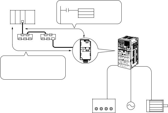
■ System Overview
Master Unit
CS1W-DRM21(-V1)
CJ1W-DRM21
C200HW-DRM21-V1 Message communications function
CVM1-DRM21-V1
CMND(490) |
Reading Inverter output |
|
current |
3G3MV, 3G3RV, 3G3PV, or 3G3FV Inverter
Remote I/O function
Output (PLC to Inverter)
|
|
|
Bit 7 |
Bit 6 |
|
Bit 5 |
Bit 4 |
Bit 3 |
Bit 2 |
|
Bit 1 |
Bit 0 |
|
Right- |
0 |
|
Net.Ref. |
Net.Ctrl. |
|
|
Reset |
|
Reverse/ |
Forward/ |
|
n |
most |
|
|
|
|
Stop |
Stop |
|||||
|
Left- |
1 |
|
|
|
|
|
|
|
|
|
|
|
most |
|
|
|
|
|
|
|
|
|
|
|
n+1 |
Right- |
2 |
|
|
|
Rotational |
speed reference rightmost bytes |
|
||||
most |
|
|
|
|
|
|
|
|
|
|
|
|
|
Left- |
3 |
|
|
Rotational speed reference leftmost bytes |
|
|
|||||
|
most |
|
|
|
|
|||||||
Input (Inverter to PLC)
3G3MV-PDRT2 DeviceNet Communications Unit
(For 3G3MV Inverters) 3G3RV-PDRT2
DeviceNet Communications Card
(For 3G3RV, 3G3PV, and 3G3FV Inverters)
Note: T-branch wiring using |
|
|
Thin Cables |
Power |
|
Switch |
|
|
supply |
Motor |
Run Reverse
Forward Stop
Selection of either the communications control input or local control input is possible using Net.Ctrl./Net.Ref.
1-4

Functions and System Configuration |
Chapter 1 |
1-2 Overview of Smart Slave Functions
As a Smart Slave, the DeviceNet Communications Unit/Card (3G3MV-PDRT2 or 3G3RV-PDRT2) is equipped with new Smart Slave functions. This chapter introduces the Smart Slave functions. Refer to 7-2 Smart Slave Functions for more details and setting/monitoring procedures.
■ Average Power Monitor Function
This function monitors the power that the Inverter supplies each hour and determines the cumulative power usage from the hourly average. The amount of power used by the system can be obtained without using special sensors or performing any calculations. In addition, monitoring the power usage can help reduce energy usage and identify power consumption problems in the system.
The average power can be easily monitored from a Configurator, Programmable Terminal (NS Series), or other operator interface.
■ Warning Torque Detection Function
This function can detect equipment errors by monitoring the output current.
Problems in the load can be detected in the Inverter’s current (torque) level. The function provides advanced warning of an increased load caused by deterioration in the mechanical system (such as a loose chain, low bearing oil, or worn-out equipment), so preventative maintenance can be performed.
Note This function generates a warning (alarm), so operation will continue.
■ Current Trace Function
This function traces (samples and records) the output current waveform to the motor. Troubleshooting can be performed easily, without connecting measuring equipment. The Configurator can be used to set the current trace’s trigger setting, set the sampling cycle, and display the current waveform.
■ Operating Time Monitor Function
This function can perform a high-speed calculation in the Slave (independent of the ladder program) to determine the time required for an input to go ON after a particular signal or reference goes ON. The Slave can report (through the Unit status flags) when the operating time exceeds the SV set in the Slave.
■ Cumulative ON Time Monitor Function
This function totals the time that one of the Inverter’s control I/O terminals is ON. For example, if the RUN output’s ON time is totaled, it is possible to calculate the Inverter’s operating time and monitor equipment operating time without using the ladder program.
1-5
Functions and System Configuration |
Chapter 1 |
Note The input from the Inverter’s control terminal block is ORed with the input from DeviceNet communications, so the input is considered ON when either input source is ON. For example, when either the RUN/STOP signal is input from the control terminal block or the input is being received from DeviceNet communications, the corresponding multi-function input terminal is considered as ON and the ON time is added.
■ Contact Operations Monitor Function
This function counts the number of times that one of the Inverter’s control I/O terminals goes ON/ OFF. The number of ON/OFF operations can be useful in maintenance, e.g., it can indicate when a connected device needs to be replaced.
Note The input from the Inverter’s control terminal block is ORed with the input from DeviceNet communications, just as it is in the Cumulative ON Time Monitor Function.
■ Conduction Time Monitor Function
Totals and records the time that power is supplied to the Slave’s internal circuit power supply. The Slave can report (through the Unit status flags) when the cumulative ON time reaches the SV set in the Slave. The DeviceNet Communications Unit/Card has three set values that can be set independently for the following three time monitoring functions.
•Main Unit operating time
•Fan operating time
•Electrolytic capacitor operating time
Since the fan operating time and electrolytic capacitor operating time are used to indicate when those parts need to be replaced, these monitoring times can be reset to zero (with an operation in the Configurator’s Device Monitor Window).
■ Baud Rate Auto-detection
In earlier Slaves it was necessary to set the baud rate with a DIP switch on the Slave, but it isn’t necessary to set the baud rate for Smart Slaves. The baud rate is automatically set to match the Master’s baud rate.
■ Network Power Supply Voltage Monitor Function
The network power supply values (present value, maximum value, and minimum value) can be recorded in the Slave. In addition, the Slave can report (through the Unit status flags) when the voltage drops below the SV (monitor voltage) set in the Slave.
■ Unit Comment Function
An user-defined name can be set for each Unit and the names can be stored in the Slaves.
■ Connected Device Comment Function
User-defined names can be set for the motor connected to the Inverter and devices connected to control I/O terminals, and those names can be stored in the Inverter.
1-6
Functions and System Configuration |
Chapter 1 |
■ Communications Error Log Monitor Function
The error status (communications error source code and communications power supply voltage at the time) for the last four communications errors can be recorded in the Slave.
■ Last Maintenance Date (Maintenance Function)
The date of the last maintenance can be written in the Unit.
■ Parameter Setting Function
The Inverter’s user parameters can be set with the Configurator. There are two ways to set the parameters, as follows:
•Several of the major parameters can be displayed and set.
•An individual parameter’s Instance/Attribute can be specified and set.
1-7

Functions and System Configuration |
Chapter 1 |
|
|
|
|
1-3 Comparison to Earlier Models
The following table shows the functions that have been added to the DeviceNet Communications Unit/Card (3G3MV-PDRT2 and 3G3RV-PDRT2), which are not available in the earlier DeviceNet Communications Unit/Card (3G3MV-PDRT1-SIN@ and 3G3FV-PDRT1-SIN@).
Refer to the Chapter in the “Reference” column for more details on each function.
■ Function Comparison Table
Category |
Function |
New Unit/Card |
Earlier Unit/Card |
Reference |
|
|
|
|
(@-PDRT2) |
(@-PDRT1-SIN@) |
|
Remote I/O |
I/O allocation |
Basic I/O |
Supported |
Supported |
Chapter 5 |
|
|
|
|
|
|
|
|
Standard I/O |
Supported |
Supported |
|
|
|
|
|
|
|
|
|
Advanced I/O |
Supported |
Supported |
|
|
|
|
|
|
|
|
|
Control I/O |
Supported |
Supported |
|
|
|
|
(Advanced Func- |
|
|
|
|
|
tion) |
|
|
|
|
|
|
|
|
|
|
Unit Status |
Supported |
Not supported |
|
|
|
|
(Advanced Func- |
|
|
|
|
|
tion) |
|
|
|
|
|
|
|
|
|
|
Multi-function |
Supported |
Not supported |
|
|
|
Input Monitor |
(Advanced Func- |
|
|
|
|
|
tion) |
|
|
|
|
|
|
|
|
DeviceNet |
Connection type |
Poll |
Supported |
Supported |
Chapter 5 |
Master con- |
|
|
|
|
|
|
Bit strobe |
Supported |
Not supported |
|
|
nectivity |
|
|
|||
|
|
|
|
|
|
|
Change of state |
Supported |
Not supported |
|
|
|
|
|
|||
|
|
|
(Advanced Func- |
|
|
|
|
|
tion) |
|
|
|
|
|
|
|
|
|
|
Cyclic |
Supported |
Not supported |
|
|
|
|
|
|
|
|
Connection path switching |
Supported |
Supported |
|
|
|
(Selecting I/O allocation in Master’s |
|
|
|
|
|
parameters) |
|
|
|
|
|
|
|
|
|
|
|
Default connection path switching |
Supported |
Supported |
|
|
|
(Selecting the I/O allocation in the |
(Advanced Func- |
|
|
|
|
Slave when power goes ON) |
tion) |
|
|
|
|
|
|
|
|
|
|
Baud rate auto-detect |
Supported |
Not supported |
Chapter 7 |
|
|
(Baud rate set automatically.) |
|
|
|
|
|
|
|
|
|
|
Inverter |
Parameter settings |
|
Supported |
Supported |
See note. |
|
|
|
(Advanced Func- |
|
|
|
|
|
tion) |
|
|
1-8
Functions and System Configuration |
|
Chapter 1 |
||
|
|
|
|
|
Category |
Function |
New Unit/Card |
Earlier Unit/Card |
Reference |
|
|
(@-PDRT2) |
(@-PDRT1-SIN@) |
|
Smart Slave |
Average Power Monitor Function |
Supported |
Not supported |
Chapter 7 |
functions |
|
(Advanced Func- |
|
|
|
|
tion) |
|
|
|
|
|
|
|
|
Warning Torque Detection Function |
Supported |
Not supported |
|
|
|
(Advanced Func- |
|
|
|
|
tion) |
|
|
|
|
|
|
|
|
Current Trace Function |
Supported |
Not supported |
|
|
|
(Advanced Func- |
|
|
|
|
tion) |
|
|
|
|
|
|
|
|
Operating Time Monitor Function |
Supported |
Not supported |
|
|
|
(Advanced Func- |
|
|
|
|
tion) |
|
|
|
|
|
|
|
|
Cumulative ON Time Monitor Function |
Supported |
Not supported |
|
|
|
(Advanced Func- |
|
|
|
|
tion) |
|
|
|
|
|
|
|
|
Contact Operations Monitor Function |
Supported |
Not supported |
|
|
|
(Advanced Func- |
|
|
|
|
tion) |
|
|
|
|
|
|
|
|
Conduction Time Monitor Function |
Supported |
Not supported |
|
|
|
(Advanced Func- |
|
|
|
|
tion) |
|
|
|
|
|
|
|
|
Network Power Supply Voltage Monitor |
Supported |
Not supported |
|
|
Function |
|
|
|
|
|
|
|
|
|
Unit Comment Function |
Supported |
Not supported |
|
|
|
|
|
|
|
Connected Device Comment Function |
Supported |
Not supported |
|
|
|
|
|
|
|
Communications Error Log Monitor |
Supported |
Not supported |
|
|
Function |
|
|
|
|
|
|
|
|
|
Last Maintenance Date (Maintenance |
Supported |
Not supported |
|
|
Function) |
|
|
|
|
|
|
|
|
Note Refer to 7-3 Edit Device Parameters Window for details on setting parameters with the Configurator.
refer to 5-5 Special Remote I/O Operation for details on setting parameters with special remote I/O.
Refer to 6-7 Reading and Writing Parameters: Class 64 Hex for details on setting parameters with message communications.
Refer to Chapter 10 Appendices for reference data such as register numbers, which are required when setting parameters. The information is organized by Inverter series.
■ Comparison of Installation Specifications
The installation conditions for the 3G3MV-PDRT2 have changed in comparison to those for the 3G3MV-PDRT1-SINV(1). Observe the following precautions when changing models.
• Install the Unit into a metal panel.
The EMC immunity of the 3G3MV-PDRT2 is somewhat less than that of the 3G3MV-PDRT1- SINV(1). Refer to 3-4 Conformity to EC Directives for information on electromagnetic wave countermeasures.
• The installation dimension at the bottom has been increased by 7 mm.
1-9
Functions and System Configuration |
Chapter 1 |
The 3G3MV-PDRT2 is equipped with a connector for DeviceNet connection rather than a terminal block. The dimension of the connector that extends below the case must be added.
■ Inverter Software Versions
Supported software versions are listed in the following table.
Model |
Software version |
Release date |
Description |
|
|
|
|
|
|
3G3MV Series, |
VSP010027 (S0027) |
June 2003 |
Supports all functions. |
|
3.7 kW and less |
and higher |
|
Current trace function and warning torque |
|
|
|
|
detection function use increments of 0.01 A. |
|
|
|
|
|
|
|
VSP010026 (S0026) |
June 2002 |
Supports all functions. |
|
|
|
|
Current trace function and warning torque |
|
|
VSP010025 (S0025) |
June 2001 |
||
|
|
|
detection function are use increments of |
|
|
VSP010024 (S0024) |
September 2000 |
||
|
0.1 A for detection and display. |
|||
|
|
|
||
|
|
|
|
|
3G3MV Series, |
VSP010105 (S0105) |
September 2002 |
Supports all functions. |
|
5.5 kW and more |
|
|
Current trace function and warning torque |
|
VSP010104 (S0104) |
May 2001 |
|||
|
||||
|
|
|
detection function are use increments of |
|
|
|
|
0.1 A for detection and display. |
|
|
|
|
|
|
3G3RV Series |
VSF105081 (S5081) |
November 2001 |
Supports all functions. |
|
|
and higher |
|
Current trace function and warning torque |
|
|
|
|
detection function are use increments of |
|
|
|
|
0.1 A for detection and display. |
|
|
|
|
|
|
3G3PV Series |
VSE102014 (S2014) |
July 2002 |
Supports all functions. |
|
|
|
|
Current trace function and warning torque |
|
|
VSE102013 (S2013) |
March 2001 |
||
|
|
|
detection function are use increments of |
|
|
|
|
0.1 A for detection and display. |
|
|
|
|
|
|
3G3FV Series |
VSG101114 (S1114) |
September 2002 |
It is not possible to force-switch the com- |
|
|
|
|
mand right from the network. Specifically, |
|
|
VSG101113 (S1113) |
September 2000 |
||
|
even if netref and netctrl (see Chapter 5 |
|||
|
|
|
||
|
VSG101043 (S1043) |
September 1998 |
||
|
Remote I/O Functions) are turned ON, the |
|||
|
|
|
||
|
|
|
command right will not be switched to the |
|
|
|
|
network. Use parameters b1-02 and b1-01 |
|
|
|
|
to set the command right. |
|
|
|
|
There are no restrictions to other functions. |
|
|
|
|
|
1-10
Functions and System Configuration |
Chapter 1 |
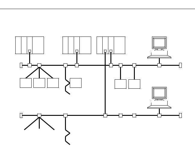
1-4 DeviceNet Features
■ System Configuration Example
|
Master by other |
|
|
OMRON Master Unit |
company |
OMRON Master Unit |
OMRON Configurator |
DeviceNet Network
OMRON Configurator
OMRON Slaves |
|
OMRON Slaves |
|
|
|
|
|
|
|
|
|
|
|
|
|
Slaves by other company
DeviceNet Network
|
|
|
|
|
|
|
|
|
|
|
|
|
|
|
|
|
|
|
|
|
|
|
|
|
|
|
|
|
|
|
|
|
|
|
|
|
|
|
|
|
|
|
|
|
|
|
|
|
|
|
|
|
|
|
|
|
|
|
|
|
|
|
|
|
|
|
|
|
|
|
|
|
|
|
|
|
|
|
|
|
|
|
|
|
|
|
|
|
|
|
|
|
|
|
|
|
|
|
|
|
|
|
|
Slaves by other company |
|
|
|
Slaves by other company |
|
||||||||||||||||||||
|
|
|
|
||||||||||||||||||||||
|
|
|
|
|
|
|
|
|
|
|
|
|
|
|
|
|
|
|
|
|
|
|
|
|
|
OMRON Slaves
■ Multi-vendor Network
The DeviceNet conforms to the DeviceNet open field network specification, which means that devices (Masters and Slaves) produced by other manufacturers can also be connected to the Network. Therefore, a wide range of field-level applications can be supported by combining valve devices, sensors, and other devices.
■ Simultaneous Remote I/O and Message Services
Remote I/O communications to constantly exchange I/O data between the PLC and Slaves can be executed simultaneously with message communications, to send/receive DeviceNet (Master) Unit data as required by the application. Therefore, a DeviceNet Network can be installed to flexibly handle applications that require both bit data and message data. Message communications can be achieved either by using OMRON's FINS commands or by using DeviceNet explicit messages.
1-11
Functions and System Configuration |
Chapter 1 |
■ Connect Multiple PLCs to the Same Network
A Configurator (sold separately) can be used to enable connection of more than one Master to the Network, allowing message communications between PLCs and between multiple groups of PLCs and Slaves. This allows the DeviceNet Network to be used as a common bus to unify controls while reducing wiring.
■Handle Multi-point Control and Line Expansions with Multi-layer Networks
A Configurator (sold separately) can be used to enable mounting more than one DeviceNet (Master) Unit to a single PLC, allowing control of many more points. This feature can easily handle line expansions and other applications.
■ Free Remote I/O Allocation
A Configurator (sold separately) can be used to enable flexible allocation of I/O, i.e., in any area and in any order. This allows I/O allocations that suit the application to simplify programming and enable effective usage of PLC memory areas.
■ Handle Slaves with Different Response Speeds
A Configurator (sold separately) can be used to set the communications cycle time, enabling usage of Slaves with slow response times.
■ Easily Expand or Change Lines with Various Connection Methods
Use a multi-drop trunk line, T-branch multi-drop lines, or daisy-chain drop lines. All three connection methods can be combined to flexibly construct a Network that meets the needs of the application.
Note For connecting the DeviceNet Communications Unit of the Inverter, use DCA1-5C10 Thin Cables and branch them from the T-branch Tap.
1-12
Functions and System Configuration |
Chapter 1 |
1-5 DeviceNet System Configuration
1-5-1 System Configuration
DeviceNet is a multi-bit, multi-vendor network that combines controls and data on a machine/linecontrol level and that conforms to DeviceNet open field network specifications.
Two types of communications are supported: 1) Remote I/O communications that automatically transfer I/O between Slaves and the CPU Unit of a PLC without any special programming in the CPU Unit and 2) Message communications are performed between a CPU Unit to which a DeviceNet (Master) Unit is mounted and Slaves by executing specific instructions (such as CMND and IOWR, depending on the model of PLC used) from the program in the CPU Unit.
A Configurator (sold separately) can be used to enable following. This allows the support of an even larger control system.
•I/O area words can be flexibly allocated for remote I/O communications.
•More than one DeviceNet (Master) Unit can be mounted to a single PLC.
•More than one DeviceNet (Master) Unit can be connected in a single Network.
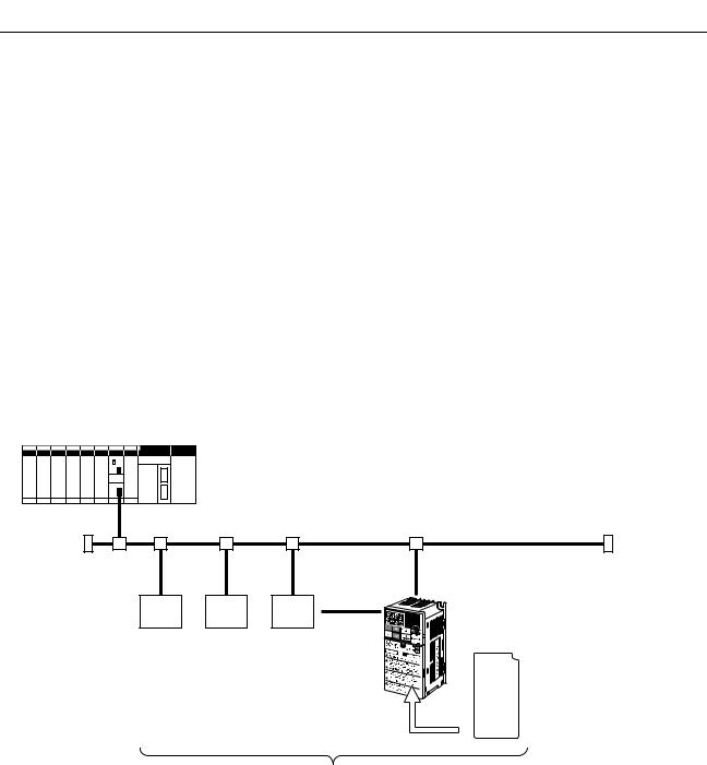
■Fixed Allocation: Configuration without a Configurator
DeviceNet Master Unit
CS1W-DRM21(-V1)
CJ1W-DRM21
C200HW-DRM21-V1
CVM1-DRM21-V1
|
|
|
SYSDRIVE 3G3MV, |
|
|
|
|
3G3RV, 3G3PV, or |
|
Slave |
Slave |
Slave |
3G3FV Inverter |
|
3G3MV-PDRT2 |
||||
|
|
|
||
|
|
|
DeviceNet Communications |
|
|
|
|
Unit (For 3G3MV Inverters) |
|
|
|
|
3G3RV-PDRT2 |
|
|
|
|
DeviceNet Communications |
|
|
|
|
Card |
|
|
|
|
(For 3G3RV, 3G3PV, and |
|
|
|
|
3G3FV Inverters) |
CS/CJ-series PLCs: |
64 nodes max. (including the Master Unit) |
CV-series PLCs: |
64 nodes max. (including the Master Unit) |
C200HX/HG/HE PLCs: 51 nodes max. (including the Master Unit) |
|
C200HS PLCs: |
33 nodes max. (including the Master Unit) |
Note |
1. |
The DeviceNet (Master) Unit occupies one node of the DeviceNet Network. |
Note |
2. |
If C200HS PLCs are used, only remote I/O communications are possible. |
Note |
3. |
If one node uses more than one word, the maximum number of nodes will be reduced by |
|
|
one node for each extra word that is used. (The above numbers of nodes assume that each |
|
|
node is allocated one I/O word.) |
1-13
Functions and System Configuration |
Chapter 1 |
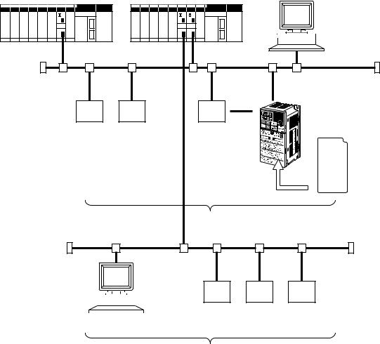
■ Free Allocation: Configuration with a Configurator
DeviceNet Master Unit
CS1W-DRM21(-V1)
CJ1W-DRM21
C200HW-DRM21-V1
CVM1-DRM21-V1
3G8F5-DRM21-E (ISA Board) or SG8E2-DRM21-EV1 (PC Card) Configurator
|
|
SYSDRIVE 3G3MV, |
|
|
3G3RV, 3G3PV, or |
Slave |
Slave |
3G3FV Inverter |
Slave |
3G3MV-PDRT2
DeviceNet Communications
Unit
(For 3G3MV Inverters)
3G3RV-PDRT2
DeviceNet Communications
Card (For 3G3RV, 3G3PV,
and 3G3FV Inverters)
64 nodes max. (including the Master Unit)
|
|
|
|
|
|
|
|
|
|
|
|
|
|
|
|
|
|
|
|
|
|
|
|
|
|
|
|
|
|
|
|
|
|
|
|
|
|
|
|
|
|
|
|
|
|
|
|
|
|
|
|
|
|
|
|
|
|
|
|
|
|
|
|
|
|
|
|
|
|
|
|
|
|
|
|
|
|
|
|
|
|
|
|
|
|
|
|
|
|
|
|
|
|
|
|
|
|
|
|
|
|
|
|
|
|
|
|
|
|
|
|
|
|
|
|
|
|
|
|
|
|
|
|
|
|
|
|
|
|
|
|
|
|
|
|
|
|
|
|
|
|
|
|
|
|
|
|
|
|
|
|
|
|
|
|
|
|
|
|
|
|
|
|
|
|
|
|
|
|
|
|
|
|
|
|
|
|
|
|
|
|
|
|
|
|
|
|
|
|
|
|
|
|
|
|
|
|
|
|
|
|
|
|
Slave |
|
Slave |
Slave |
||||||||
|
|
|
|
|
|
|
|
|
|
|
|
|
|
|
|
|||||||||||
|
|
|
|
|
|
|
|
|
|
|
|
|
|
|
|
|||||||||||
|
|
|
|
|
|
|
|
|
|
|
|
|
|
|
|
|||||||||||
|
|
|
Configurator |
|
|
|
|
|
|
|
|
|
||||||||||||||
|
|
|
|
|
|
|
|
64 nodes max. (including the Master Unit) |
||||||||||||||||||
Note |
1. |
The DeviceNet (Master) Unit and Configurator each occupy one node of the DeviceNet Net- |
||||||||||||||||||||||||
|
|
work. |
|
|
|
|
|
|
|
|
|
|||||||||||||||
Note |
2. |
If C200HS PLCs are used, only remote I/O communications are possible. |
||||||||||||||||||||||||
Note |
3. |
The maximum number of nodes that can be connected to the Network will be limited by the |
||||||||||||||||||||||||
|
|
maximum number of control points of the PLC used. |
|
|
|
|
||||||||||||||||||||
1-14
Functions and System Configuration |
Chapter 1 |
1-5-2 Configurator Overview
The Configurator is a software application run on an IBM PC/AT or compatible computer and is used to support a DeviceNet communications system. Connection to the Network is achieved either via a serial communications port (peripheral bus or Host Link) or by connecting the computer directly to the DeviceNet using a hardware interface. The Configurator occupies one node on the DeviceNet Network, but has no specific functions on the network itself. The Configurator provides the following functions.
•Free Allocation of Remote I/O
The remote I/O allocations in the PLCs can be changed from the Configurator. I/O can be flexibly allocated for each node within the specified I/O areas.
•More than One DeviceNet (Master) Unit per Network
Slaves can be set for each DeviceNet (Master) Unit from the Configurator enabling communications between multiple groups of PLCs and Slaves. The maximum number of nodes connected to one Network remains at 64.
Note One Slave can be connected to no more than one DeviceNet (Master) Unit.
•More than one DeviceNet (Master) Unit per PLC
Remote I/O can be allocated for each Slave of the DeviceNet (Master) Unit from the Configurator, so more than one DeviceNet (Master) Unit can be mounted to the same PLC.
Note In allocating Remote I/O for each DeviceNet (Master) Unit, be careful not to allow any dual allocation.
■ Configurator Specifications
Dedicated interface |
--- |
3G8F5-DRM21-E |
3G8E2-DRM21-EV1 |
|
|
|
|
Software |
WS02-CFDC1-E |
Packaged with the Interface |
|
|
|
|
|
Personal computer |
Desktop model or |
Desktop model (ISA |
Notebook model |
|
Notebook model |
Board) |
(PCMCIA Card) |
|
|
|
|
1-15

|
Functions and System Configuration |
Chapter 1 |
||||
|
|
|
|
|
|
|
|
Dedicated interface |
--- |
3G8F5-DRM21-E |
3G8E2-DRM21-EV1 |
||
|
|
|
|
|
|
|
|
Operating |
Compatible |
Windows 95, 98, ME, |
Windows 95, 98, ME, |
Windows 95, 98, 2000, |
|
|
environ- |
OS |
NT 4.0, 2000, or XP |
or NT 4.0 |
or XP |
|
|
ment |
|
|
|
|
|
|
Minimum comIBM PC/AT or compatible (OS requirements may be stricter than the fol- |
|||||
|
|
|||||
|
|
puter require- |
lowing.) |
|
|
|
|
|
ments |
CPU: 166 MHz Pentium min. |
|
|
|
|
|
|
Memory: 32 MB min. |
|
|
|
|
|
|
Hard disk: 15 MB min. free space |
|
|
|
|
|
|
|
|
|
|
|
Connec- |
Dedicated |
Sold separately |
ISA Board |
PCMCIA Card |
|
|
tion |
interface |
|
|
|
|
|
method |
|
|
|
|
|
|
Serial |
Connect from the computer’s COM port through a CS/CJ-series PLC. |
||||
|
|
|||||
|
|
|
(This connection is possible when a CS/CJ-series DeviceNet (Master) |
|||
|
|
|
Unit is being used.) |
|
|
|
|
|
|
|
|
||
|
|
Ethernet |
Connect from the computer’s Ethernet port through a CS/CJ-series |
|||
|
|
|
PLC’s Ethernet. |
|
|
|
|
|
|
(This connection is possible when a CS/CJ-series DeviceNet (Master) |
|||
|
|
|
Unit is being used.) |
|
|
|
|
|
|
|
|
|
|
|
Relation to Network |
Using a dedicated interface: Connect directly to DeviceNet. |
||||
•Operates as one node on the Network, requires one node address, and only one Configurator can be connected to the Network.
•The Configurator can be disconnected from the Network after remote I/ O has been allocated.
Using a serial or Ethernet connection:
•Possible only when a CS/CJ-series DeviceNet (Master) Unit is being used.
•A DeviceNet node address is not required. (Connects through the DeviceNet (Master) Unit.)
•A node address is not allocated, so the Configurator can be connected or disconnected freely. (There are some limitations compared to a direct DeviceNet connection through a dedicated interface. For example, the refreshing interval for PV monitoring is much slower that it is with a direct connection.)
1-5-3 DeviceNet Communications Specifications
Item |
Specifications |
|
|
Communications protocol |
DeviceNet |
|
|
Supported connections (com- |
• Remote I/O |
munications) |
Master/Slave connection (Poll, Bit-strobe, COS, or Cyclic) |
|
• Explicit messages |
|
Explicit connection |
|
Both conform to DeviceNet specifications. |
|
|
Connection forms |
Combination of multi-drop and T-branch connections (for trunk and drop |
|
lines) |
|
|
Baud rate |
500 Kbps, 250 Kbps, or 125 Kbps (switchable) |
|
|
Communications media |
Special 5-wire cables (2 signal lines, 2 power lines, and 1 shield line) |
|
• Thick Cable: DCA2-5C10 (100 m) |
|
• Thin Cable: DCA1-5C10 (100 m) |
|
|
1-16
Loading...