


LE840DT
Table of contents
 Loading...
LE840/LE850
User’s Guide
PREFACE
Every effort has been made to ensure that the information in this document is complete, accurate, and
up-to-date. The manufacturer assumes no responsibility for the results of errors beyond its control. The
manufacturer also cannot guarantee that changes in software and equipment made by other
manufacturers and referred to in this manual will not affect the applicability of the information in it.
Mention of software products manufactured by other companies does not necessarily constitute
endorsement by the manufacturer.
While all reasonable efforts have been made to make this document as accurate and helpful as possible,
we make no warranty of any kind, expressed or implied, as to the accuracy or completeness of the
information contained herein.
All rights are reserved by Oki Data Corporation. Unauthorized copying, transferring, translating, or
related actions are prohibited. You must obtain written permission from Oki Data Corporation before
doing any of the above.
© 2012 Oki Data Corporation
OKI is a registered trademark of Oki Electric Industry Co., Ltd.
Energy Star is a trademark of the United States Environmental Protection Agency.
Microsoft, Windows, Windows Server and Windows Vista are registered trademarks of Microsoft
Corporation.
Apple, Macintosh, Rosetta, Mac and Mac OS are registered trademarks of Apple Inc.
Other product names and brand names are registered trademarks or trademarks of their proprietors.
As an Energy Star Program Participant, the manufacturer has determined that this product
meets the Energy Star guidelines for energy efficiency.
This product complies with the requirements of the Council Directives 2004/108/EC (EMC) and
2006/95/EC (LVD), 1999/5/ EC (R&TTE) and 2011/65/EU(RoHS) as amended where applicable,
on the approximation of the laws of the member states relating to Electromagnetic
Compatibility, Low Voltage, Radio & Telecommunications Terminal Equipment, Energy
related Products and Restriction on the use of certain Hazardous Substances in electrical
and electronic equipment.
The following cables were used to evaluate this product to achieve EMC directive
2004/108/EC compliance and configurations other than this may affect that compliance.
CABLE TYPE CORECABLE TYPE CORECABLE TYPE LENGTH
(METRE)
Power
USB
Serial
Parallel
LAN
2.0
1.5
2.0
4.0
3.0
CORE SHIELD
WARNING! This is a class A product as defined in EN55022. In a domestic environment
this product may cause radio interference, in which case the user may be required to
take adequate measures.
- 2 -

M
ANUFACTURER
Oki Data Corporation,
4-11-22 Shibaura, Minato-ku,
Tokyo 108-8551,
Japan
For all sales, support and general enquiries contact your local distributor.
I
MPORTER TO THE
OKI Europe Limited (trading as OKI Printing Solutions)
Blays House
Wick Road
Egham
Surrey, TW20 0HJ
United Kingdom
For all sales, support and general enquiries contact your local distributor.
E
NVIRONMENTAL INFORMATION
EU/A
UTHORISED REPRESENTATIVE
-3-

CE Compliance (for EU only)
This product complies with the requirements of EMC and Low Voltage Directives including their
amendments.
VORSICHT:
• Schallemission: unter 70dB (A) nach DIN 45635 (oder ISO 7779)
•
Die für das Gerät Vorgesehene Steckdose muß in der Nähe des Gerätes und leicht zugänglich sein.
Centronics is a registered trademark of Centronics Data Computer Corp.
Microsoft is a registered trademark of Microsoft Corporation.
Windows is a trademark of Microsoft Corporation.
This equipment has been tested and found to comply with the limits for a Class A digital device,
pursuant to Part 15 of the FCC Rules. These limits are designed to provide reasonable protection
against harmful interference when the equipment is operated in a commercial environment. This
equipment generates, uses, and can radiate radio frequency energy and, if not installed and set in
accordance with the instruction manual, may cause harmful interference to radio communications.
Operations of this equipment in a residential area is likely to cause harmful interference in which case
the user will be required to correct the interference at his own expense.
Changes or modifications not expressly approved by the manufacturer for compliance could void the
user’s authority to operate the equipment.
“This Class A digital apparatus meets all requirements of the Canadian Interference-Causing
Equipment Regulations.”
“Cet appareil numérique de la classe A respecte toutes les exigences du Règlement sur le matériel
brouilleur du Canada.”
(for USA only)
(for CANADA only)

Precautions for the handling of Wireless Communication Devices
Wireless LAN Module: SD-Link 11g
For Europe
This device was tested and certified by Notified Body.
Hereby, Oki Data Corporation declares that this device is in compliance with the essential requirements and
other relevant provisions of Directive 1999/5/EC.
This equipment uses the radio frequency band which has not been standardised throughout the EU and EFTA
countries. It can be used in the following countries.
Austria, Belgium, Bulgaria, Cyprus, Czech Republic, Denmark, Estonia, Finland, France, Hungary, Germany,
Greece, Ireland, Italy, Latvia, Lithuania, Luxembourg, Malta, Netherlands, Poland, Portugal, Romania, Slovakia,
Slovenia, Spain, Sweden, United Kingdom, Norway, Liechtenstein, Iceland, Switzerland
For USA
This device complies with Part 15 of the FCC Rules.
Operation is subject to the following two conditions:
(1) This device may not cause harmful interference, and
(2) This device must accept any interference r eceived, including interference that may cause undesired
operation.
Changes or modification not expressly approved by manufacturer for compliance could void the user’s authority
to operate the equipment.
For Canada
Operation is subject to the following two conditions:
(1) This device may not cause interference, and
(2) This device must accept any interference, including interference that may cause undesired operation of the
device.
For safety
Do not operate this product in locations where its use may be prohibited. For example, in an aeroplane or
hospital. If you are unsure whether operation is permitted, please refer to and follow the airline company or
medical institution guidelines.
Otherwise, flight instrument or medical equipment may be affected, causing a serious accident.
This product may affect the operation of some implanted cardiac pacemakers and other medically implanted
equipment. Pacemaker patients should be aware that the use of this product in close proximity to a pacemaker
might cause the device to malfunction.
If you have any reason to suspect that interference is taking place, immediately turn off the product and contact
your Oki Data sales agent.
Do not disassemble, modify, or repair the product as doing so may cause injury.
Modification is also against the Laws and Regulations for Radio Equipment. Please ask your Oki Data sales
agent for repair.
Safety Summary
WARNING
Use only
specified
Prohibited
Prohibited
Prohibited
Prohibited
Prohibited
Disconnect
Disconnect
Safety Summary
Personal safety in handling or maintaining the equipment is extremely important. Warnings and Cautions
necessary for safe handling are included in this manual. All warnings and cautions contained in this manual
should be read and understood before handling or maintaining the equipment.
Do not attempt to effect repairs or modifications to this equipment. If a fault occurs that cannot be rectified
using the procedures described in this manual, turn off the power, unplug the machine, and then contact your
authorised
Oki Data
representative for assistance.
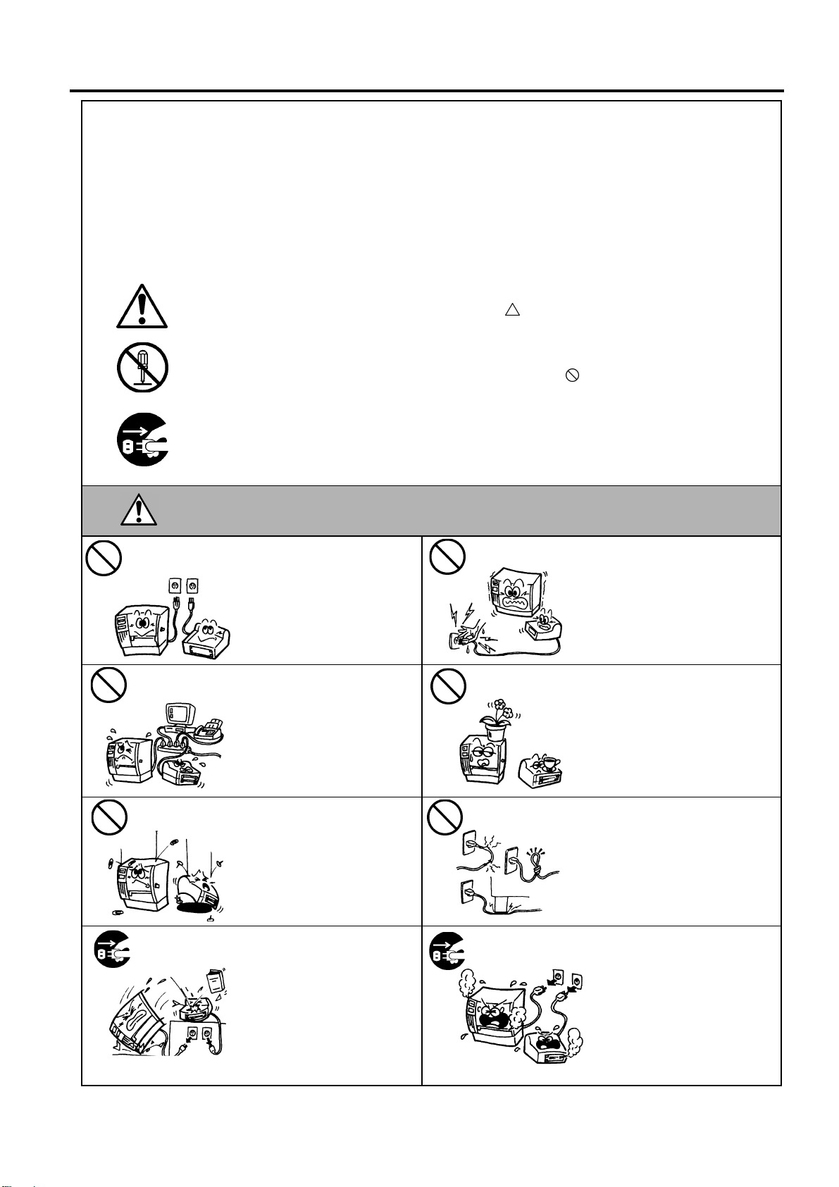
Meanings of Each Symbol
This symbol indicates warning items (including cautions).
Specific warning contents are drawn inside the symbol.
(The symbol on the left indicates a general caution.)
This symbol indicates prohibited actions (prohibited items).
Specific prohibited contents are drawn inside or near the symbol.
(The symbol on the left indicates “no disassembling”.)
This symbol indicates actions which must be performed.
Specific instructions are drawn inside or near the symbol.
(The symbol on the left indicates “disconnect the power cord plug from the outlet”.)
AC voltage.
This indicates that there is the risk of death or serious injury if the
machine is improperly handled contrary to this indication.
Do not use voltages other than
the AC voltage specified on the
rating plate, as this may cause
fire or electric shock.
If the machine shares the same
electrical outlet, with any other
appliance that consumes a large
amount of power, the voltage will
fluctuate widely each time these
appliances operate. Be sure to
provide an exclusive outlet for
the machine as this may cause
fire or electric shock.
Do not insert or drop metal,
flammable or other foreign
objects into the machine through
ventilation slits, as this may
cause fire or electric shock.
Do not plug in or unplug the power
cord with wet hands as this may
cause electric shock.
Do not place metal objects or
water-filled containers (flower
vases, flower pots or mugs etc) on
top of the machine. If metal
objects or spilled liquids enter the
machine, this may cause fire or
electric shock.
Do not scratch, damage or modify
the power cords. Do not place
heavy objects on, pull on, or
excessively bend the power cords,
as this may cause fire or electrical
shock.
the plug.
If the machine is dropped or the
cabinet is damaged, turn off the
power switch and disconnect the
power cord plug from the outlet,
and then contact your authorised
Oki Data representative for
assistance. Continued use of a
damaged machine may cause fire
or electric shock.
( )
i
the plug.
Continued use of the machine in an
abnormal condition (the machine is
producing smoke or a strange
smell) may cause fire or electric
shock. In these cases, immediately
turn off the power switch and
disconnect the power cord plug
from the outlet. Then, contact your
authorised Oki Data representative
for assistance.
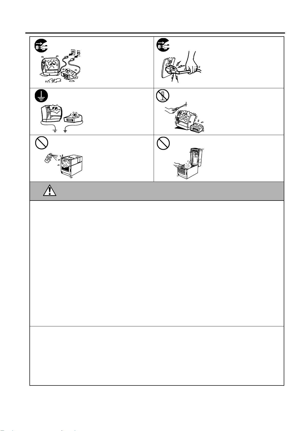
Safety Summary
CAUTION
Disconnect
Disconnect
Connect a
No
Prohibited
Prohibited
the plug.
grounding wire.
If foreign objects (metal
fragments, water, liquids) enter
the machine, turn off the power
switch and disconnect the power
cord plug from the outlet, and
then contact your authorised Oki
Data representative for assistance.
Continued use of the machine in
that condition may cause fire or
electric shock.
Ensure that the equipment is
properly grounded. Extension
cables should also be grounded.
Fire or electric shock could
occur on improperly grounded
equipment.
Do not use a spray cleaner
containing flammable gas for
cleaning this product, as this may
cause a fire.
the plug.
disassembling.
When unplugging the power cords,
be sure to hold and pull on the plug.
Pulling on the cord may cut or
expose the internal wires and cause
fire or electric shock.
Do not remove covers, repair or
modify the machine yourself.
Contact your Oki Data
representative for assistance. You
may be injured by high voltage,
very hot parts or sharp edges inside
the machine.
Care must be taken not to injure
yourself with the printer paper
cutter, projection and the edge of
sheet metal.
This indicates that there is the risk of personal Injury or damage to
objects if the machine is improperly handled contrary to this indication.
Precautions
The following precautions will help to ensure that this machine will continue to function correctly.
• Try to avoid locations that have the following adverse conditions:
* Temperatures out of the specification * Direct sunlight * High humidity
* Shared power source * Excessive vibration * Dust/Gas
• The cover should be cleaned by wiping with a dry cloth or a cloth slightly dampened with a mild detergent solution. NEVER
USE THINNER OR ANY OTHER VOLATILE SOLVENT on the plastic covers.
• USE ONLY Oki Data SPECIFIED paper and ribbons.
• DO NOT STORE the paper or ribbons where they might be exposed to direct sunlight, high temperatures, high humidity, dust,
or gas.
• Ensure the printer is operated on a level surface.
• Any data stored in the memory of the printer could be lost during a printer fault.
• Try to avoid using this equipment on the same power supply as high voltage equipment or equipment likely to cause mains
interference.
• Unplug the machine whenever you are working inside it or cleaning it.
• Keep your work environment static free.
• Do not place heavy objects on top of the machine, as these items may become unbalanced and fall causing injury.
• Do not block the ventilation slits of the machine, as this will cause heat to build up inside the machine and may cause fire.
• Do not lean against the machine. It may fall on you and could cause injury.
• Unplug the machine when it is not used for a long period of time.
• Place the machine on a stable and level surface.
•
Do not turn on the printer power while the ON LINE and ERROR lamp are blinking as this may cause damage to the printer.
• RISK OF EXPLOSION IF BATTERY IS REPLACED BY AN INCORRECT TYPE.
DISPOSE OF USED BATTERIES ACCORDING TO THE INSTRUCTIONS.
Request Regarding Maintenance
• Utilise our maintenance services.
After purchasing the machine, contact your authorised Oki Data representative for assistance once a year to have the inside of
the machine cleaned. Dust will build up inside the machines and may cause a fire or a malfunction. Cleaning is particularly
effective before humid rainy seasons.
• Our preventive maintenance service performs periodic checks and other work required to maintain the quality and performance
of the machine.
For details, please consult your authorised Oki Data representative.
• Do not expose the machine to insecticides or other volatile solvents. This may cause the cabinet, or other parts, to deteriorate
and may cause the paint to peel.
( )
ii

TABLE OF CONTENTS
Page
1. PRODUCT OVERVIEW......................................................................................................... E1- 1
1.1 Introduction................................................................................................................... E1- 1
1.2 Features ....................................................................................................................... E1- 1
1.3 Unpacking..................................................................................................................... E1- 1
1.4 Accessories ................................................................................................................. E1- 2
1.5 Appearance .................................................................................................................. E1- 3
1.5.1 Dimensions..............................................................................................................E1- 3
1.5.2 Front View ...............................................................................................................E1- 3
1.5.3 Rear View................................................................................................................E1- 3
1.5.4 Operation Panel ......................................................................................................E1- 4
1.5.5 Interior .....................................................................................................................E1- 4
1.6 Options ......................................................................................................................... E1- 5
2. PRINTER SETUP .................................................................................................................. E2- 1
2.1 Installation .................................................................................................................... E2- 2
2.2 Connecting the Power Cord ......................................................................................... E2- 3
2.3 Loading Supplies .......................................................................................................... E2- 4
2.3.1 Loading the Media...................................................................................................E2- 5
2.3.2 Loading the Ribbon ................................................................................................E2-10
2.4 Connecting the Cables to Your Printer ........................................................................ E2-12
2.5 Turning the Printer ON/OFF ........................................................................................ E2-13
2.5.1 Turning ON the Printer ...........................................................................................E2-13
2.5.2 Turning OFF the Printer..........................................................................................E2-13
2.6 Printer Setting....... .......................................... .......................................... ................................
2.6.1 User System Mode.................................................................................................E2-15
2.6.2 Parameter Setting ..................................................................................................E2-16
2.6.3 Enabling LAN/WLAN ..............................................................................................E2-24
2.6.4 Basic Program Setting............................................................................................E2-24
2.6.5 Enabling Z-Mode ....................................................................................................E2-25
2.6.6 Automatic Calibration .............................................................................................E2-26
2.6.7 Dump Mode Setting................................................................................................E2-27
2.6.8 Logging...................................................................................................................E2-29
2.6.9 System Mode .........................................................................................................E2-30
2.6.10 Interface Setting .....................................................................................................E2-31
2.6.11 Real Time Clock (RTC) ..........................................................................................E2-38
2.6.12 Copying Data to/from USB Memory .......................................................................E2-39
2.7 Installing the Printer Drivers ........................................................................................ E2-41
2.7.1 Introduction.............................................................................................................E2-41
2.7.2 General Description................................................................................................E2-41
2.7.3 Installing the Printer Driver .....................................................................................E2-42
2.7.4 Installation under Windows XP/Server 2003/Vista/
Server 2008/7/Server2008 R2................................................................................E2-42
2.7.5 Uninstalling the Printer Driver.................................................................................E2-45
2.7.5.1 For Windows 7/Server 2008 R2...........................................................................E2-45
2.7.5.2 For Windows Vista/Server 2008 ..........................................................................E2-48
2.7.5.3 Other OS .............................................................................................................E2-48
E2-14

2.8 Print Test ..................................................................................................................... E2-49
which case the user may be required to take adequate measures.
2.9 Position and Print Tone Fine Adjustment ................................................................... E2-51
2.9.1 Fine Adjustment .....................................................................................................E2-51
2.10 Threshold Setting ........................................................................................................ E2-58
2.11 Sensor Setting............................................................................................................. E2-61
3. ONLINE MODE...................................................................................................................... E3- 1
3.1 Key Functions............................................................................................................... E3- 1
3.2 LCD .............................................................................................................................. E3- 2
3.2 Operation Example....................................................................................................... E3- 3
4. MAINTENANCE .................................................................................................................... E4- 1
4.1 Cleaning ....................................................................................................................... E4- 1
4.1.1 Print Head/Platen/Sensors ......................................................................................E4- 1
4.1.2 Covers and Panels ..................................................................................................E4- 2
4.1.3 Optional Cutter Module............................................................................................E4- 3
5. TROUBLESHOOTING .......................................................................................................... E5- 1
5.1 Error Messages ............................................................................................................ E5- 1
5.2 Possible Problems........................................................................................................ E5- 4
5.3 Removing Jammed Media............................................................................................ E5- 5
6. PRINTER SPECIFICATIONS ................................................................................................ E6- 1
7. SUPPLY SPECIFICATIONS ................................................................................................. E7- 1
7.1 Media............................................................................................................................ E7- 1
7.1.1 Media Type..............................................................................................................E7- 1
7.1.2 Detection Area of the Transmissive Sensor (Gap sensor).......................................E7- 3
7.1.3 Detection Area of the Reflective Sensor (Black mark sensor).................................E7- 4
7.1.4 Effective Print Area..................................................................................................E7- 5
7.1.5 RFID Tags...............................................................................................................E7- 6
7.2 Ribbon .......................................................................................................................... E7- 8
7.3 Recommended Media and Ribbon Types .................................................................. E7- 10
7.4 Care/Handling of Media and Ribbon .......................................................................... E7- 16
APPENDIX 1 MESSAGES AND LEDS......................................................................................EA1-1
APPENDIX 2 INTERFACE.........................................................................................................EA2-1
APPENDIX 3 PRINT SAMPLES ................................................................................................EA3-1
APPENDIX 4 GLOSSARIES......................................................................................................EA4-1
WARNING!
This is a Class A product. In a domestic environment this product may cause radio interference in
CAUTION!
1. This manual may not be copied in whole or in part without prior written permission of Oki Data.
2. The contents of this manual may be changed without notification.
3. Please refer to your local Authorised Service representative with regard to any queries you may have in
this manual.
1. PRODUCT OVERVIEW
1. PRODUCT OVERVIEW
1.1 Introduction
1.2 Features
1.3 Unpacking
1. Check for damage or
scratches on the printer.
However, please note that
Oki Data shall have no
liability for any damage of
any kind sustained during
transportation of the product.
2. Keep the cartons and internal
packing for future
transportation of the printer.
NOTES:
Thank you for choosing the Oki Data LE840/LE850 series label printer.
This User’s Guide contains from general set-up through to how to
confirm the printer operation using a test print, and should be read
carefully to help gain maximum performance and life from your printer.
For most queries please refer to this manual and keep it safe for future
reference. Please contact your Oki Data representative for further
information concerning this manual.
This printer has the following features:
• The print head block can be opened providing smooth loading of
media and ribbon.
• Various types of media can be used as the media sensors can be
moved from the centre to the left edge of the media.
• Web based functions such as remote maintenance and other advanced
network features are available.
• Superior hardware, including the specially developed 8 dots/mm (203
dots/inch) thermal print head which will allow very clear print at a
printing speed of 3, 6, 10, or 12 inches/sec. and 3, 5, 8, 10, or 12
inches/sec. with 11.8 dots/mm (300 dots/inch).
• Besides the optional Cutter Module, there is also an optional Strip
Module, RS-232C I/F card, Centronics I/F card, Expansion I/O Card,
Wireless LAN I/F the RTC/USB host I/F card, HF band RFID mount
kit and Narrow width platen kit.
Unpack the printer as per the Unpacking Instructions supplied with the
printer.
LE840 LE850
3ips 3ips
6ips 5ips
10ips 8ips
12ips 10ips
12ips
1.1 Introduction
E1- 1
1. PRODUCT OVERVIEW
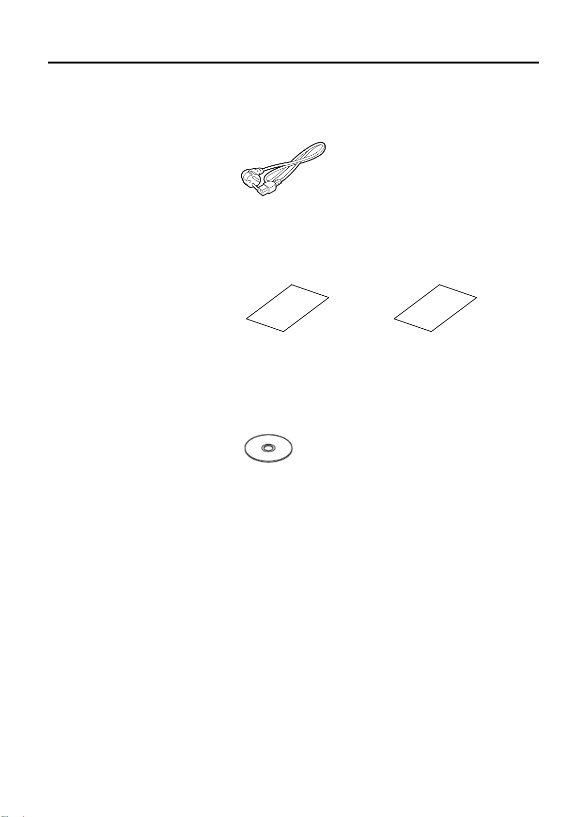
1.4 Accessories
1.4 Accessories
When unpacking the printer, please make sure all the following
accessories are supplied with the printer.
Power cord
Safety & Warranty Sheet
Setup Guide
CD-ROM(1pc.)
E1- 2
1. PRODUCT OVERVIEW
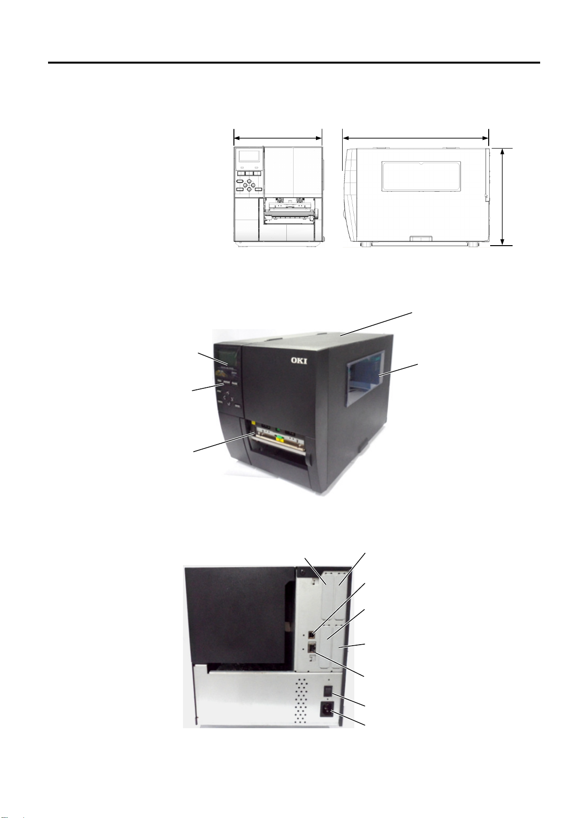
278
(10.9) 460 (18.1)
310
1.5 Appearance
1.5.1 Dimensions
1.5.2 Front View
LCD Message Display
Operation Panel
Media Outlet
1.5 Appearance
The names of the parts or units introduced in this section are used in the
following chapters.
(12.2)
Dimensions in mm (inches)
Top Cover
Supply Window
1.5.3 Rear View
Re
served for Parallel Interface
E1- 3
Reserved for Serial or
WLAN Interface
USB Interface
Reserved for USB Host
Interface
Reserved for Expansion I/O
interface
LAN Interface (Available for
only Ethernet model)
Power Switch
AC Power Inlet
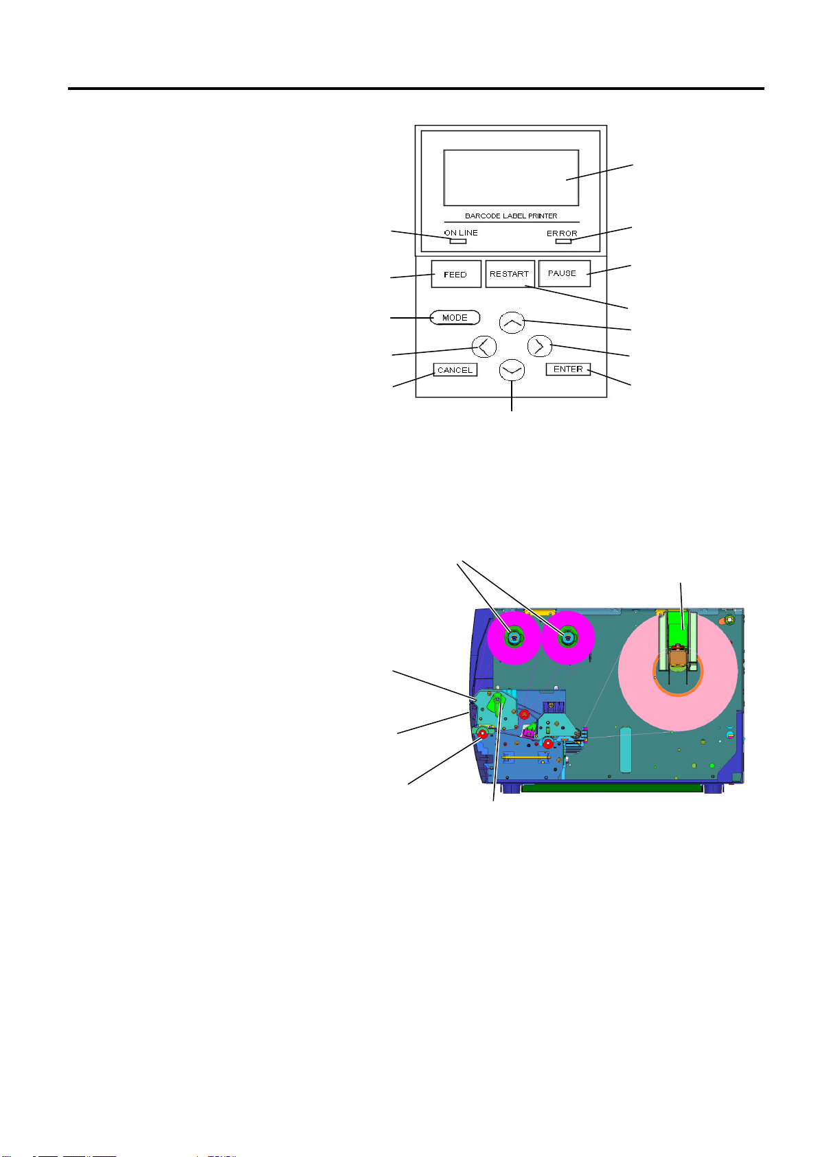
1. PRODUCT OVERVIEW
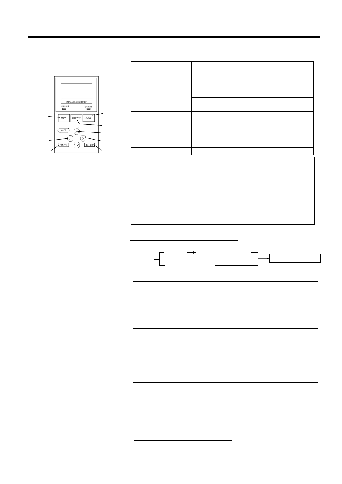
LCD
ERROR LED
PAUSE
RESTART
UP
RIGHT
ENTER
DOWN
CANCEL
MODE
LEFT
FEED
ONLINE LED
1.5.4 Operation Panel
1.5.5 Interior
1.5 Appearance
Please see Section 3 for further information about the Operation Panel.
Ribbon Shaft
Paper Guide R
Print Head Block
Print Head
Platen
Head Lever
E1- 4

1. PRODUCT OVERVIEW
1.6 Options
Cutter module Each time media is cut, the media feed is stopped.
Strip module This allows use of on-demand (peel-off) operation or to
203-dpi print head This print head enables a conversion of a 300dpi print head
300-dpi print head This print head enables a conversion of a 203dpi print head
RTC & USB host
interface card
Expansion I/O interface
card
Parallel interface card Installing this card provides a Centronics interface port.
Option Name Description
take-up labels and backing paper together when using the
rewind guide plate. To purchase the strip module, please
inquire with your local distributor.
of the LE850 model into 203dpi print head.
of the LE840 model into 300dpi print head.
This card holds the current time: year, month, day, hour,
minute, second and provides a USB host interface.
Installing this card in the printer allows connection to an
external device with the exclusive interface.
1.6 Options
Serial interface card Installing this card provides an RS-232C interface port.
RFID module mount
kit
Wireless LAN interface
card
This kit is to mount Tagsys HF band RFID
module and antenna.
Installing this card provides Wireless LAN communication.
NOTE:
To purchase the optional kits, please contact the nearest authorised Oki Data representative or Oki Data Head
Quarters.
E1- 5
2. PRINTER SETUP
Af
ter referring to the Safety Precautions in this
If the print start position cannot be detected
If the print start position cannot be detected
2. PRINTER SETUP
2. PRINTER SETUP
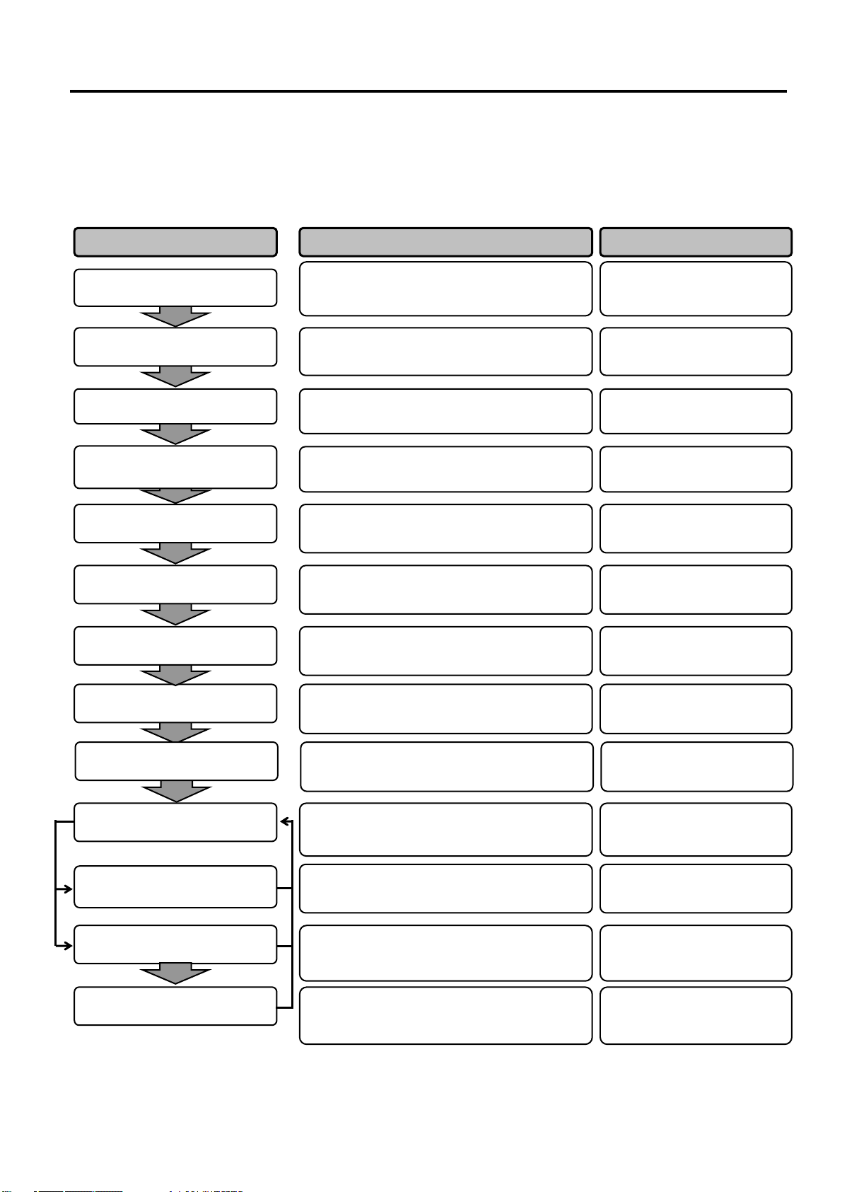
This section outlines the procedures to setup your printer prior to its operation. The section includes precautions,
loading media and ribbon, connecting cables, setting the operating environment of the printer and performing an
online print test.
Installation
Connecting the power cord
Loading the media
Media sensor position
alignment
manual, install the printer in a safe and stable
location.
Connect a power cord to the power inlet of the
printer, then to an AC outlet.
Load a label stock or tag stock.
Adjust the position of gap sensor or black mark
sensor according to the media being used.
2.1 Installation
2.2 Connecting the Power
2.3.1 Loading the Media
2.3.1 Loading the Media
Reference Procedure Setup Flow
Cord
Loading the ribbon
Connecting to a host computer
Turning the power ON
Printer setting
Installing the printer driver
Print test
Position and Print Tone Fine
adjustment
If using thermal transfer media then load the
ribbon.
Connect the printer to a host computer or
network.
Turn on the printer power.
Set the printer parameters in the system mode.
If necessary, install the printer driver on your
host computer.
Make a print test from your operating
environment and check the print result.
If necessary, fine adjust the print start position,
cut/strip position, print tone, etc.
2.3.2 Loading the Ribbon
2.4 Connecting the Cables to
Your Printer
2.5 Turning the Printer
ON/OFF
2.6 Printer Setting
2.7 Installing the Printer
Drivers
2.8 Print Test
2.9 Position and Print Tone
Fine Adjustment
Automatic threshold setting
Manual threshold setting
properly when pre-printed label are used, set the
threshold automatically.
properly even after automatic threshold setting is
performed manually set the threshold.
E2- 1
2.10 Threshold Setting
2.10 Threshold Setting

2. PRINTER SETUP
2.1 Installation
2.1 Installation
To insure the best operating environment and to assure the safety of the
operator and equipment, please observe the following precautions.
• Operate the printer on a stable, level surface in a location free from
excessive humidity, high temperature, dust, vibration and direct
sunlight.
• Keep your work environment static free. Static discharge can cause
damage to delicate internal components.
• Make sure the printer is connected to a clean source of AC power and
no other high-voltage devices, that may cause line noise interference,
are connected to the same mains.
• Assure that the printer is connected to the AC mains with a three-
prong power cable that has the proper ground (earth) connection.
• Do not operate the printer with the cover open. Be careful not to
allow fingers or articles of clothing to get caught in any of the
moving parts, especially the optional cutter mechanism.
• For best results, and longer printer life, use only Oki Data
recommended media and ribbons.
• Store the media and ribbons in accordance with their specifications.
• This printer mechanism contains high-voltage components; therefore
you should never remove any of the covers of the machine as you
may receive an electrical shock. Additionally, the printer contains
many delicate components that may be damaged if accessed by
unauthorised personnel.
• Clean the outside of the printer with a clean, dry cloth or a clean cloth
slightly dampened with a mild detergent solution.
• Use caution when cleaning the thermal print head as it will become
very hot while printing. Wait until it has had time to cool before
cleaning. Use only the Oki Data recommended print head cleaner to
clean the print head.
• Do not turn off the printer power or remove the power plug while the
printer is printing or while the ON LINE lamp is flashing.
E2- 2
2. PRINTER SETUP
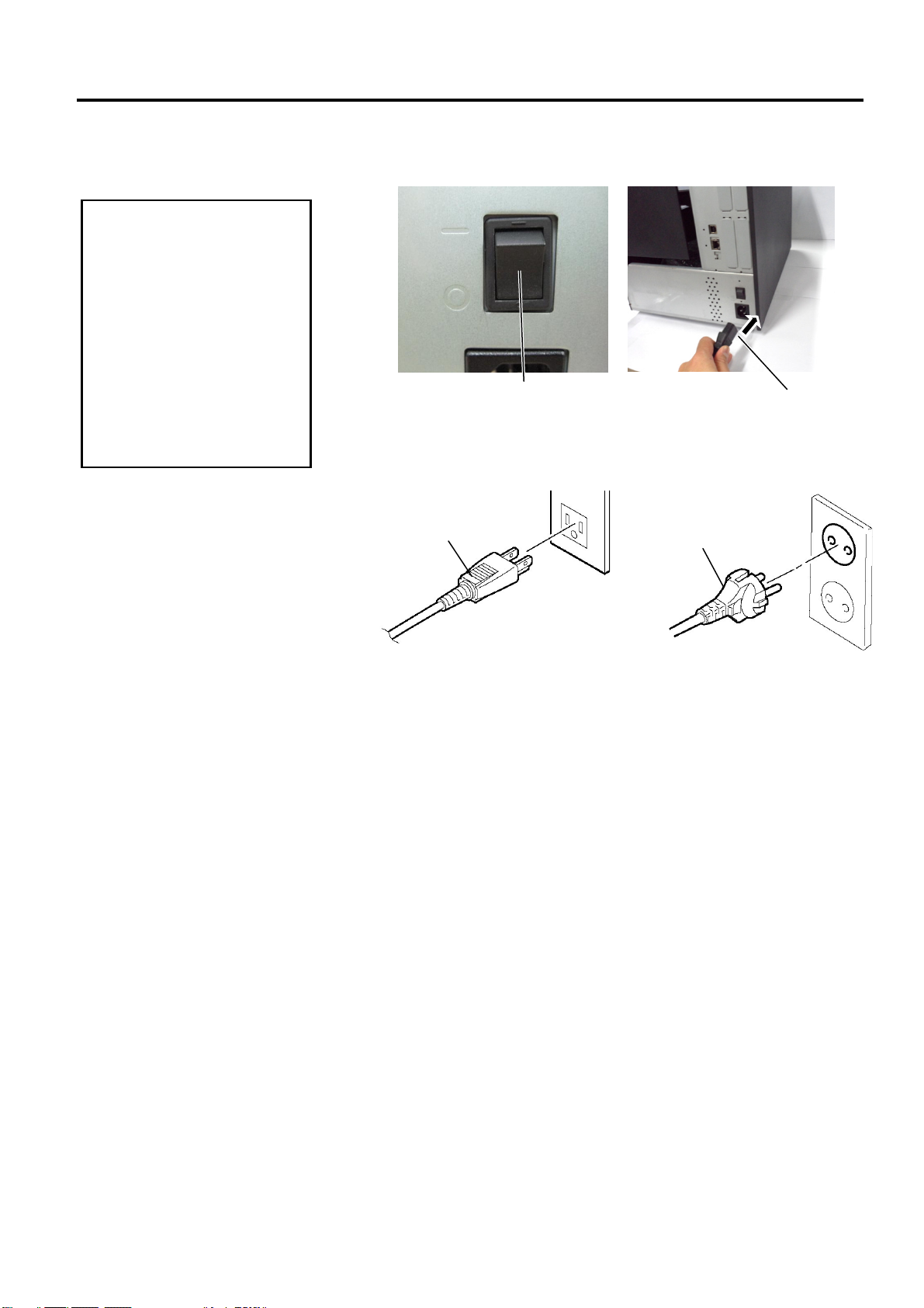
2.2 Connecting the Power Cord
1. Make sure that the printer
2. Connect the Power Cord
CAUTION!
Power Switch is turned to
the OFF position ()
before connecting the
Power Cord to prevent
possible electric shock or
damage to the printer.
to a supply outlet with a
properly grounded
(earthed) connection.
2.2 Connecting the Power Cord
1. Make sure that the printer Power Switch is in the OFF () position.
Connect the Power Cord to the printer as shown in the figure below.
Power Switch
Power Cord
2. Plug the other end of the Power Cord into a grounded outlet as shown
in the figure below.
Power Cord
Power Cord
[Example of US Type] [Example of EU Type]
E2- 3
2. PRINTER SETUP
2.3 Loading Supplies
2.3 Loading Supplies
1. Do not touch any moving parts, projection and the edge of sheet metal. To reduce the risk of
fingers, jewellery, clothing, etc., being drawn into the moving parts, be sure to load the supplies
once the printer has stopped moving completely.
2. The Print Head becomes hot immediately after printing, allow it to cool before loading the media.
3. To avoid injury, be careful not to trap your fingers while opening or closing the cover.
WARNING!
CAUTION!
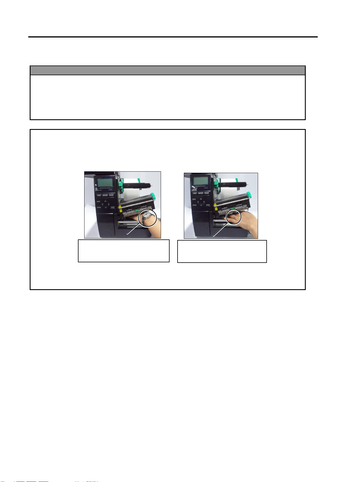
1. Be careful not to touch the Print Head Elements when lifting the Print Head Block. This may
cause missing dots due to static electricity or other print quality problems.
2. When loading or replacing the media or ribbon, be careful not to damage the print head with hard
objects like watches or rings.
Since the print head element can be easily damaged by shock, please treat it carefully and do not
hit it with hard objects.
Care must be taken not to allow
the metal or glass part of a watch
to touch the print head edge.
Care must be taken not to allow a
metal object like a ring to touch
the print head edge.
E2- 4
2. PRINTER SETUP
TAG
LABEL
FREE
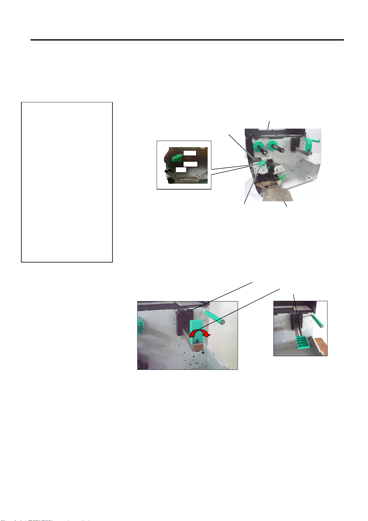
2.3.1 Loading the Media
1. When the Head Lever is
turned to
Print Head can be raised.
2. To enable printing the Head
Lever must be set to the
LABEL / TAG
(This ensures that the Print
Head is closed.)
There are two head pressure
levels in the
position. Set the Head Lever
depending on the media type:
Position LABEL: Labels
Position TAG : Tags
However, proper position
may differ depending on
media. For details, refer to
your Oki Data authorised
service representative.
NOTES:
FREE
position, the
position.
LABEL / TAG
2.3 Loading Supplies
The following procedure shows the steps to properly load the media into
the printer so that it feeds straight through the printer.
The printer prints both labels and tags.
1. Open the Top Cover.
2. Turn the Head Lever to the FREE position and release the Ribbon
Shaft Holder Plate.
3. Open the Print Head Block.
Print Head Block
Top Cover
Head
Lever
Ribbon Shaft Holder Plate
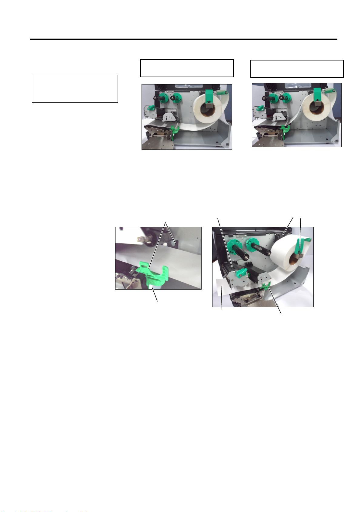
4.
Move the Paper guide R to the rightmost position or shift the
guide to the horizontal position.
Paper Guide L
Paper Guide R
5. Put the media on the Paper Holder.
6. Pass the media around the Paper Holder, and then pull
the media towards the front of the printer.
7. Push the Paper Guide against the media until the media is
held firmly in place. To lock the Media, shift the Paper Guide
R to vertical position
E2- 5
2. PRINTER SETUP
2.3.1 Loading the Media
(Cont.)
Do not over-tighten the Locking
Ring of the Supply Holder.
NOTE:
2.3 Loading Supplies
In the case of labels rolled with
the print side facing inside.
In the case of labels rolled with
the print side facing outside.
8. Place the media between the Media Guides and adjust them to the
media width. Once in the correct position tighten the Locking
Screw.
9. Check that the media’s path through the printer is straight. The
media should be to the left side of the print head
Media Guide
Print Head
Paper Guide
Locking Screw
Media
Media Guide
E2- 6
2. PRINTER SETUP
jam or no paper error may occur.
2.3.1 Loading the Media
(Cont.)
NOTE:
Be sure to set the black mark
sensor to detect the centre of the
black mark, otherwise a paper
2.3 Loading Supplies
10. Lower the Print Head Block.
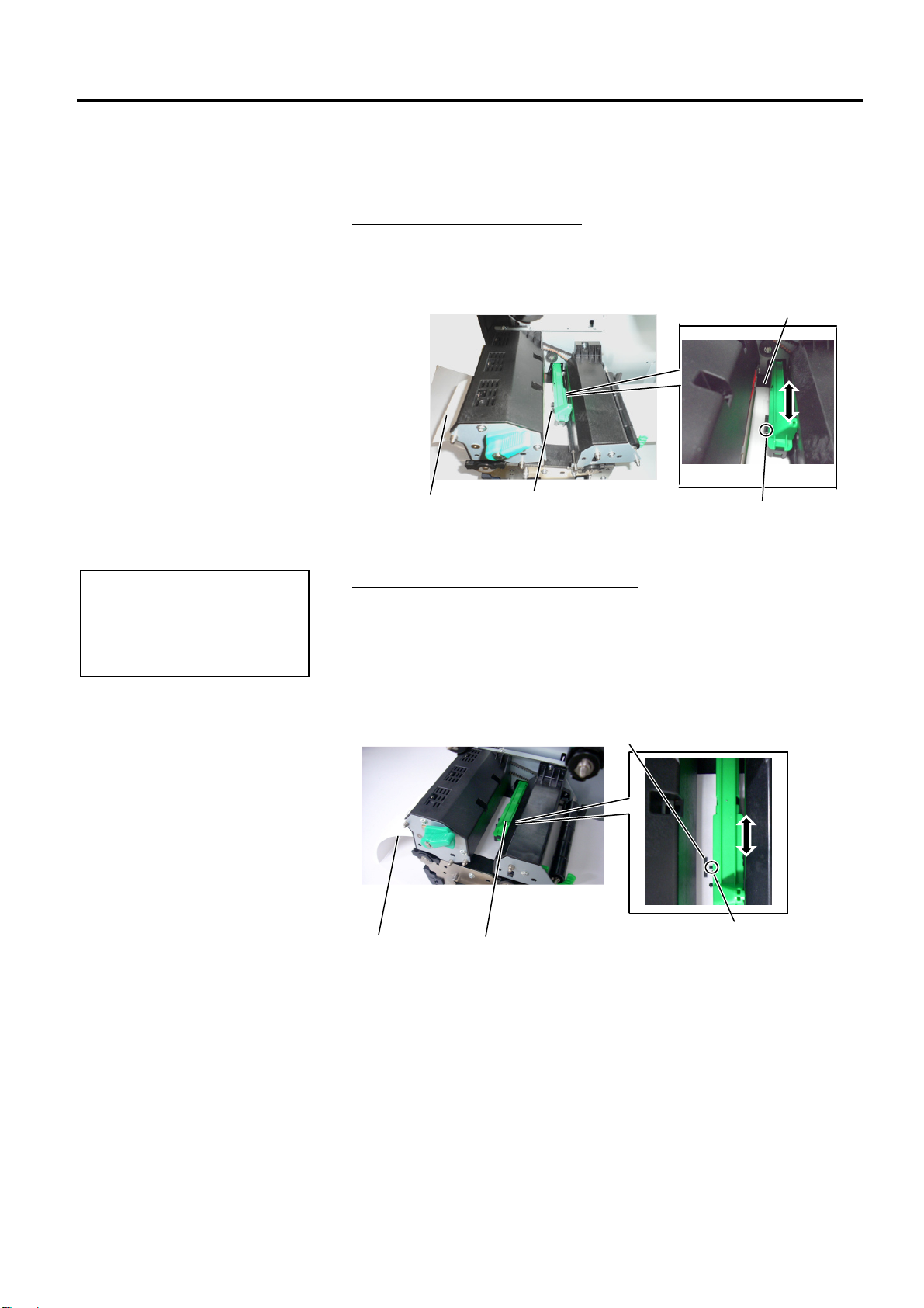
11. Once the media is loaded it may be necessary to set the Media
Sensors used to detect the start position for label or tag.
Setting the Gap Sensor position
(1) Manually move the Media Sensor so that the Gap Sensor is
positioned at the centre of the labels. ( indicates the position of the
Gap Sensor).
Gap
Label Media Sensor
Gap Sensor ()
Setting the Black Mark Sensor position
(1) Pull about 500 mm of media out of the front of the printer, turn the
media back on itself and feed it under the Print Head past the sensor
so that the black mark can be seen from above.
(2) Manually move the Media Sensor so that the Black Mark Sensor is
in line with the centre of the black mark on the media. ( indicates
the position of the Black Mark Sensor).
Black Mark
Media
Media Sensor
E2- 7
Black Mark Sensor (
)
2. PRINTER SETUP
2.3.1 Loading the Media
(Cont.)
NOTES:
1. Be sure to set the Selection
Switch to STANDARD/
PEEL OFF position.
2. The backing paper is easier
to feed back to the Take-Up
Spool if the Front Plate is
removed.
3. Fit the Take-Up Clip so that
the longer side of the clip is
fitted into the shallow groove
in the Take-Up Spool.
4. The backing paper can be
wound directly onto the
Take-up Spool or a paper
core.
Strip Plate
2.3 Loading Supplies
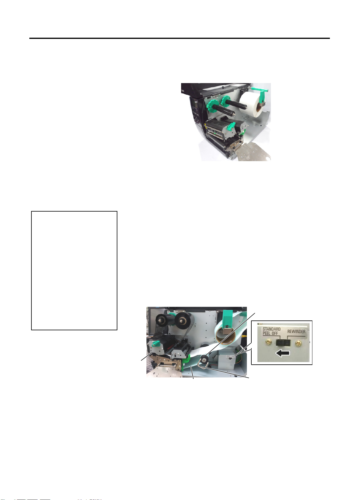
12. Batch mode
In batch mode, the media is continuously printed until the number of
labels/tags specified in the issue command has been printed.
13. Loading with peel off module
When the optional Strip Module is fitted, the label is automatically
removed from the backing paper at the Strip Plate as each label is
printed.
(1) Remove enough labels from the leading edge of the media to leave
500mm of backing paper free.
(2) Insert the backing paper under the Strip Plate.
(3) Wind the backing paper onto the Take-up Spool and fix it in position
with the Take-up Clip. (Wind the paper counter-clockwise around
the spool.)
(4) Rotate the Take-up Spool counter-clockwise a few times to remove
any slack in the backing paper.
(5) Set the Selection Switch mounted on the Rewinder Assembly to
STANDARD/PEEL OFF position.
Take-up Spool
Backing Paper
Take-up Clip
E2- 8
2. PRINTER SETUP
CAUTION!
labels will cause the glue to
may affect the cutter quality
Cutter Module
2.3.1 Loading the Media (Cont.)
The cutter is sharp, so care
must be taken not to injure
yourself when handling the
cutter.
1. Be sure to cut the backing
paper of the label. Cutting
stick to the cutter which
and shorten the cutter life.
2. Use of tag paper when the
thickness exceeds the
specified value may affect
the cutter life.
WARNING!
2.3 Loading Supplies
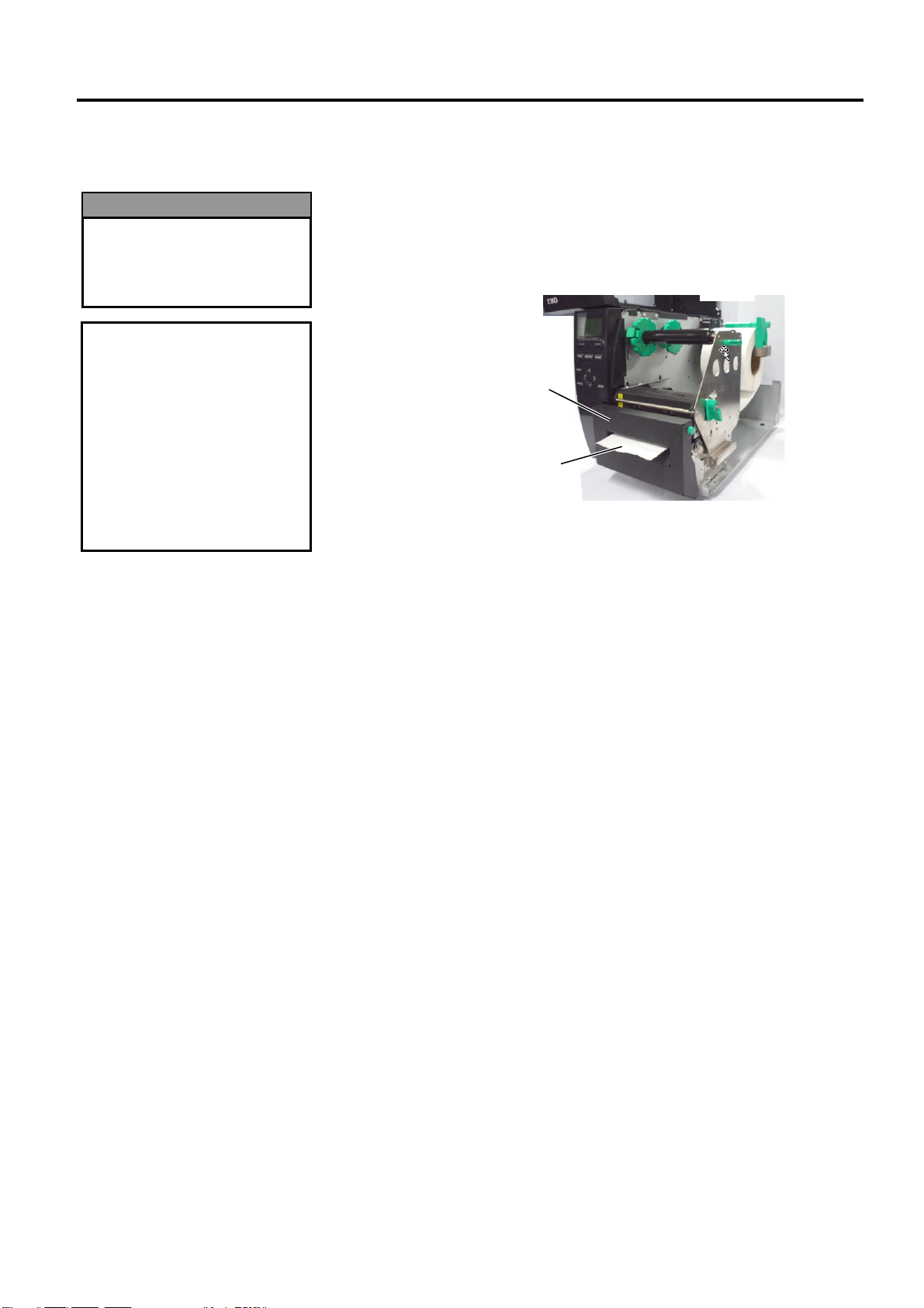
14. Loading with cutter
When the optional Cutter Module is fitted, the media is
automatically cut. A disc cutter is available as option.
Insert the leading edge of the media into the cutter until it comes out
the Media Outlet of the Cutter Module.
Media Outlet
E2- 9
2. PRINTER SETUP
Be sure to remove any slack in
Print H
ead Block
Outside
Wound Ribbon
Inside
Wound Ribbon
2.3.2 Loading the Ribbon
1. When attaching the ribbon
stoppers, make sure that the
pinchers face into the printer
2.
the ribbon before printing.
Printing with a wrinkled
ribbon will reduce the print
quality.
3. The Ribbon Sensor is mounted
on the rear of the Print Head
Block to detect a ribbon end.
When a ribbon end is detected
a “NO RIBBON” message
will appear on the display and
the ERROR LED will
illuminate.
NOTES:
2.3 Loading Supplies
There are two types of media available for printing on: thermal transfer
and direct thermal (which has a chemically treated surface). DO NOT
LOAD a ribbon when using direct thermal media.
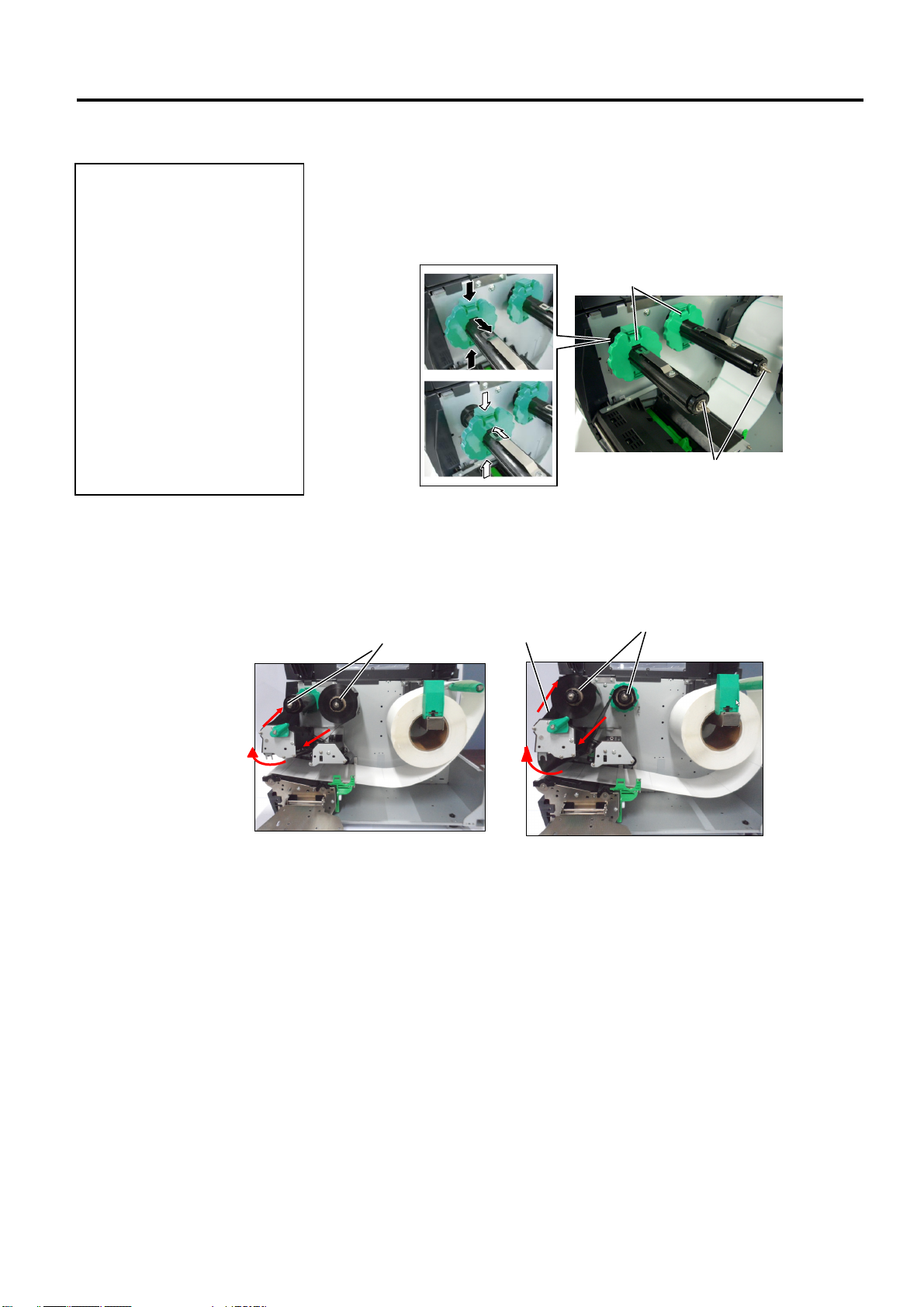
1. Grasp the tabs on the top and bottom of the Ribbon Stoppers and move
the Ribbon Stoppers back to the end of the Ribbon Shaft.
Ribbon Stopper
Ribbon Shaft
2. Leaving plenty of slack between the ribbon spools, place the ribbon
onto the Ribbon Shafts as shown below.
load the ribbon.
There are 2 possible ways to
Ribbon Shaft
Ribbon Shaft
NOTE:
To check or change settings on which type of Ribbon winding to be used, you
must go to SYSTEM Mode in the Printer. For more details refer to Key
Operation Manual, “8.4.1 PRINTER SET”.
E2-10
2. PRINTER SETUP
2.3.2 Loading the Ribbon
(Cont.)
2.3 Loading Supplies
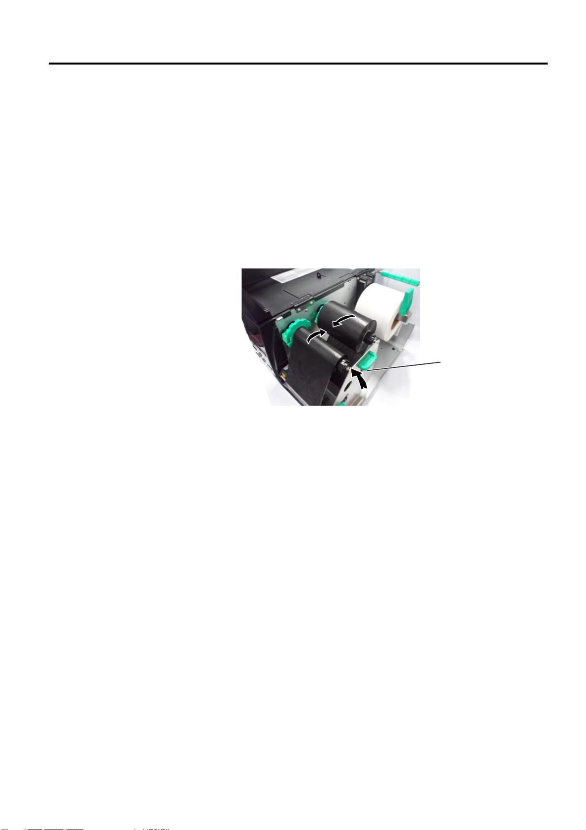
3. Push Ribbon along the Ribbon Shafts to a position where the ribbon is
fully to the Left against the stoppers when fitted.
4. Lower the Print Head Block and set the Ribbon Shaft Holder
Plate aligning its holes with the Ribbon Shafts.
5. Take up any slack in the ribbon. Wind the leading tape onto the
ribbon take-up roll until the ink ribbon can be seen from the
front of the printer.
Ribbon Shaft Holder Plate
6. Turn the Head Lever to Lock position to close the Print Head.
7. Close the Top Cover.
E2-11
2. PRINTER SETUP
USB
I
nterfa
ce
2.4 Connecting the Cables to Your Printer
2.4 Connecting the Cables to Your Printer
The following paragraphs outline how to connect the cables from the
printer to your host computer, and will also show how to make cable
connections to other devices. Depending on the application software
you use to print labels, there are 5 ways to connect the printer to your
host computer. These are:
• An Ethernet connection using the printer’s standard LAN
connector.
• A USB cable connection between the printer’s standard USB
connector and your host computer’s USB port. (Conforming to
USB 2.0)
• A serial cable connection between the printer’s optional RS-232
serial connector and one of your host computer’s COM ports.
• A parallel cable connection between the printer’s optional parallel
connector and your host computer’s parallel port (LPT).
• Wireless LAN using an optional Wireless LAN board.
For details, refer to APPENDIX 2.
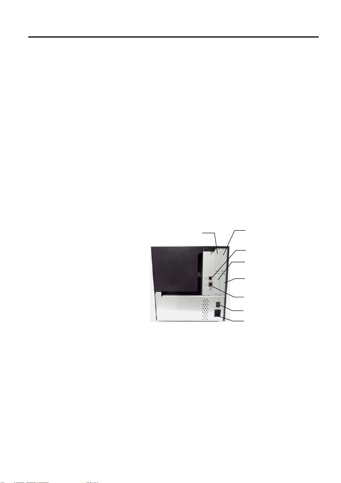
Reserved for
Parallel Interface
Reserved for Serial or
WLAN Interface
Reserved for USB Host
interface
Reserved for
Expansion I/O Interface
LAN Interface (Available
for Ethernet model only)
Power Switch
AC Power Inlet
E2-12
2. PRINTER SETUP
2.5 Turning the Printer ON/OFF
2.5.1 Turning ON the Printer
• Use the power switch to
• Do not turn on the printer
If a message other than ON
LINE appears on the display or
the ERROR LED lamp is
illuminated, refer to Section 5.1,
Error Messages.
2.5.2 Turning OFF the Printer
1. Do not turn off the printer
2. Do not turn off the printer
CAUTION!
turn the printer On/Off.
Plugging or unplugging the
Power Cord to turn the
printer On/Off may cause
fire, an electric shock, or
damage to the printer.
power while the ON LINE
and ERROR lamp are
blinking as this may cause
damage to the printer.
CAUTION!
power while the media is
being printed, as this may
cause a paper jam or
damage to the printer.
power while the ON LINE
lamp is blinking as this
may cause damage to
your computer.
NOTE:
2.5 Turning the Printer ON/OFF
When the printer is connected to your host computer it is good practice to
turn the printer ON before turning on your host computer and turn OFF
your host computer before turning off the printer.
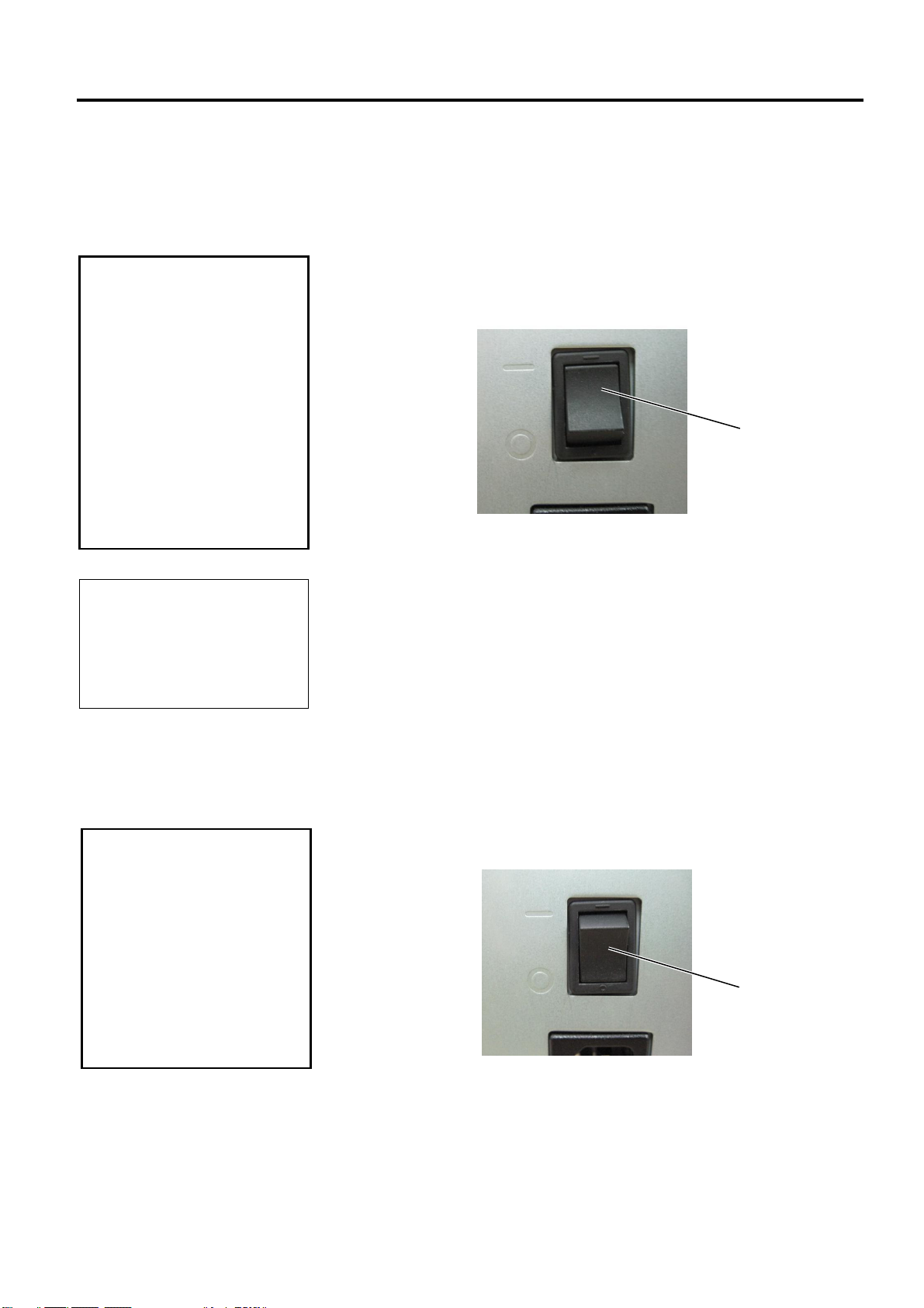
1. To turn ON the printer power, press the Power Switch as shown in the
diagram below. Note that ( | ) is the power ON side of the switch.
Power Switch
2. Check that the ON LINE message appears in the LCD Message
Display and that the ON LINE and POWER LED lights are
illuminated.
1. Before turning off the printer Power Switch verify that the ON LINE
message appears in the LCD Message Display and that the ON LINE
LED light is on and is not flashing.
2. To turn OFF the printer power press the Power Switch as shown in the
diagram below. Note that () is the power OFF side of the switch.
Power Switch
E2-13
2. PRINTER SETUP
2.6 Printer Setting
Power ON
Power OFF
Depending on the settings of your host computer or the interface being
used it may be necessary to change the printer parameter settings.
Follow the procedures described below to change the printer parameter
settings to correspond to your environment.
Incorrect settings can cause the printer not to function correctly. If you
have any problems with the parameter settings, please contact your nearest
Oki Data service representative.
For the settings this manual does not cover, please contact your nearest Oki
Data service representative, or refer to the LE840/LE850 Key Operation
Manual.
ONLINE Mode
[PAUSE]
PAUSE state
NOTE:
2.6 Printer Setting
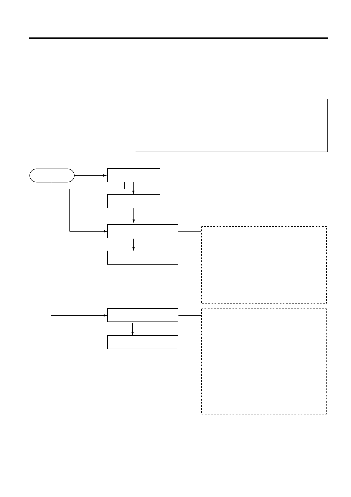
User System Mode
Hold down [MODE]
Reboot the printer
Turn on the power while holding
down [FEED] & [PAUSE] or
[MODE].
System Mode
Select [RESET] menu
Reboot the printer
Hold down [RESTART]
Select [RESET] menu
Reset
Parameter setting (Section 2.6.2)
Fine adjustment (Section 2.9)
LAN/WLAN (Section 2.6.3)
BASIC (Section 2.6.4)
Z-MODE (Section 2.6.5)
Auto calibration (Section 2.6.6)
Dump mode (Section 2.6.7)
Log (Section 2.6.8)
Self diagnosis
Parameter setting
Fine adjustment
Test print
Sensor adjustment
RAM clear
Interface setting (Section 2.6.10)
BASIC mode
RFID setting
Real Time Clock (Section 2.6.11)
Z-MODE
USB memory (Section 2.6.12)
Reset
E2-14
2. PRINTER SETUP
2.6 Printer Setting
(Cont.)
FEED
MODE
LEFT
CANCEL
DOWN
PAUSE
RESTART
UP
RIGHT
ENTER
2.6.1 User System Mode
2.6 Printer Setting
Key functions in system mode
Key Function
[MODE] Returns to the system mode menu.
[CANCEL] or
[FEED]+[RESTART]
[LEFT] Moves the cursor to the left.
[RIGHT] Moves the cursor to the right.
1. The cursor will not scroll from the bottom to the top or top to bottom
of a menu.
2. The value will not increase or decrease any further than the maximum
or minimum values of a parameter.
3. The cursor will not move any further than the left- or right-most
positions of a field.
4. Any values changed will not become effective if the printer is turned
off without pressing the [ENTER] key.
Returns to the previous menu.
Displays the next screen. [ENTER] or [PAUSE]
Saves the settings and returns to the previous
menu.
Moves the cursor up.
Increases a value.
Moves the cursor down.
Decreases a value.
NOTES:
(Note 1)
(Note 2)
(Note 3)
(Note 1)
[UP] or [RESTART]
(Note 3)
[DOWN] or [FEED]
(Note 3)
How to enter the User System Mode
ONLINE
[PAUSE] Hold down [RESTART]
Hold down [MODE]
User System Mode
The User System Mode consists of the following menus.
<1>RESET
Used to reboot the printer.
<2>PARAMETER SET ( Section 2.6.2)
Used to set the printer parameters.
<3>ADJUST SET ( Section 2.9)
Used to fine adjust the print start position, cut position, etc.
<4>LAN/WLAN ( Section 2.6.3)
Used to enable or disable the LAN communication and SNMP.
<5>BASIC ( Section 2.6.4)
Used to set the function of basic program when it is loaded to the
printer.
<6>Z-MODE ( Section 2.6.5)
Same as BASIC
<7>AUTO CALIB ( Section 2.6.6)
Used to enable or disable the automatic calibration function.
<8>DUMP MODE ( Section 2.6.6)
Used to print the data in the receive buffer for debugging purposes.
<9>LOG ( Section 2.6.7)
Used to save print logs in USB memory.
How to exit the User System Mode
Select <1> RESET menu to reboot the printer.
E2-15
2. PRINTER SETUP
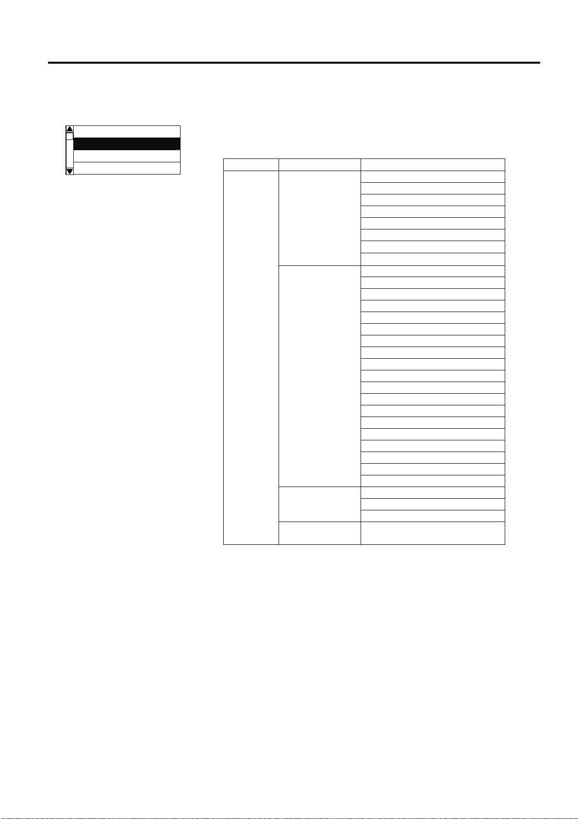
2.6.2 Parameter Setting
USER SYSTEM MODE
<1>RESET
<2>PARAMETER SET
<3>ADJUST SET
<4>LAN/WLAN
2.6 Printer Setting
The Parameter Set menu allows the printer parameter settings to be
modified.
The following table shows the contents of the Parameter Set menu.
Contents of the Parameter Set Menu
Menu Sub menu Parameter
Printer Set MEDIA LOAD Parameter
set
FW/BK ACT
HU CUT/RWD
RBN SAVE
PRE PEEL OFF
Software Set FONT CODE
(Section 2.6.2.2) ZERO FONT
CODE
PEEL OFF STATUS
USB I/F STATUS
FEED KEY
KANJI CODE
EURO CODE
AUTO HD CHK
WEB PRINTER
RBN NEAR END
EX I/O
LBL/RBN END
MAX CODE
XML
THRESHOLD SELECT
ENERGY TYPE
PW SAVE TIME
RIBBON WIDTH
Panel LCD LANGUAGE
(Section 2.6.2.3) DISPLAY
CONTRAST
Password PASSWORD
(Section 2.6.2.4)
(Section 2.6.2.1) FORWARD WAIT
BACK SPEED
TYPE OF RIBBON
E2-16
Loading...