


FR-D700
Table of contents
 Loading...
•
Features
•
Standard
specifications
•
Outline
dimension
drawings
•
Terminal connection
diagram
•
Terminal specification
explanation
•
Operation panel
•
Parameter unit
•
Parameter list
•
Protective
functions
•
Option and
peripheral devices
•
Precautions for
operation/selection
•
Precautions for peripheral
device selection
1
5
7
•
FR-D700 Series
Specification
Difference List
32
•
Warranty
•
International
FA Center
33
11
13
16
23
24
27
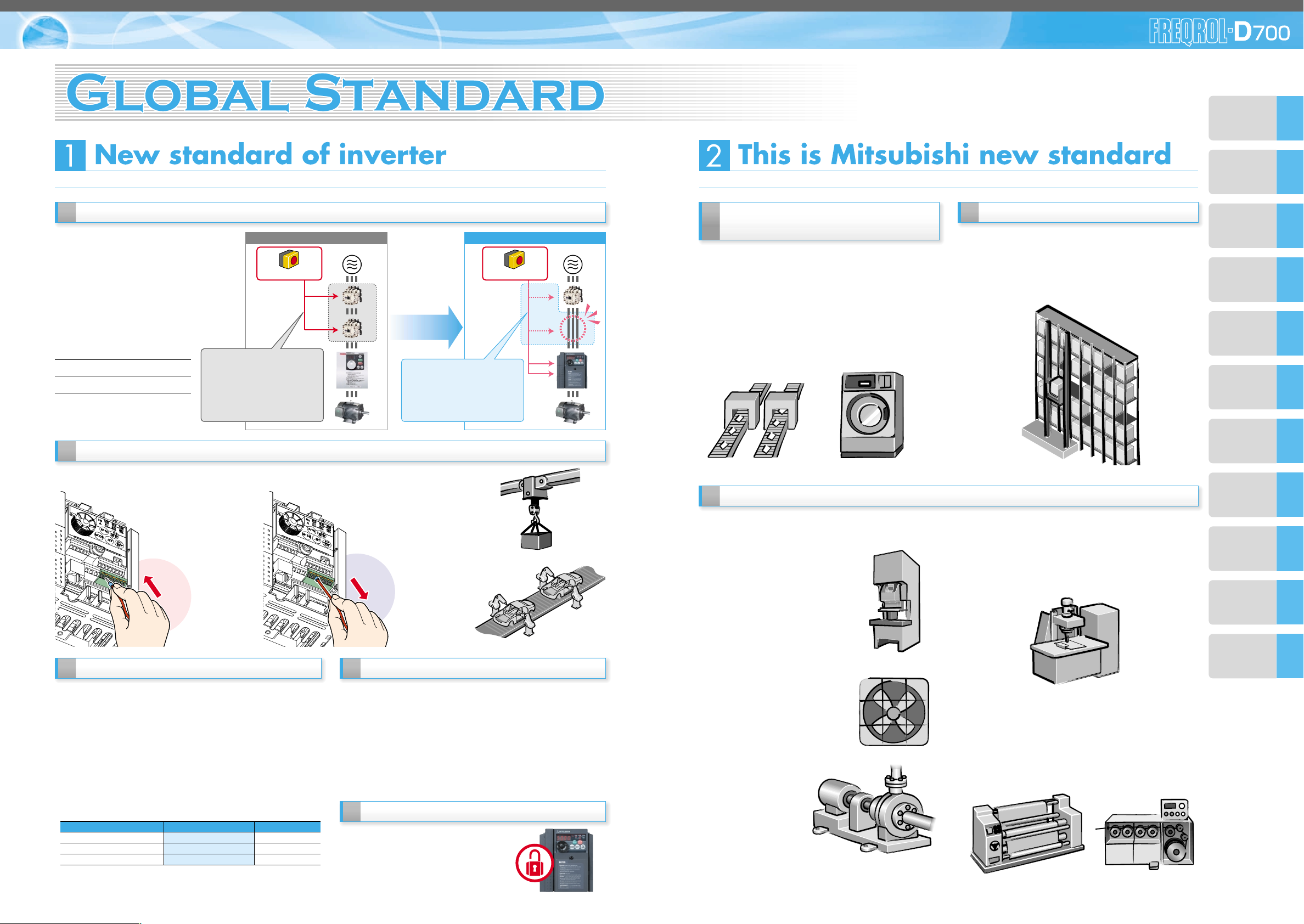
High reliability is realized!
Safety stop function
Spring clamp terminal (control circuit terminal)
Long-life design
The FR-D700 series is compliant to the EU
Machinery Directive without the addition of
previously required external devices.
Operation of an external Emergency
Stop device results in a highly reliable
immediate shutoff of the D700's output to
the motor.
This safety stop function conforms to the
following standards.
Enhanced function
Equipped with small class highest level of function/performance!!
150%/1Hz high starting torque by general
-purpose magnetic flux vector control
General-purpose magnetic flux vector control and auto
tuning function are available.
It ensures operation that requires high starting torque,
such as transfer machine including conveyer, hoist, lift,
etc., washing machine, and agitators.
•
High torque 150%/1Hz and 200%/3Hz are realized
•
Auto tuning
Many kinds of motors can be optimally controlled with
Mitsubishi original "non-rotation " auto tuning function.
(R1 constants tuning)
Brake resistor can be connected
A brake transistor is built-in to the 0.4K or more.
Connecting an optional brake resistor increases
regeneration capability.
It is useful for deceleration time reduction of a machine
with a large inertia, such as fan, and operation of lift, etc.
Highly reliable and easy wiring is realized by the incorporation of spring clamp terminals.*
•
The design life of the cooling fan has been extended to 10
years
*1
. The life of the fan can be further extended utilizing the
it’s ON/OFF.
•
The longevity of the capacitors has been extended to 10
years by the adoption of a capacitor with a specification of
5000 hours and 105˚C surrounding air temperature
*1,*2
.
Most advanced life check
•
Degrees of deterioration of main circuit capacitor, control
circuit capacitor, and inrush current limit circuit can be
monitored.
•
Trouble can be avoided with the self-diagnostic alarm
*4
that is
output when the life span is near.
Password function
Registering 4-digit password can limit
parameter read/write.
It is effective for parameter setting
protection.
EN954-1 (ISO13849-1) Category 3
IEC60204-1 Stop Categor y 0
*: Main circuit terminal is screw terminal.
Provided by the user (present) FR-D700
Safety function
is equipped
Emergency stop
(example: automobile production line)
(example: hoist)
*1: Surrounding air temperature : annual average 40˚C (free from corrosive gas,
flammable gas, oil mist, dust and dirt) Since the design life is a calculated value, it is
not a guaranteed value.
*2: Output current : 80% of the inverter rated current
*3: Excerpts from "Periodic check of the transistorized inverter" of JEMA (Japan Electrical
Manufacturerís Association)
*4: If any one of main circuit capacitor, control circuit capacitor, inrush current restriction
circuit or cooling fan reaches the output level, an alarm is output. Capacity of the main
circuit capacitor can be measured by setting parameter at a stop and turning the
power from off to on. Measuring the capacity enables alarm to be output.
The cooling fan outputs alarm by using fan speed detection.
•
Life indication of critical components
Components
Cooling fan
Main circuit smoothing capacitor
Printed board smoothing capacitor
Guideline of the FR-D700 Life
10 years
10 years
10 years
Guideline of JEMA
*3
2 to 3 years
5 years
5 years
Emergency stop
Only one MC is enough Only one MC is enough
with safety stop function!with safety stop function!
Only one MC is enough
with safety stop function!
•Cost reduction
•Maintenance of one MC
•Installation space is reduced
For conventional modelFor conventional model...
Two MCs are necessaryTwo MCs are necessary
For conventional model...
Two MCs are necessary
•High cost
•Maintenance of two MCs is
necessary
•Installation space is necessary
•
Magnetic contactor (MC)
•
Emergency stop wiring
(example:
industrial washing machine)
(example: conveyer)
(example: automated storage)
New functions and useful functions from superior models
support all sorts of applications.
•
Regeneration avoidance function
For a pressing machine and
fan rotated faster than the set
speed due to the effect of
another fan, a trip can be
made less likely to occur by
automatically increasing
frequency at regeneration.
•
Optimum excitation control
This control enables the motor
efficiency to its optimum. More
energy saving is possible in
applications with variable load
torque characteristic such as
fan and pump.
•
Power failure-time deceleration-to-stop function
The motor can be decelerated to a stop when a power
failure or undervoltage occurred to prevent the motor
from coasting.
For fail-safe of machine tool, etc., it is effective to stop
the motor when a power failure has occurred.
•
Dancer control
Entering position detection signal of dancer roll to use
PID control enables tension control by dancer roll.
•
Traverse function
Traverse function for wind-up drum of spinning
machine and wiredrawing machine prevents
unevenness and deformation at thread winding.
(example: air-conditioning fan)
(example: pump)
(example: pressing machine)
(example: spindle)
(example: textile machine) (example: wiredrawing machine)
(1) (1)
(3)
(2)
(2)
(3) (4)
(5)
1 2
•
High reliability
Spring structure in terminal contact
section inside prevents contact fault
by vibration.
•
Maintenance is unnecessary
Screw retightening is unnecessary.
•
Easy wiring
Wiring is completed only
by inserting wires treated
with bar terminal (max,
diameter 1.5mm)
Capable of wiring without
a bar terminal.
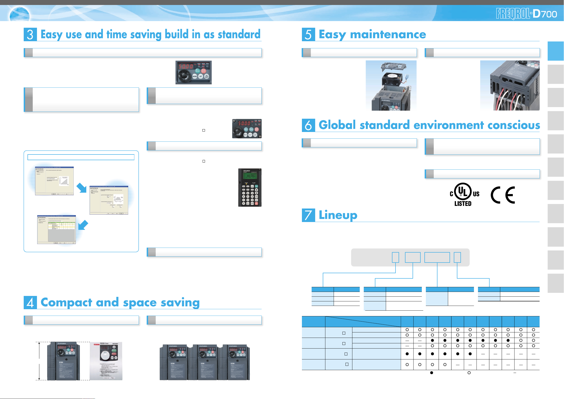
RoHS Directive compliant
Complies with UL, cUL,EN (LVD) standards
Human and environment-friendly inverter in compliant with
RoHS Directive.
The lineup of EMC filter integrated models.
The lineup of three phase 200V/400V class goes to 15K.
For the FR-D700 series, North American (NA), EU (EC), and Chinese (CHT) specifications also are supported.
Parameter unit FR-PU07 (option)
An optional parameter unit (FR-PU07) can be connected as well.
Enhanced communication function
•
Modbus and Mitsubishi inverter protocol
Supports Modbus RTU
Communication speed of RS-485 has been improved
(communication at 38.4kbps is available)
"Multi command mode" has been added to Mitsubishi inverter protocol
(data processing time of the inverter has been reduced to 1/4)
Setting is easily done from a personal
computer using the FR Configurator
(option) (available soon)
Connecting a personal computer and the inverter via RS-485
communication realizes setting with wizard (interactive) function
of the FR Configurator (inverter setup software).
In addition, a parameter setting can be converted from the FR-
S500 series to the FR-D700 series by "convert" function.
Displays monitor data in waveform. [Graph]
Enclosure surface operation panel
FR-PA07 (option)
Optional enclosure surface operation panel (FR-PA07) can be
connected. In addition, an operation panel for the FR-E500
series can be connected.
RoHS Directive requires member nations must guarantee that new electrical and electronic
equipment sold in the market after July 1, 2006 do not contain lead, cadmium, mercury,
hexavalent chromium, polybrominated biphenyl (PBB) and polybrominated diphenyl ether
(PBDE) flame retardants
<G> mark indicating RoHS Directive compliance is printed on the package.
Easily replaceable compact body
Installation size is the same as that of the FR-S500 series which
is the smallest model of the Mitsubishi inverter.
Side by side installation saves space
Space can be saved by side by side no clearance installation*.
Easy replacement of cooling fan
A cooling fan is provided on top
of the inverter of all capacities
requiring a cooling fan (1.5K or
more).
A cooling fan can be easily
replaced without disconnecting
main circuit wires.
Combed shaped wiring cover
Since a cover can be fitted
after wiring, wiring work is
easily done.
The operation panel of the inverter can not be removed.
A parameter unit connection cable (FR-CB20 ) is
separately necessary.
A parameter unit connection cable (FR-CB20 ) is separately necessary.
Quick setup with the setting dial
Mitsubishi inverter has a setting dial of course.
•
The scrolling speed of the dial was made to variable for more
improved operability.
•
The nonslip setting dial is easier to turn.
Acceleration/deceleration
pattern setting
Acceleration/deceleration
time setting
Parameter list display
Setting wizard function (example: acceleration/deceleration time setting)
128mm
FR-D740-0.4K FR-S540E-0.4K
*: Use the inverter at the surrounding air temperature of 40˚C or less.
*: This catalog explains based on the Japanese specifications.
Consult our sales office for specifications of each country.
FR-D740 -0.4K-
Inverter Type
Inverter Capacity
0.1 0.2 0.4 0.75 1.5 2.2 3.7 5.5 7.5
FR-D720- K
FR-D740- K
FR-D720S- K
FR-D710W- K
Three phase
200V
Three phase
400V
Single phase
200V
*
Single phase
100V *
Enclosed structure (IP20)
Totally-enclosed structure (IP40)
Enclosed structure (IP20)
Totally-enclosed structure (IP40)
Enclosed structure (IP20)
Enclosed structure (IP20)
11 15
*: Output of the single-phase 200V and single-phase 100V input models is three-phase 200V.
:Available models :Models to be released :Not available
Power
Supply
Symbol
1
2
4
Voltage
100V class
200V class
400V class
Symbol
None
C
Protective Structure
Enclosed-type structure IP20
Totally enclosed structure IP40
Symbol
0.1K to 15K
Inverter Capacity
Indicate capacity
"kW".
Symbol
None
S
W
Number of Power Phases
Three-phase input
Single-phase input
Single-phase input
(double voltage output)
(1) (1) (2)
(1)
(3)
(1) (2)
(2) (3)
EMC filter integrated model
(to be released)
(3)
(4)
(5)
3 4
FeaturesOptions
Standard
Specifications
Operation panel
Parameter unit
Parameter
List
Protective
Functions
Terminal Connection
Diagram
Terminal Specification
Explanation
Outline
Dimension
Drawings
Instructions
FR-D700 Series
Specification
Difference List
Warranty
International
FA Center
•
Setting such as direct input method with a numeric
keypad, operation status indication, and help
function are usable.
Eight languages can be displayed.
•
Parameter setting values of maximum of three
inverters can be stored.
•
A battery pack type (FR-PU07BB(-L)) allows
parameter setting and parameter copy without
powering on the inverter. (available soon)
•
To use a parameter unit with battery pack (FR-PU07BB)
outside Japan, order a “FR-PU07BB-L” (parameter unit type
indicated on the package has L at the end).
Since enclosed batteries may conflict with laws in countries to
be used (new EU Directive on batteries and accumulators, etc.),
batteries are not enclosed with an FR-PU07BB except Japan.
5
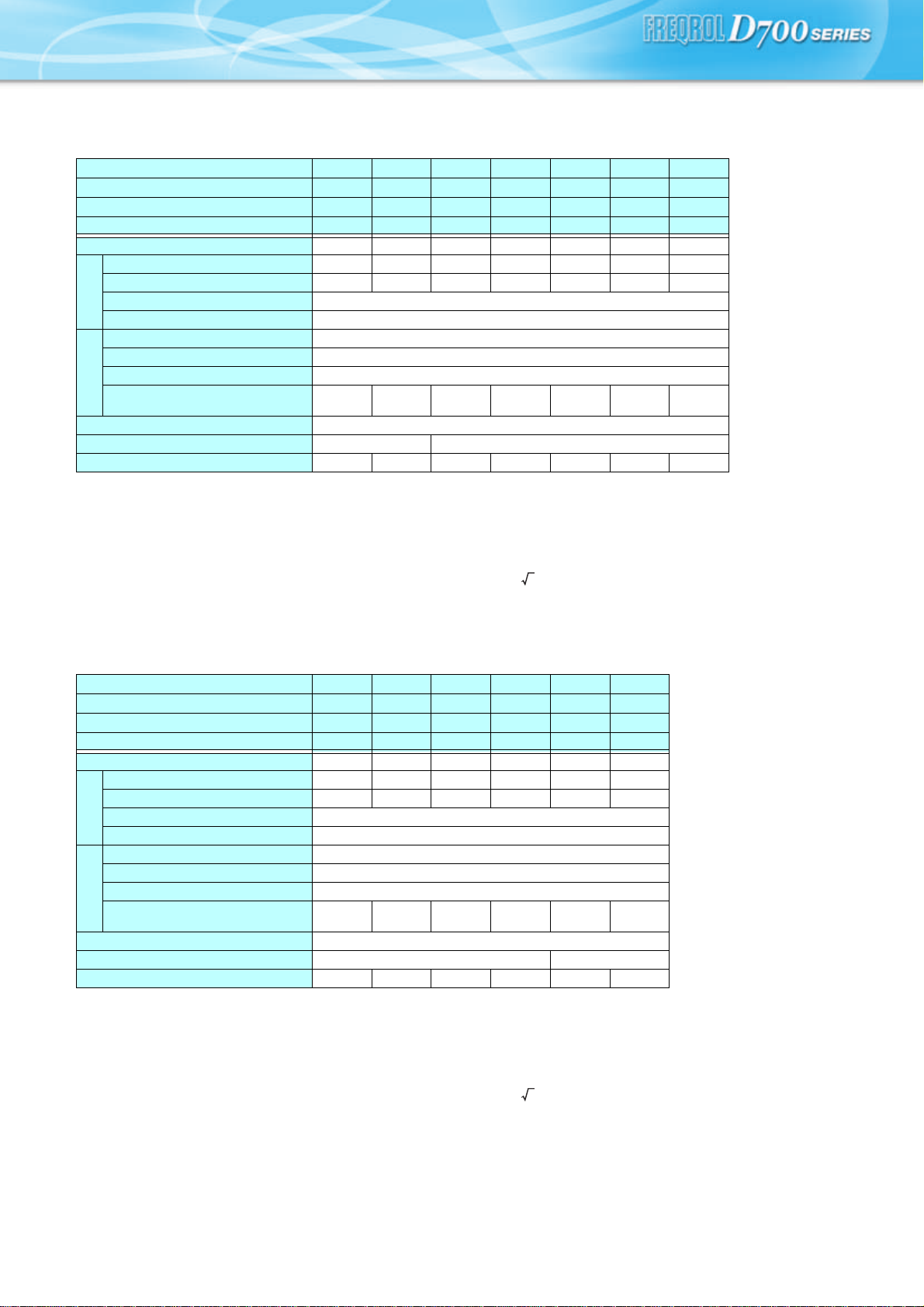
Standard specifications
Rating
z Three-phase 400V power supply
∗1 The applicable motor capacity indicated is the maximum capacity applicable for use of the Mitsubishi 4-pole standard motor.
∗2 The rated output capacity indicated assumes that the output voltage is 440V.
∗3 The % value of the overload current rating indicated is the ratio of the overload current to the inverter's rated output current. For repeated duty, allow time for
the inverter and motor to return to or below the temperatures under 100% load.
∗4 The maximum output voltage does not exceed the power supply voltage. The maximum output voltage can be changed within the setting range. However,
the pulse voltage value of the inverter output side voltage remains unchanged at about that of the power supply.
∗5 The power supply capacity varies with the value of the power supply side inverter impedance (including those of the input reactor and cables).
∗6 Totally enclosed structure series ends with -C.
z Single-phase 200V power supply
∗1 The applicable motor capacity indicated is the maximum capacity applicable for use of the Mitsubishi 4-pole standard motor.
∗2 The rated output capacity indicated assumes that the output voltage is 230V.
∗3 The % value of the overload current rating indicated is the ratio of the overload current to the inverter's rated output current. For repeated duty, allow time for
the inverter and motor to return to or below the temperatures under 100% load.
∗4 The maximum output voltage does not exceed the power supply voltage. The maximum output voltage can be changed within the setting range. However,
the pulse voltage value of the inverter output side voltage remains unchanged at about that of the power supply.
∗5 The power supply capacity varies with the value of the power supply side inverter impedance (including those of the input reactor and cables).
Model FR-D740-K(-C)∗6 0.4 0.75 1.5 2.2 3.7 5.5 7.5
Model FR-D740--NA 012 022 036 050 080 120 160
Model FR-D740--EC 012 022 036 050 080 120 160
Model FR-D740-K-CHT 0.4 0.75 1.5 2.2 3.7 5.5 7.5
Applicable motor capacity (kW)∗1 0.4 0.75 1.5 2.2 3.7 5.5 7.5
Output
Rated capacity (kVA)∗2 1.2 2.0 3.0 4.6 7.2 9.1 13.0
Rated current (A) 1.2 2.2 3.6 5.0 8.0 12.0 16.0
Overload current rating∗3 150% 60s, 200% 0.5s (inverse-time characteristics)
Voltage∗4 Three-phase 380 to 480V
Power supply
Rated input voltage/frequency Three-phase 380 to 480V 50Hz/60Hz
Permissible AC voltage fluctuation 325 to 528V 50Hz/60Hz
Permissible frequency fluctuation ±5%
Power supply capacity (kVA)∗5 1.52.54.55.59.512 17
Protective structure (JEM1030) Enclosed type (IP20). IP40 for totally enclosed structure series.
Cooling system Self-cooling Forced air cooling
Approximate mass (kg) 1.2 1.2 1.3 1.4 1.5 3.1 3.1
Model FR-D720S-K 0.1 0.2 0.4 0.75 1.5 2.2
Model FR-D720S--NA 008 014 025 042 070 100
Model FR-D720S--EC 008 014 025 042 070 100
Model FR-D720S-K-CHT 0.1 0.2 0.4 0.75 1.5 2.2
Applicable motor capacity (kW)∗1 0.1 0.2 0.4 0.75 1.5 2.2
Output
Rated capacity (kVA)∗2 0.3 0.5 1.0 1.6 2.8 3.8
Rated current (A) 0.8 1.4 2.5 4.2 7.0 10.0
Overload current rating∗3 150% 60s, 200% 0.5s (inverse-time characteristics)
Voltage∗4 Three-phase 200 to 240V
Power supply
Rated input voltage/frequency Single-phase 200 to 240V 50Hz/60Hz
Permissible AC voltage fluctuation 170 to 264V 50Hz/60Hz
Permissible frequency fluctuation ±5%
Power supply capacity (kVA)∗5 0.5 0.9 1.5 2.3 4.0 5.2
Protective structure (JEM1030) Enclosed type (IP20).
Cooling system Self-cooling Forced air cooling
Approximate mass (kg) 0.5 0.6 0.9 1.1 1.5 1.9
2
2
FeaturesOptions
Standard
Specifications
Operation panel
Parameter unit
Parameter
List
Protective
Functions
Terminal Connection
Diagram
Terminal Specification
Explanation
Outline
Dimension
Drawings
Instructions
FR-D700 Series
Specification
Difference List
Warranty
International
FA Center
6
Common specifications
Control specifications
Control method
Soft-PWM control/high carrier frequency PWM control (V/F control, general-purpose magnetic flux vector control,
optimum excitation control can be selected)
Output frequency range
0.2 to 400Hz
Frequency setting
resolution
Analog input
0.06Hz/60Hz (terminal2, 4: 0 to 10V/10bit)
0.12Hz/60Hz (terminal2, 4: 0 to 5V/9bit)
0.06Hz/60Hz (terminal4: 0 to 20mA/10bit)
Digital input
0.01Hz
Frequency
accuracy
Analog input
Within ±1% of the max. output frequency (25°C ±10°C)
Digital input
Within 0.01% of the set output frequency
Voltage/frequency characteristics
Base frequency can be set from 0 to 400Hz
Constant torque/variable torque pattern can be selected
Starting torque
150% or more (at 1Hz)...when general-purpose magnetic flux vector control and slip compensation is set
Torque boost
Manual torque boost
Acceleration/deceleration time setting
0.1 to 3600s (acceleration and deceleration can be set individually), linear or S-pattern acceleration/deceleration
mode can be selected.
DC injection brake
Operation frequency (0 to 120Hz), operation time (0 to 10s), operation voltage (0 to 30%) variable
Stall prevention operation level
Operation current level can be set (0 to 200% adjustable), whether to use the function or not can be selected
Operation specifications
Frequency setting
signal
Analog input
Two po in ts
Terminal 2: 0 to 10V, 0 to 5V can be selected
Terminal 4: 0 to 10V, 0 to 5V, 4 to 20mA can be selected
Digital input
Entered from operation panel and parameter unit. Frequency setting increments is selectable
Start signal
Forward and reverse rotation or start signal automatic self-holding input (3-wire input) can be selected.
Input signal
Five points
You can select from among multi-speed selection, remote setting, second function selection, terminal 4 input
selection, JOG operation selection, PID control valid terminal, external thermal input, PU-external operation
switchover, V/F switchover, output stop, start self-holding selection, traverse function selectiom, forward rotation,
reverse rotation command, inverter reset, PU-NET operation switchover, external-NET operation switchover,
command source switchover, inverter operation enable signal, and PU operation external interlock
Operational functions
Maximum/minimum frequency setting, frequency jump operation, external thermal relay input selection, automatic
restart after instantaneous power failure operation, forward/reverse rotation prevention, remote setting, second
function, multi-speed operation, regeneration avoidance, slip compensation, operation mode selection, offline
auto tuning function, PID control, computer link operation (RS-485), optimum excitation control, power failure
stop, speed smoothing control, Modbus-RTU
Output signal
Output signal
points
Open collector
output
One point
Relay output
One point
Operating status
You can select from among inverter operation, up-to-frequency, overload alarm, output frequency detection,
regenerative brake prealarm, electronic thermal relay function prealarm, inverter operation ready, output current
detection, zero current detection, PID lower limit, PID upper limit, PID forward/reverse rotation output, fan
alarm∗2, heatsink overheat pre-alarm, deceleration at an instantaneous power failure, PID control activated, PID
output interruption, during retry, life alarm, current average value monitor, remote output, alarm output, fault
output, fault output 3, and maintenance timer alarm
For meter
Output points
Pulse output
MAX 2.4kHz: one point
For meter
You can select from among output frequency, motor current (steady), output voltage, frequency setting, converter
output voltage, regenerative brake duty, electronic thermal relay function load factor, output current peak value,
converter output voltage peak value, reference voltage output, motor load factor, PID set point, PID measured
value, output power, PID deviation, Motor thermal load factor, Inverter thermal load factor
Pulse train output (1440 pulses/s/full scale)
Indication
Operation panel
Parameter unit
(FR-PU07)
Operating status
You can select from among output frequency, motor current (steady), output voltage, frequency setting,
cumulative energization time, actual operation time, converter output voltage, regenerative brake duty, electronic
thermal relay function load factor, output current peak value, converter output voltage peak value, motor load
factor, PID set point, PID measured value, PID deviation, inverter I/O terminal monitor, output power, cumulative
power, motor thermal load factor, inverter thermal load factor, PTC thermistor resistance.
Fault definition
Fault definition is displayed when the fault occurs and the past 8 fault definitions (output voltage/current/
frequency/cumulative energization time right before the fault occurs) are stored
Additional display
by the parameter
unit (FR-PU04/FR-
PU07) only
Operating status
Not used
Fault definition
Output voltage/current/frequency/cumulative energization time immediately before the fault occurs
Interactive
guidance
Function (help) for operation guide
Protective/warning function
<Protective functions>
Overcurrent during acceleration, overcurrent during constant speed, overcurrent during deceleration, overvoltage
during acceleration, overvoltage during constant speed, overvoltage during deceleration, inverter protection
thermal operation, motor protection thermal operation, heatsink overheat, input phase failure ∗4 ∗5, output side
earth (ground) fault overcurrent at start∗4, output phase failure, external thermal relay operation ∗4, PTC
thermistor operation∗4, parameter error, PU disconnection, retry count excess ∗4, CPU fault, brake transistor
alarm, inrush resistance overheat, analog input error, stall prevention operation, output current detection value
exceeded
<Warning functions>
Fan alarm∗2, overcurrent stall prevention, overvoltage stall prevention, PU stop, parameter write error,
regenerative brake prealarm ∗4, electronic thermal relay function prealarm, maintenance output ∗4, undervoltage,
operation panel lock, password locked, inverter reset
Environment
Surrounding air temperature
-10°C to +50°C (non-freezing) (-10°C to +40°C for totally-enclosed structure feature) ∗3
Ambient humidity
90%RH maximum (non-condensing)
Storage temperature∗1
-20°C to +65°C
Atmosphere
Indoors (without corrosive gas, flammable gas, oil mist, dust and dirt etc.)
Altitude/vibration
Maximum 1000m above sea level, 5.9m/s
2
or less
∗1 Temperatures applicable for a short time, e.g. in transit.
∗2 As the 0.75K or less is not provided with the cooling fan, this alarm does not function.
∗3 When using the inverters at the surrounding air temperature of 40°C or less, the inverters can be installed closely attached (0cm clearance).
∗4 This protective function does not function in the initial status.
∗5 This protective function is available with the three-phase power input specification model only.
7
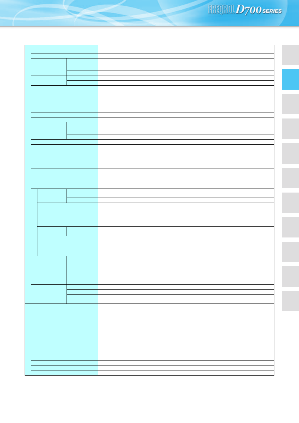
zFR-D720S-0.1K to 0.75K
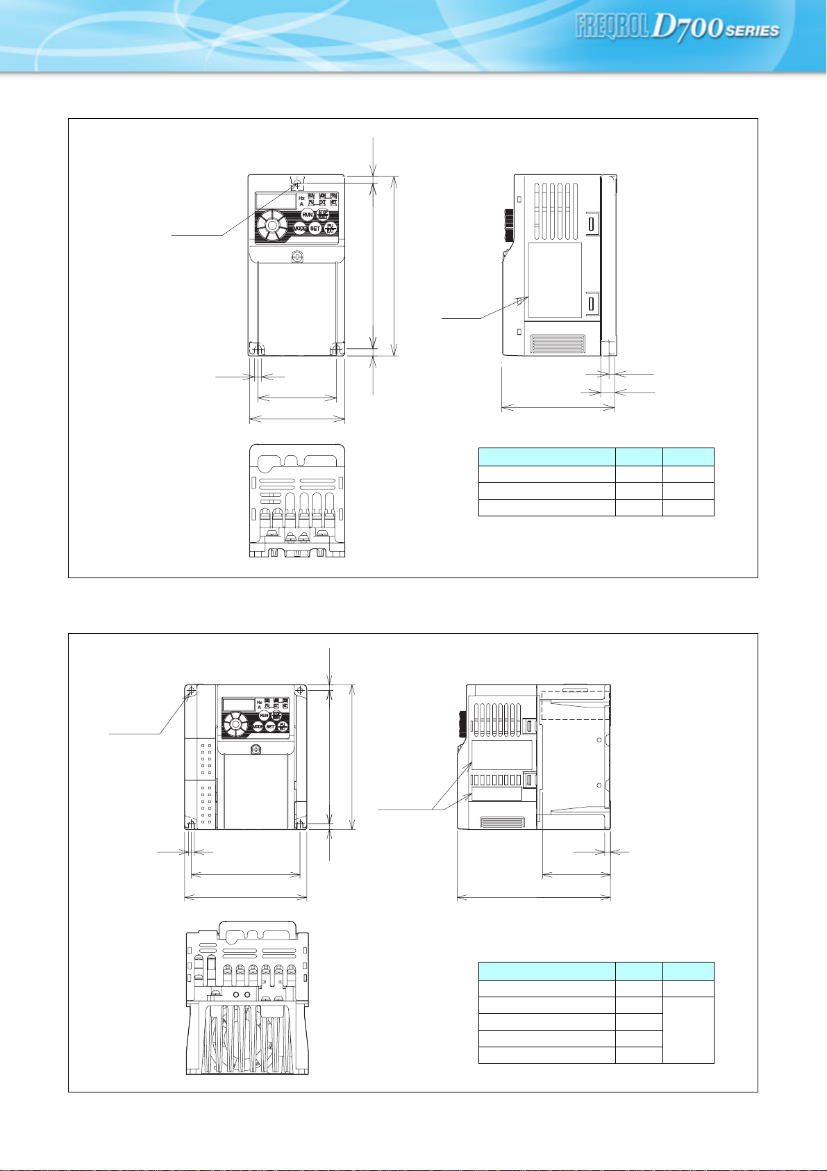
zFR-D740-0.4K to 3.7K
zFR-D720S-1.5K
(Unit: mm)
(Unit: mm)
1-φ5 hole
5
68
56
5 118 5
128
Rating
plate
D
4
D1
Inverter Type
D D1
FR-D720S-0.1K, 0.2K 80.5 10
FR-D720S-0.4K 142.5 42
FR-D720S-0.75K 162.5 62
Rating
plate
2-φ5 hole
*
FAN
5
96
108
5 5
128
118
5
D1
D
Inverter Type
D D1
FR-D740-0.4K, 0.75K 129.5 54
FR-D740-1.5K 135.5
60
FR-D740-2.2K 155.5
FR-D740-3.7K 165.5
FR-D720S-1.5K 155.5
∗ FR-D740-0.4K, 0.75K are not provided with the cooling fan.
Outline Dimension Drawings
FeaturesOptions
Standard
Specifications
Operation panel
Parameter unit
Parameter
List
Protective
Functions
Terminal Connection
Diagram
Terminal Specification
Explanation
Outline
Dimension
Drawings
Instructions
FR-D700 Series
Specification
Difference List
Warranty
International
FA Center
8
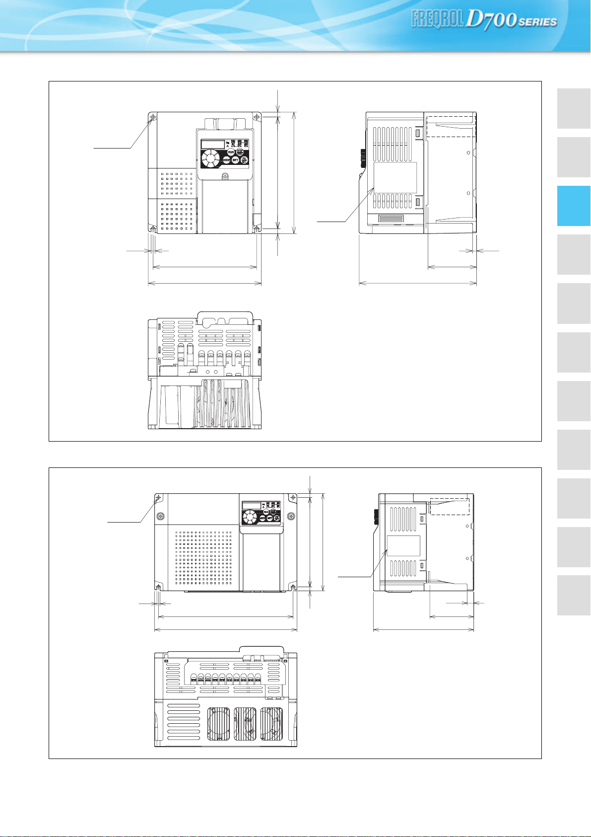
zFR-D720S-2.2K
zFR-D740-5.5K, 7.5K
(Unit: mm)
(Unit: mm)
2-φ5 hole
Rating
plate
128
140
5
138 66
150
FAN
5
60
145
2-φ5 hole
Rating
plate
6
1386
150
208
5
220
10
68
155
FAN
9
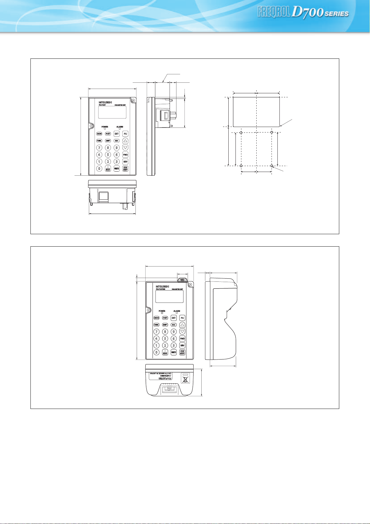
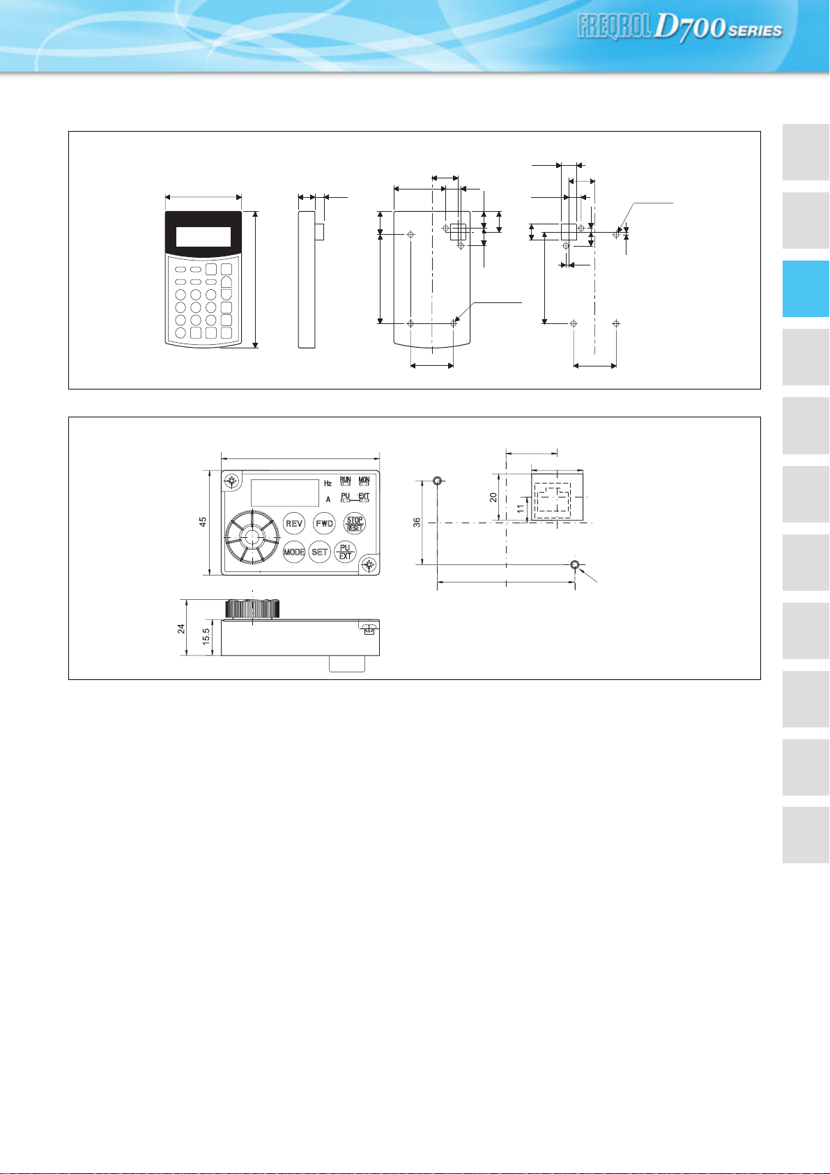
zParameter unit (option) (FR-PU07)
<Outline drawing> <Panel cut dimension drawing>
z
Parameter unit (option) (FR-PU07BB (-L))
<
Outline drawing>
67
51
40
56.8
57.8
26.5
4-R1
26.5
40
4-φ4 hole
(
Effective depth of the
installation screw hole 5.0)
M3 screw *2
Air-bleeding
hole
80.3
(14.2)
2.5
50
(11.45)
25.05
135
83
*1
*1
*1
*1
∗1 When installing the FR-PU07 on the enclosure, etc., remove screws or fix the screws to the FR-PU07 with M3 nuts.
∗2 Select the installation screw whose length will not exceed the effective depth of the installation screw hole.
(Unit: mm)
46.7
135
83
18
6
8.2
46.7
44.7
∗ Select the installation screw whose length will not exceed the effective depth of the installation screw hole.
(Unit: mm)
FeaturesOptions
Standard
Specifications
Operation panel
Parameter unit
Parameter
List
Protective
Functions
Terminal Connection
Diagram
Terminal Specification
Explanation
Outline
Dimension
Drawings
Instructions
FR-D700 Series
Specification
Difference List
Warranty
International
FA Center
10
zParameter unit (option) (FR-PU04)
<
Outline drawing><Panel cut dimension drawing>
zEnclosure surface operation panel (option) (FR-PA07)
<
Outline drawing><Panel cut dimension drawing>
40
5-φ4 hole
23.75
11.75
81.5
1.25
1.5
13
17
16.5
1.5
125
72 15 10.5
18.5
40
80
48
5-M3 screw
24
13
20
21.5
14.5
Effective
depth
of the
installation
screw hole
4.5
Select the installation screws whose length will not exceed the effective depth of the installation screw hole.
(Unit: mm)
68
59
22
22
2-M3 scre
w
(Unit: mm)
11
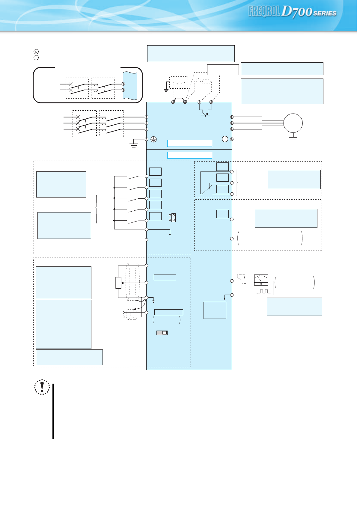
Terminal Connection Diagram
Note
y To prevent a malfunction caused by noise, separate the signal cables more than 10cm from the power cables.
y After wiring, wire offcuts must not be left in the inverter.
Wire offcuts can cause an alarm, failure or malfunction. Always keep the inverter clean. When drilling mounting holes
in an enclosure etc., take care not to allow chips and other foreign matter to enter the inverter.
y To ensure safety, for single-phase power input specification model, connect the power input to the inverter via a
magnetic contactor and earth leakage circuit breaker or moulded case circuit breaker, and use the magnetic
contactor to switch power on-off.
y The output of the single-phase power input specification is three-phase 200V.
Earth
(Ground)
Motor
IM
Earth (Ground)
Three-phase
AC power
supply
MCCB MC
R/L1
P1 P/+
PR
N/-
S/L2
T/L3
U
V
W
Earth
(Ground)
*7 Brake resistor (FR-ABR, MRS)
Install a thermal relay to prevent an
overheat and burnout of the brake resistor.
(The brake resistor can not be connected
to the FR-D720S-0.1K and 0.2K.)
Forward
rotation start
Reverse
rotation start
Middle
speed
High
speed
Low
speed
Control input signals (No voltage input allowed)
Contact input common
24VDC power supply
Contact input common
(Common for external power supply transistor)
STR
STF
RH
RM
RL
SD
PC
Relay output
Running
Open collector output
Open collector output common
Sink/source common
RUN
SE
A
B
C
Frequency setting signals (Analog)
2 0 to 5VDC
10(+5V)
2
3
1
4 4 to 20mADC
Frequency
setting
potentiometer
1/2W1kΩ
Terminal 4
input
(Current
input)
(+)
(-)
5(Analog common)
*5 It is recommended to use 2W1kΩ
when the frequency setting signal
is changed frequently.
*5
*2 When using terminals PC-
SD as a 24VDC power
supply, take care not to
short across terminals
PC-SD.
PU
connector
*1. DC reactor (FR-HEL)
When connecting a DC reactor, remove the
jumper across P1-P/+
Control circuit terminal
Main circuit terminal
Source logic
Jumper
*1
*7
*6
*2
*3
*4
Terminal functions vary
with the input terminal
assignment (Pr. 178 to
Pr. 182)
Multi-speed selection
Terminal functions vary by
Pr. 190 RUN terminal function
selection
Terminal functions vary
by Pr. 192 A,B,C terminal
function selection
SINK
SOURCE
VI
*4
0 to 5VDC
(0 to 10VDC)
0 to 10VDC
*4 Terminal input
specifications can be
changed by analog input
specifications switchover
(Pr. 267). Set the
voltage/current input
switch in the "V" position
to select voltage input (0
to 5V/0 to10V) and "I"
(initial value) to select
current input (4 to 20mA).
Voltage/current
input switch
Main circuit
Control circuit
R
Relay output
(Fault output)
Brake unit
(Option)
FM
SD
Indicator
(Frequency meter, etc.)
+
-
Moving-coil type
1mA full-scale
Calibration resistor
*8 It is not necessary when
calibrating the indicator
from the operation panel.
*8
Single-phase
AC power
supply
MCCB MC
R/L1
S/L2
Single-phase power input
*6 A brake transistor is not built-in to the
FR-D720S-0.1K and 0.2K.
*3 Terminal input specifications
can be changed by analog
input specifications
switchover (Pr. 73).
Terminal 10 and terminal 2
are used as PTC input
terminal (Pr. 561).
Loading...