


G Operating Instruction |
MIG/MAG 140 |
Welding machine |
MIG/MAG 160 |
|
FInstructions d'utilisation L’appareil de soudage sous gaz protecteur
NBruksanvisning Dekkgass-sveiseapparatet
JKäyttökäsikirja
Parhaat onnittelumme tämän korkealaatuisen
SBruksanvisning skyddsgassvets
115 164 4534 GB/F/N/SF/S 2508 2.1

G
F
N
J
S
Great Britain
France
Norge
Suomi/ Finland
Sverige
Retain proof of purchase! You are only entitled to claim warranty against proof of purchase.
Conservez le reçu d'achat! La garantie ne peut être accordée que sur présentation de ce reçu.
Oppbevar kvitteringen!
Garantiytelser skjer kun på grunnlag av forelagt kvittering.
Säilytä ostokuitti!
Takuu on voimassa vain kuittia vastaan.
Förvara kvittot!
Garantianspråk erkännes endast mot uppvisande av kvitto.
1.
2.
3.
4.
5.

Operation elements
1
2
3
4
5
1Connection for torch (+) pole
2Switch on/off and welding currant
3Wire feed regulator
4Overload control light
5Connection for earth clamp (–) pole
Dear customer,
Congratulations to your purchase of this high-quality MIG/MAG welding machine.
To ensure your personal safety and for reasons of appliance safety we ask you to read the instructions completely before operating this machine and to observe all points.
Basic Information for the Operator
The MIG/MAG welding machine is a DC welding power source with integrated wire feed, designed and manufactured exclusively for MIG and MAG electric arc welding.
Any other use of this machine involves dangers and is not permitted.
The welding machine must only be operated on the mains voltage stated on the machine's rating plate. Connection to the supply circuit must be made via an earthed outlet, installed by a qualified electrician. The supply circuit must be protected by a fuse or miniature circuit breaker.
Depending on the mains connection conditions at the point of connection, welding power sources can
MIG/MAG 140/160
cause disturbances to other consumers in the distribution system. Check with your power utility before connecting to power. (Class A in accordance with CISPR 11)
Keep the welding machine out of the reach of children.
Please note the hazards associated with the welding process and observe any work and fire prevention regulations.
The welding machine is not suitable for outdoor use in rain. Store in a dry place.
The unit is not suitable for unfreezing pipes.
ADanger!person with a heart condition wearing a pace maker must contact their doctor before operating this welding machine.
Safety Information and Accident
Prevention Measures
ξKeep the welding machine out of the reach of children.
ξObserve all applicable work and fire prevention regulations when operating this welding machine. Observe all applicable accident prevention regulations.
ξWith welding a number of different hazards are associated, which can pose a danger to health under certain circumstances.
ξWhen welding always wear a close fitting, dry overall (preferably fire retardant welders apparel) unsoiled by combustible substances, sturdy, insulating boots, headgear and leather welders gloves.
ξClothing made of synthetic fabrics and shoes are not suitable.
Dry, insulating gloves worn on both hands protect against electric shock (open-circuit voltage of the welding current circuit), hazardous rays (heat and ultra-violet rays) as well as against glowing metals and slag spatters. The ultra-vio- let radiation causes sunburn-like effects on unprotected parts of the body.
Fumes – Vapours – Smoke
ξDuring welding hazardous smoke and metal dust develops. We strongly recommend the wearing of welding fume respirators, and to weld only in sufficiently vented rooms, to ensure the necessary operator protection.
ξFor enclosed spaces forced ventilation, installed below the welding area, must be used.
ξThe material to be welded must be free from halogen solvents or degreasing agents, to prevent the generation of toxic vapours.
1.1

ξMetals coated with lead, graphite, cadmium, zinc, mercury or beryllium, or containing any of these materials, can generate much smoke during welding.
ξWelding releases ozone, which is a type of oxygen that can lead to irritation or disorder of the respiratory organs.
ξDegreasing agents such as trichlorethylene, tetrachloroethylene etc. vaporise during welding and are chemically converted into phosgene. Phosgene is poisonous!
UV-Rays
ξThe arc radiation can cause eye damage and skin burns.
ξFor protection against sparks, heat, visible and invisible rays suitable eye protection gear (welding visor or helmet with standardised filter lenses to class 10 – 15 of DIN 4647, depending on welding current) must be worn.
ξDo not look into the arc with unprotected eyes (risk of blinding and burns). The invisible ultraviolet radiation causes, with insufficient eye protection, a very painful conjunctivitis, which appears only hours later.
ξWeld only within the range of visibility of other persons, who can assist you in an emergency.
ξOther persons or helpers near the arc must be made aware of the hazards, and equipped with the necessary protective gear.
ξNeighbouring workplaces are to be screened off to provide protection against radiation.
ξWhen welding inside rooms and buildings sufficient ventilation must be ensured.
Fire
ADanger!The arc temperature is approx. 2400 °C.
Before starting to weld observe the following information:
ξRemove all combustible materials and objects within a radius of 5 m from the welding point.
ξMaterials that can not be removed within a 5 m radius must be protected by covering with sheet metal, wet cloths etc.
ξAny wall openings, cracks and the like must be covered or sealed respectively, to prevent uncontrolled flying of sparks.
ξKeep fire extinguishing equipment such as fire extinguisher, water pale etc. at hand.
ξKeep in mind that by heat dissipation from the welding point a fire may be started on covered parts or in other rooms respectively.
ξAfter completion of the welding work check the vicinity of the welding point several times within
1.2
a period of 6 – 8 hours for heat conduction, glowing combustion spots, hidden seats of fire etc.
Handling of Shielding Gas Cylinders
ξObserve all applicable regulations pertaining to the handling of gas cylinders. Because of the dangerously high internal pressure (up to 200 bar) shielding gas cylinders are to be specially protected against mechanical damage, falling over or falling down, heating up (max. 50°C), prolonged radiation by sunlight and heavy frost.
ξWhen the welding machine is equipped with a gas cylinder too large in size this can cause, on uneven ground, the welding machine to fall over. To prevent subsequent damage to the welding machine or the gas cylinder, use only proper size gas cylinders (10l / 20l cylinders).
ξHave cylinders refilled only by authorised filling stations.
Electrical Hazards
ξThe connection to power mains and servicing of the welding machine is to be done in accordance with VDE regulations or other standards applicable in your area.
ξEnsure proper protective bonding of the supply circuit.
ξEnsure proper protective bonding of the workbench.
ξAny service or maintenance work must only be carried out by qualified personnel.
ξReplace defective or damaged parts of torch or torch leads without delay.
ξThe unit must only be connected to an earthed outlet as a matter of principle. Only connections, including outlets and extension cables with an earthed plug, having an earth conductor and installed by a qualified electrician, are permitted.
ξThe fuse protection of the supply circuit must be in accordance with local regulations. According to these regulations fuses or miniature circuit breakers respectively, suitable for the conductor cross section, must be installed. Installation of a fuse with to high an ampere rating may cause line fire and subsequent fire damage to the building.
ξReplace damaged torch insulation and welding cables without delay.
ξReplacement of a damaged power cable, plug etc. and repairs to the electrical components of the welding machine must be left to a qualified electrician.
ξWelding torches must not be held in an armlock, or in such way that electricity can run through the body.
MIG/MAG 140/160

ξSwitch the unit off for longer work breaks. Unplug when work is completed and before relocating the unit. In case of accidents separate the welding power source at once from the power supply.
General Machine Description
The MIG/MAG welding machine consists of a transformer (static characteristic curve), a series-con- nected silicon rectifier, a welding circuit choke, and a wire feed unit.
The welding machine is suitable for the welding of different electrode wires (e.g. steel, see "Technical Specifications") under a shielding gas cover (CO2, mixed gas and argon).
The machine is fan cooled and has an overload protection.
Symbols Used
Danger!
Disregard of the following warnings could cause serious personal injury or material damage.
Read operating instructions before initial operation
Wire feed speed
Do not use in rain.
Welding machine suitable for welding in environments with an increased electrical hazard.
Excess temperaturer
Information on the name plate:
6 |
7 |
8 |
9 |
10 |
|
|
13 |
12 |
11 |
MIG/MAG 140/160 |
|
|
|
|
6Manufacturer
7 Machine designation
8Serial number
9Standard information – This machine meets the requirements of the standards mentioned
10CE mark – This machine conforms to EC directives as per declaration of conformity
11Waste disposal symbol – the machine can be disposed of through the manufacturer
12Electrical performance data
13Date of manufacture
Commissioning
Taking out of enclosed parts
All enclosed parts are inside the wire feed compartment and can be taken out after the wire feed compartment cover is removed..
Installation Conditions
ξThe protective gas welding unit must be installed in a dry environment with sufficient room for cooling.
ξIf the unit is placed on an inclined surface it must be secured against falling: place the unit on a suitable level support surface.
ξThe unit is designed for use in covered areas. Welding outside in the rain is not permitted.
Mains connection
ξCheck to see that mains voltage matches the voltage shown on the machine's rating plate.
ξSet welding step switch to "0" before plugging in.
Shielding gas cylinder connection
ξPlace gas cylinder onto the welding machine's cylinder rack and secure with the chain to the cylinder holder at the rear of the unit. Take off the cylinder cap and open cylinder valve briefly, facing away from your body.
ξScrew pressure reducer to the gas cylinder valve. Run gas hose from pressure reducer to gas inlet port of the unit.
ξRecommended gas flow rate in draft-free rooms: 5-10 l/min.
1.3

ξWhen using adjustable pressure reducers set flow rate according to litre scale in the clock with the T-screw. Turning the T-screw in increases the gas flow rate, turning it out reduces the gas flow rate.
ξWhile setting the gas flow rate, the unit must be switched on and the torch's trigger switch held down, so the solenoid gas valve is open. To prevent wasting electrode wire swing the wire feed unit's leaf spring to the side.
Modifications and repairs to pressure reducers are strictly prohibited due to the hazards involved. Send faulty pressure reducers to a service centre.
Earth lead connection
Connect earth clamp of the unit's earth cable as close as possible to the welding point. Ensure good metal to metal contact.
Preparation of the welds
The joint section of the workpieces to be welded must be free of colour, metall covering, dirt, rust, grease and humidity.
The preparation of the welds is to be done under observation of all welding techniques regulations.
Hints for Setting and Welding Techniques
Switching the unit on
The unit is switched on with the combination ON/ OFF – welding step switch. With the switch in the "0"- position the unit is electrically separated from the power supply.
The unit is fitted with an embedded temperature detector, which shuts the unit down in case of an thermal overload.
The tripping of the thermal overload protector is indicated by the front panel control light. Welding power source and wire feed are temporarily disabled.
After cooling down the welding power source is automatically activated again, the control light extinguishes.
Setting the welding parameters
After preparation of the welding machine the welding can begin.
To do so, welding voltage and wire feed have to be matched to suit the welding task. If the wire feed speed is increased the welding current increases accordingly.
For every electrode wire diameter and every welding task optimal parameters can be found. They are recognisable at the typical humming sound of the arc, amongst other.
If there is too much deviation from the optimal parameters, a satisfactory welding is not possible.
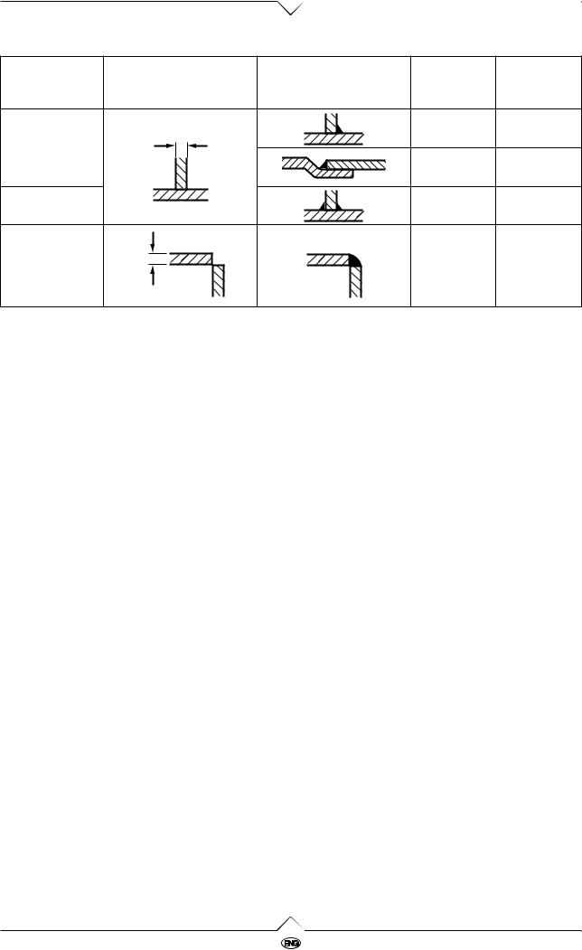
The right joint
The list gives hints for the shaping of the joints.
|
|
|
|
Platethick- |
Gapwidth |
|
Form of joint |
Execution |
ness |
||
|
b (mm) |
||||
|
|
|
|
s (mm) |
|
|
|
|
|
|
|
I-joint onesided |
|
s |
|
< 1,5 |
0 |
|
|
|
> 1,5 |
< 2 |
|
|
|
|
|
||
I-joint on both |
|
b |
|
2 – 4 |
< 2 |
sides |
|
|
|||
|
|
|
|
|
|
V-joint |
2 |
5 |
|
3 – 6 |
< 1 |
|
|
||||
|
|
s |
|
||
|
|
|
|
|
|
|
|
b |
|
3 – 6 |
< 1 |
|
|
|
|
|
|
1.4 |
MIG/MAG 140/160 |
|
|
Platethick- |
Gapwidth |
|
Form of joint |
Execution |
ness |
||
b (mm) |
||||
|
|
s (mm) |
||
|
|
|
||
K-joint |
|
> 0,6 |
– |
|
s |
|
|||
|
|
|
||
|
|
0,6 – 1,5 |
– |
|
Double-K-joint |
|
> 0,6 |
– |
|
|
|
|||
Cornerjoint |
|
> 1 |
– |
|
|
|
s
Care and Maintenance
The unit is nearly maintenance-free.
BDanger – Voltage!
Disconnect from power before servicing!
ξCheck feed roller, pressure roller and wire leadin nozzle at regular intervals for dirt build-up, clean if necessary.
ξAt appropriate intervals the complete torch including torch leads should be cleaned, as rubbed-off parts and dust build-up inside.
ξThe torch's contact tip is a wearing part. If its orifice has enlarged the contact tip must be replaced.
ξOn the inside of the plug-on gas shroud spatters build up. These have to be removed when necessary. An anti-spatter spray eases this job and keeps spatters from sticking to the shroud.
ξReplace damaged cables without delay.
Trouble Shooting
Mechanical faults are mostly indicated by an irregular or completely blocked wire feed. Electrical faults cause a malfunction of the unit, in part or complete.
BDanger - Voltage!
Electrical fault finding must be left to a qualified electrician.
Further fault finding can proceed according to the wiring diagram supplied.
Fault find should first start with the unit de-ener- gized, and in the following order:
1.Check of the power supply cable connection and all other connections on switches, transformer and choke, as well as all plug-and-socket connections and soldered connections for tightness.
2.Check of fuse for continuity and contact.
3.Visual check for possible shorts or overloads of windings (discoloring).
Fault, Likely causes |
|
Remedy |
|
|
|
• Noisy or unstable arc? |
|
|
|
|
|
Incorrect welding volt- |
|
Correct with welding step |
age |
|
switch |
|
|
|
Too much/too little wire |
|
Correct with wire feed pot |
feed |
|
|
|
|
|
Earth clamp loose or |
|
Ensure good contact |
high contact resistance |
|
between earth clamp and |
(rust, paint) |
|
workpiece |
|
|
|
Contact tip worn or |
|
Replace |
incorrect diameter |
|
|
|
|
|
Incorrect gas flow rate |
|
Correct |
setting |
|
|
|
|
|
Workpiece not clean in |
|
Remove paint, rust, grease |
seam area |
|
etc. |
|
|
|
Power unit faulty |
|
Have machine checked by |
|
|
service centre |
|
|
|
Spiral liner dirty |
|
Clean or replace |
|
|
|
Wire feed faulty |
|
See below |
|
|
|
|
|
|
• Excessive spattering |
|
|
|
|
|
Wire feed rate too high |
|
Correct with wire feed pot |
|
|
|
Welding voltage too |
|
Correct with welding step |
high |
|
switch |
|
|
|
Workpiece not clean |
|
Clean |
|
|
|
MIG/MAG 140/160 |
1.5 |

• Wire feed motor does not run
No power |
Check power supply |
|
|
Welding step switch in |
Set to a welding step |
"0" position |
|
|
|
Torch trigger switch not |
Activate torch trigger switch |
activated |
|
|
|
Fuse blown |
Have replaced by a qualified |
|
electrician |
|
|
Motor faulty |
Have repaired by service |
|
centre |
|
|
• No wire feed
Pressure roller loose |
Increase pressure of leaf |
|
spring with knurled thumb |
|
screw |
|
|
Wire kinked at wire |
Adjust wire lead-in nozzle |
feed |
|
|
|
Groove in feed roller |
Replace |
worn |
|
|
|
Electrode wire stuck to |
Replace contact tip, if wire is |
contact tip |
deformed, reduce pressure |
|
of pressure roller |
|
|
|
|
• Machine shuts down, overload control light |
|
comes on |
|
|
|
Duty cycle exceeded |
Let machine cool down, |
|
observe duty cycle stated on |
|
nameplate |
|
|
Power unit faulty |
Have repaired by service |
|
centre. |
|
|
Technical Specification
|
MIG/MAG 140 |
MIG/MAG 160 |
|
|
|
Power supply |
1 x 230 V, 50/60 Hz |
1 x 230 V, 50/60 Hz |
|
|
|
Power input max. |
5,1 kVA |
5,3 kVA |
|
|
|
Current draw max. |
22 A |
23 A |
|
|
|
Mains fuse, time-lag |
16 A |
16 A |
|
|
|
Open-circuit voltage |
17,5 – 28 V |
19 – 30 V |
|
|
|
Welding current range |
30 – 140 A |
30 – 160 A |
|
|
|
max. Duty cycle (40°C) |
4 % |
8 % |
|
|
|
Welding steps |
4 |
4 |
|
|
|
Wire feed rate |
1,0 – 12 m/min |
1,0 – 12 m/min |
|
|
|
Electrode wire diameter |
0,6 – 0,8 mm |
0,6 – 0,8 mm |
|
|
|
Protection class |
IP 21 |
IP 21 |
|
|
|
Length x Width x Height |
590 x 260 x 420 mm |
590 x 260 x 420 mm |
|
|
|
Weight |
21 kg |
26,5 kg |
|
|
|
Current setting range
Position |
MIG / MAG 140 |
MIG / MAG 160 |
|
||||
|
|
|
|
||||
1 |
30 A |
30 A |
|
|
|
|
|
|
|
|
|
||||
2 |
50 A |
60 A |
|
|
|
|
|
|
|
|
|
||||
3 |
80 A |
100 A |
|
|
|
|
|
|
|
|
|
||||
4 |
140 A |
160 A |
|
|
|
|
|
|
|
|
|
|
|
|
|
|
|
|
|
|
|
|
|
1.6 |
|
|
|
|
|
|
MIG/MAG 140/160 |
|
|
|
|
|
|||
|
|
|
|
|
|
||
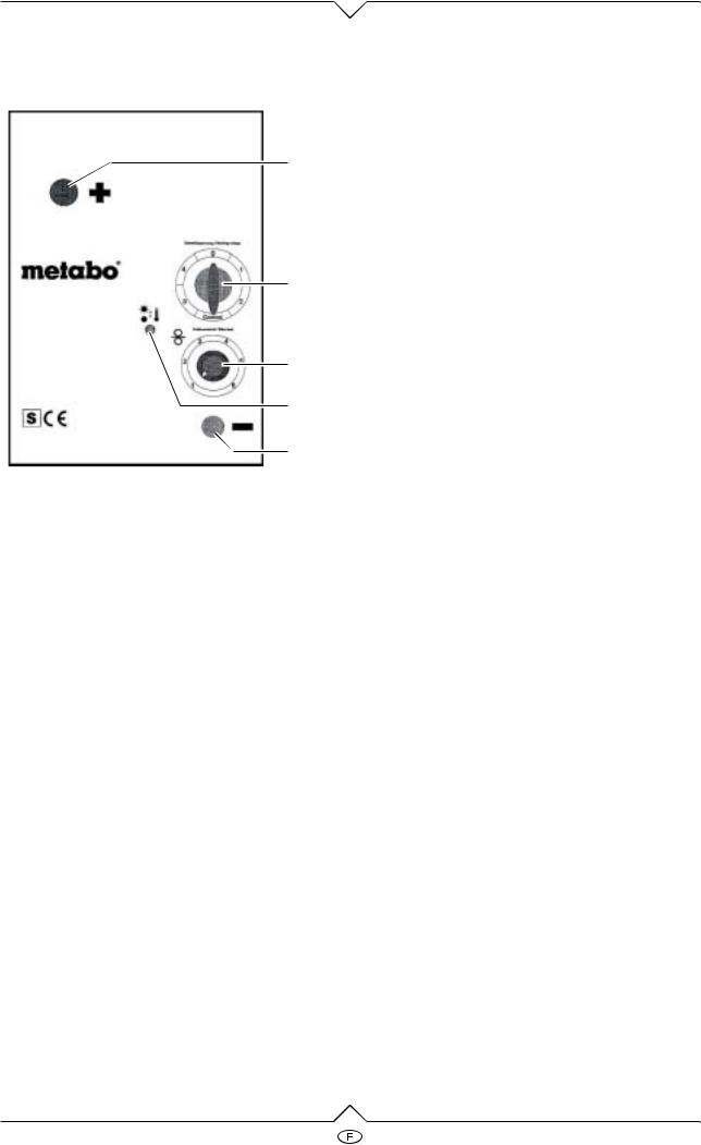
Eléments de commande
1
2
3
4
5
1Branchement chalumeau Pôle (+)
2Interrupteur marche/arrêt et courant de soudage
3Régulateur d’avancement du fil
4Indicateur de surcharge
5Branchement pince à électrodes à la masse Pôle (–)
Cher client, chère cliente,
nous vous félicitons d’avoir acheté cet appareil de soudage sous gaz protecteur de haute qualité. Afin de garantir votre sécurité et la sécurité de l’appareil, nous vous prions de bien vouloir lire complètement et consciencieusement ces instructions avant la mise en service, et de respecter ces instructions en tous points.
Conseils de principe pour l’utilisateur
L’appareil de soudage sous gaz protecteur MIG/ MAG est une source de courant continu avec avancement du fil intégré, conçue et construite uniquement pour le soudage à l’arc MIG, voire MAG. Toute autre utilisation de l’appareil est soumise à des risques et donc interdite.
L’appareil ne peut être mis en service que sous la tension secteur indiquée sur la plaque signalétique. Le branchement ne peut se faire qu’avec des prises de courant de sécurité, qui auront été installées par un spécialiste autorisé en électricité. Le circuit élec-
MIG/MAG 140/160
trique des prises de courant doit être protégé par fusibles ou par interrupteur automatique.
Selon les conditions de branchement sur secteur au point de jonction, les sources de courant de soudage peuvent entraîner des perturbations dans le secteur pour d’autres consommateurs. Pour résoudre ce problème et pour éviter de telles perturbations, il est nécessaire de se renseigner avant le branchement auprès de l’entreprise chargée de l’alimentation en courant. (Classe A selon CISPR 11)
Il faut tenir l’appareil hors de la portée des enfants. Tenez compte des risques que représentent les travaux de soudage et respectez le règlement du travail ainsi que les consignes de prévention d’incendie.
L’appareil doit être rangé à l’abri de l’humidité et n’est pas conçu pour être utilisé dehors, lorsqu’il pleut.
L'appareil ne convient pas au décongelage de tubes.
ADanger!Les personnes qui portent un stimulateur cardiaque doivent obligatoirement consulter leur médecin avant de travailler avec l’appareil à soudage!
Conseils de sécurité et mesures préventives contre les accidents
ξL’appareil à soudage sous gaz protecteur doit être tenu hors de la portée des enfants.
ξLorsque l’on travaille avec l’appareil à soudage sous gaz protecteur, il faut respecter le règlement du travail ainsi que les consignes de prévention d’incendie en vigueur. Il faut également respecter les instructions préventives en vigueur contre les accidents !
ξLors du soudage, différentes sortes de risques pourraient éventuellement causer des dommages à la santé.
ξLors du soudage, il faut porter une combinaison fermant hermétiquement, ne portant pas de traces de substances qui s’enflamment facilement, et sèche (mieux encore une combinaison pour soudeur très résistante aux flammes), des chaussures robustes, isolantes (bottes), une protection sur la tête et des gants à fourreau en cuir.
ξLes vêtements en matières synthétiques ainsi que les chaussures basses ne sont pas adéquats. Des gants isolants aux deux mains protègent des secousses électriques (tension à vide du circuit électrique de soudage), des radiations nocives (rayons thermiques et ultraviolets) de même que des éclaboussures de métal ardent et de laitier. La radiation ultraviolette a un effet semblable aux coups de soleil sur les parties du corps qui ne sont pas protégées.
2.1

Gaz – vapeurs – fumée
ξPendant le soudage, il y a formation de fumée nocive et de poussière de métal. Nous vous conseillons d’utiliser des masques de protection contre la fumée et de veiller à une alimentation suffisante d’air frais dans les locaux où s’effectue le soudage, afin de garantir la protection nécessaire du personnel.
ξDans des locaux fermés, il est absolument indispensable d’utiliser des exhausteurs qui devront être installés en-dessous de la zone de soudage.
ξLe matériel que l’on veut souder ne doit pas porter de traces de dégraissants à solution halogène, pour empêcher la formation de gaz toxiques.
ξLes métaux qui sont recouverts de plomb, de graphite, de cadmium, de zinc, de mercure ou de béryllium ou qui contiennent ces matériaux, sont susceptibles de dégager beaucoup de fumée au cours du soudage.
ξLors du soudage, il y a dégagement d’ozone. Il s’agit d’une sorte d’oxygène qui peut entraîner des irritations ainsi que des maladies des organes respiratoires.
ξLes produits solvants de graisse comme le trichloréthylène, le perchloréthylène, etc. s’évaporent pendant le soudage et se transforment, dû à une modification chimique, en gaz phosgène. Le gaz phogène est toxique!
Rayons ultraviolets
ξLes rayons de l’arc électrique peuvent provoquer des blessures aux yeux et des brûlures de la peau.
ξPour se protéger des étincelles, de la chaleur, des rayons visibles et invisibles, il faut porter des protections optiques adéquates (écran protecteur ou coiffe protectrice pourvus de verres de protection contre les rayons d’échelons 10 à 15 normés DIN 4647, selon la puissance électrique).
ξOn ne doit pas regarder l’arc électrique si les yeux ne sont pas protégés (risque d’éblouissement et de brûlure). Si la protection est insuffisante, la radiation ultraviolette invisible provoquera une conjonctivite douloureuse que l’on ne remarquera que quelques heures plus tard.
ξPour effectuer le soudage, il est nécessaire d’avoir à proximité des personnes qui pourront venir à l’aide immédiatement, en cas d’accident.
ξLes personnes ou les assistants qui sont à proximité de l’arc électrique doivent être informés des dangers existants et être équipés de la protection adéquate.
ξIl est nécessaire de protéger les places de travail environnantes de la radiation: installer les écrans de protection en conséquence.
ξLors de travaux de soudage dans des pièces et des bâtiments, il faut veiller à une bonne circulation de l’air.
Feu
ADanger!
La température de l’arc électrique s’élève
environ à 2400 °C.
Avant de commencer les travaux de soudage, veuillez suivre les conseils suivants:
ξDans un rayon de 5 m de l’endroit de soudure, il faut éloigner toutes les substances et les objets.
ξLes substances se trouvant dans un rayon de 5 m et qui ne peuvent pas être éloignées doivent être protégées correctement: on les recouvre de tôles d’acier, de linges mouillés, etc.
ξLes ouvertures, fentes, orifices dans les murs, etc., doivent être recouverts ou calfeutrés afin de les protéger des flammèches incontrôlées.
ξLes moyens d’extinction tels que les extincteurs de feu, les seaux à eau, etc., sont à tenir à disposition.
ξN’oubliez pas que, dû à la conduction de chaleur au point de soudure, un incendie peut se déclarer sur des objets recouverts ou dans d’autres pièces.
ξAprès avoir terminé les travaux de soudage, assurez-vous à plusieurs reprises dans les 6 – 8 heures qui suivent, qu’il ne reste pas d’endroits incandescents, de foyers ardents ou de conduction thermique aux environs de l’endroit où le soudage a eu lieu.
Maniement des bouteilles de gaz protecteur
ξPour le maniement des bouteilles de gaz protecteur, il faut respecter les consignes de sécurité en vigueur. Il faut tout particulièrement protéger les bouteilles de gaz protecteur, à cause de leur haute pression interne (jusqu’à 200 bar), des détériorations mécaniques, empêcher qu’elles ne basculent ou dégringolent. Il faut également empêcher qu’elles ne se réchauffent (max. 50 °C), ne soient exposées trop longtemps aux rayons du soleil ou à un gel extrême.
ξLorsque l’on équipe l’appareil MIG/MAG de la bouteille de gaz protecteur, il faut être conscient du fait que de trop grandes bouteilles, posées un sol inégal, peuvent faire basculer l’appareil. Pour éviter les dommages qui en résulteraient pour l’appareil, voire pour la bouteille de gaz, on ne doit utiliser que des bouteilles de taille convenable (bouteilles de 10 ou 20 litres).
2.2 |
MIG/MAG 140/160 |
 Loading...