


Assembly/Operating Instructions
Site Saw BKS 400/BKS 450
Model No. 1001
3305 |
Stock-no. 115 107 8059 |
Contents
1.0Scope of Application
2.0Specifications
3.0User Responsibility
4.0Standard Accessories
5.0Optional Accessories
6.0Assembly
7.0Mitre Fence Assembly
8.0Installation
9.0Operation/Settings
10.0 Cutting
11.0 Saw Dust Collection (optional accessory)
12.0 Crane Lifting
13.0 Safety Rules
14.0 Care and Maintenance
15.0 Wiring Diagrams
16.0 Spare Parts List and Drawing
1.0Scope of Application
-This site saw model BKS 400/BKS 450 has been designed to perform rip and cross cuts in wood having a square or rectangular cross section.
-Cross cuts should only be performed with the help of the mitre fence.
-Round stock or firewood should not be cut without an appropiate jig holding the work safely.
-The maximum/minimum blade diameters are 400/350 mm for model BKS 400 and 450/350 mm for model BKS 450.
2.0 Specifications
|
BKS 400/3.1 WNB |
BKS400/4.2 DNB |
BKS450/4.75DNB |
|
|
|
|
Table size |
1000 x 665 mm |
1000 x 665 mm |
1000 x 665 mm |
Table height from floor |
850 mm |
850 mm |
850 mm |
Depth of cut |
127 mm |
127 mm |
152 mm |
Motor speed 50/60 Hz |
2800/3360 rpm |
2800/3360 rpm |
2800/3360 rpm |
Cutting speed |
58.5 m/sec |
58.5 m/sec |
66 m/sec |
Motor capacity P1 S6 40% |
3.1 kW |
4.2 kW |
4,75 kW |
Motor capacity P2 S1 100% |
1.5 kW |
2.1 kW |
2.4 kW |
Voltage |
1~ 220/240V |
3~ 380/440V |
3~ 380/440V |
Mains fuse |
1 x 16A |
3 x 16A |
3 x 16A |
Max. saw blade diameter |
400 mm |
400 mm |
450 mm |
Min. saw blade diameter |
350 mm |
350 mm |
350 mm |
Saw blade bore |
30 mm dia. |
30 mm dia. |
30 mm dia. |
|
|
|
|
Note: Saw blade 450mm diameter requires 4.75kW motor. Use of 450mm blades with 3.1kW and 4.2kW motor voids factory warranty!
3.0 User Responsibility
This machine will perform in conformity with the description contained in the instructions provided. This machine must be checked periodically. Defective equipment (including service leads) should not be used. Parts that are broken, missing, plainly worn, distorted or contaminated, should be replaced immediately. Should such repair or replacement become necessary, it is recommended that such repairs are carried out by qualified persons approved by the equipment manufacturer or its representative. This machine or any of its parts should not be altered or changed from standard specifications. The user of this machine shall have the sole responsibility for any malfunction which results from improper repair by anyone other than qualified persons approved by the equipment manufacturer or its representatives.
Note
Within the U.K., this machine falls under the Woodworking Machinery Regulations 1974, under which certain operations, e.g. grooving, rebatting, tenoning and moulding are prohibited without special guards. For your own safety it is recommended to follow the instructions given in the Health and Safety at Work booklet No.41, entitled “Safety in the Use of Woodworking Machines” and “A Guide to Woodworking Machinery Regulations” HS(R)9. Both publications are available from Her Majesty’s Stationary Office and other bookshops.
The information contained in this manual is intended to make the operator of this saw familiar with its safety features, setting of guards and fences, and the safe performance of the different basic cutting operations normally carried out with this type of saw. It does not teach the operator how to become an expert woodworker. Those persons interesting in gaining a more intimate knowledge on the tasks which can be carried out on this type of saw are advised to refer to commercially available literature on the subject.
4.0 Standard Accessories
-Saw blade
-Riving knife DIN 38820 Gr. 50x3
-Saw blade guard
-Rip fence
-Mitre fence
-Lifting eyes
-Push stick
-Tool set
-Operating instructions
5.0 Optional Accessories
For the metabo Site Saws BKS the following accessories are available at extra cost:
- |
Sliding Carriage BKS/BKH |
Stock-no. 0910 00666 5 |
- |
Extension Table BKS/BKH |
Stock-no. 0910 00667 3 |
- |
Dust Extraction Adaptor BKS 100mm |
Stock-no. 0910 00874 9 |
- Log Cutting Attachment BKS/BKH |
Stock-no. 0910 00886 2 |
|
6.0 Assembly
Place table onto firm support (e.g. saw horses).
Attach table insert (aluminium extrusion) to table; use 10 pcs. countersunk flat-head screw 4.2x13. Bolt rip fence guide extrusion to front of table.
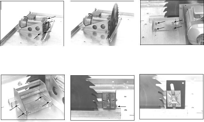
Bolt both support brackets to the motor. Use 4 each hex. head screw M8x16 hex. nut M8. Attach the thus preassembled motor to the table, but do not yet tighten fully. Use 4 each countersunk screw M8x16
hex.nut M8 washer 8.4
Install saw blade onto motor, than align motor so that the saw blade is centered in the table insert’s slot.
When positioned correctly fully tighten the motor on the table.
Attach mounting plate for the riving knife carrier bracket to the table.
Use 4 each
countersunk screw M6x16 hex. nut M6
Attach riving knife carrier bracket loosely to mounting plate.
Use 4 each
hex. head screw M6x16 washer 6.4
hex. nut M6
top
Place carriage bolt M12x30 into slot of carrier braand slide riving knife carrier onto bolt. The imprint “Oben” must point towards the table.
Mount riving knife and secure in place with pressure plate and self-locking hex. nut M12.
Align riving knife with saw blade, then fully tighten the screws ficing the riving knife carrier bracket to the mounting plate.

90°
Place both support struts onto the table, set square with the slot of the table insert and bolt to the table. Use 10 each
countersunk screw M6x16, hex. nut M6
Bolt switch to front support strut. Use 2 each hex. head bolt M6x16
torque type hex. nut M6
Install both hex. head bolts M8x90 into chipcase, secure with hex. nuts M8
Install the guard support bracket without fully tightening the screws.
Use 2 each
countersunk screw M6x16, hex. nut M6, hex. head screw M8x16,
hex. nut M8
Attach strain relief clamp to support strut. Use hex. head bolt M6x16
hex. nut M6
Re-install saw blade, be sure of correct direction of rotation. Install chip case lid. Use 2 each torque type hex. nut M8
Attach gusset plate with carriage bolt M10x25, washer 10.5 and starknob M10
Remove saw blade and bolt chip case to both support struts and motor plate. Hardware:
4 ea. hex head screw M8x16
4 ea. hex. nut M8
2 ea. hex. head bolt M6x16
2 ea. washer 6.4
2 ea. hex. nut M6
Bolt lifting eyes to table (at rear left and front right). Place pressure spring onto bolt before screwing on nut. Use 2 each
hex. bolt M8x35 pressure spring 9x20 torque type hex. nut M8
|
"A" |
Install legs with struts and diagonal struts to table. |
Turn saw over and stand onto its legs. |
- Tighten all screws handtight only at this stage. - Install struts as shown in drawing “A”. |
Align and fully tighten all screws. |
Hardware: 22 each hex. head bolt M8x16; 4 each hex. head bolt M8x20; 26 each hex. nut M8 |
|
 Loading...