


Bedienungsanleitung
 Operating Instructions
Instructions de service
Gebruiksaanwijzing
 Instrucciones de uso
Invert 130/40
Invert 130/60
115 162 4029 / 0803 - 3.2
Achtung! Lesen Sie diese Anleitung vor der Installation und Inbetriebnahme aufmerksam durch. Attention! Carefully read through these instructions prior to installation and commissioning. Attention! Prière de lire attentivement la présente notice avant l'installation et la mise en service. Attentie! Lees deze instructies voor de installatie en ingebruikname aandachtig door.
¡Atención! Lea con detenimiento estas instrucciones antes de la instalación y de la puesta en servicio.

ENG
Table of Contents
1 |
Technical Specifications |
6.1 |
Tips for TIG-Welding |
2 |
Scope of Application |
7 |
Overloads |
2.1 |
Information |
8 |
Trouble Shooting |
3 |
Commissioning |
9 |
Safety Information |
4 |
Description |
9.1 |
Protection against Electrical Accidents |
5 |
Operation |
10 |
Wiring Diagram |
6 |
TIG-Welding (optional) |
|
|
1 Technical Specifications
|
|
Invert 130/40 |
Invert 130/60 |
Mains voltage: |
|
1 ~ 230/240 V |
1 ~ 230/240 V |
Mains frequency: |
|
50 - 60 Hz |
50 - 60 Hz |
Setting range: |
|
100 V |
100 V |
Stromeinstellbereich: |
|
5 - 130 A |
5 - 130 A |
Power input: |
manual arc |
4.5 kVA |
4.85 kVA |
|
TIG |
3.1 kVA |
3.1 kVA |
Operating voltage: |
manual arc |
20,2 - 25,2 V |
20.2 - 25.2 V |
|
TIG |
10,2 - 15,2 V |
10.2 - 15.2 V |
Max. current draw: |
|
27 A |
27 A |
Mains fuse: |
|
16 A time-lag |
16 A time-lag |
Duty cycle at max. |
manual arc |
130 A / 50 % / 35 % |
130 A / 80 % / 55 % |
ouput (25 °C/ 40 °C): |
TIG |
130 A / 40 % / 30 % |
130 A / 60 % / 40 % |
Operating modes: |
|
manual arc/TIG |
manual arc/TIG |
Setting: |
|
stepless |
stepless |
Suitable electrodes |
manual arc |
from 1.5 mm Ø |
from 1.5 mm Ø |
|
TIG |
for steel 0.3 mm and up |
for steel 0.3 mm and up |
Protection class: |
|
IP 23 S |
IP 23 S |
Cooling: |
|
F |
F |
Insulation class: |
|
F |
F |
Temperature range: |
operation |
-10 °C - +40 °C |
-10 °C - +40 °C |
Dimensions ( l x w x h): |
|
255 x 110 x 210 mm |
235 x 110 x 220 mm |
Weight: |
|
4.9 kg |
4.9 kg |
Operating conditions: |
|
relative humidity 10-80 % |
relative humidity 10-80 % |
2 Scope of Application
The inverter welding machines are designed as a compact, easy to operate and field-safe unit. With it all metals (except aluminium) can be welded. Special consideration has been given to stick electrode welding capabilities, i.e. vertical-down welding. Due to its wide range of welding current setting the Invert 130 is very versatile, e.g. for sheet metal and steel welding. In addition there is the capability of TIG welding with scratch start. With this welding process steel, stainless steel and NF-metals (except aluminium) can be welded, e.g. thin plate welding or car body work.
Product Liability/Warranty
This product shall only be used as specified. Any other use requires the written consent of Metabo GmbH, Business Unit Elektra Beckum, P.O.Box 1352, D-49703 Meppen, Germany. Please contact your dealer for any warranty claims.
Warranty work will essentially be carried out by service centres authorised by us. Repairs beyond the warranty period may be carried out only by our authorised service centres.
Please preserve all repair invoices!
We reserve the right to make technical changes!
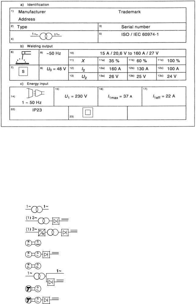
2.1 Information - Shown On Type Plate
The following explanations refer to the numbered boxes shown in Figure 2.3 according to ISO/IEC 60974-1.
a) Identification
Box l |
Name and address of the manufacturer or distributor or importer and, optionally, a trade mark and the |
|
country of origin, if required |
Box 2 |
Type (identification) as given by the manufacturer |
Box 3 |
Traceability of design and manufacturing data, e.g. serial number |
Box 4 |
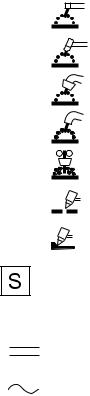
Welding power source symbol (optional) e g |
Single-phase transformer
Singleor three-phase transformer-rectifier
Singleor three-phase static frequency converter-transformer-rectifier
Three-phase motor-generator
Three-phase motor-generator-rectifier
Three-phase rotating frequency Converter
Single-phase combined a.c. and d.c. power source
Engine-a.c. generator
Engine-generator-rectifier
Box 5 Reference to this Standard confirming that the welding power source complies with its requirements
b) Welding Output
Welding process Symbol e.g.:
Manual metal arc welding with covered electrodes
Tungsten inert-gas welding
Metal inert and active gas welding including the use of flux cored wire
Selfshielded flux cored arc welding
Submerged arc welding
Symbol for plasma cutting
Symbol for plasma gouging
Symbol for welding power sources which are suitable for supplying power to welding operations carried out in an environment with increased hazard of electric shock (if applicable).
Welding current symbol e.g.:
Direct current
Alternating current, and additionally the rated frequency in hertz e.g.: ~50 Hz
U0... V Rated no-load voltage
a)Arithmetic mean value in case of direct current
b)RMS value in case of alternating current
c)Ur... V Reduced rated no-load voltage in case of a voltage reducing device
d)Us... V Switched rated no-load voltage in case of an a.c. to d.c. switching device
Box 10 |
... A/... V to... A/... V Range of output, rated minimum and maximum welding current and their |
|
|
corresponding conventional load voltage. |
|
Box 11 |
X Duty cycle (duty factor) symbol. |
|
Box 12 |
I2 |
Rated welding current symbol. |
Box 13 |
U2 |
Conventional load voltage symbol. |
Boxes |
11a, 11b, 11c ...% Values of the duty cycle (duty factor). |
|
|
12a, 12b, 12c ... A Values of the rated welding current. |
|
|
13a, 13b, 13c ... V Values of the conventional load voltage. |
|
These boxes form a table with corresponding values of the three settings:
a)... % duty cycle (duty factor) at the rated maximum welding current;
b)60 % duty cycle (duty factor); and
c)100 % duty cycle (duty factor) as far as relevant.
 Loading...