


170-230
D
Betriebsanleitung
Schutzgas-Schweißgeräte MIG/MAG 170 - 230
GB
F
NL
Operating Instruction
MIG Welding Machines 170 - 230 Amp Models
Notice d´utilisation postes de soudure
semiautomatiques MIG/MAG 170 - 230
Gebruiksaanwijzing
Lasapparaat MIG/MAG 170/230
D
Achtung! Lesen Sie diese Anleitung vor der Installation und Inbetriebnahme aufmerksam durch.
GB
Attention! Carefully read through these instructions prior to installation and commissioning.
F
Attention! Prière de lire attentivement la présente notice avant l'installation et la mise en service.
NL
115 117 3671 / D/GB/F/NL /1303 - 5.1
Attentie! Lees deze instructies voor de installatie en ingebruikname aandachtig door.

Contents
1 Specifications
2 Regulations for the Prevention of Accidents
2.1 Welding Output
3 Operation
4 Installing the Wire Spool
5 Welding Stainless Steel and Aluminium
6 Practical Hints for MIG Welding
7 Maintenance
8 Trouble Shooting
9 Spare Parts List and Accessoires
User Responsibility
This machine will perform in conformity with the description contained in the instructions provided.
This machine must be checked periodically. Defective equipment (including service leads) should not be used.
Parts that are broken, missing, plainly worn, distorted or contaminated, should be replaced immediately. Should
such repair or replacement become neccessary, it is recommended that such repairs are carried out by qualified
persons approved by the equipment manufacturer or its representative. The user of this machine shall have the
sole responsibility for any malfunction which results from improver use or unauthorized modification from standard
specifications, faulty maintenance, damage or improper repair by anyone other than qualifieded persons approved
by the equipment manufacturer or its representatives.
Read and understand this manual before commissioning your machine!
We reserve the right to change specifications.
GB
Product Liability/Warranty
These welding machines shall only be used as specified. Any other use requires the written consent of Metabo GmbH,
Business Unit Elektra Beckum, P.O.Box 1352, D-49703 Meppen, Germany.
This product carries 2 years (5 years on main transformer and choke) manufacturer warranty under the prevailing legal
provisions, which may vary from country to country. Retain proof of purchase! You are only entitled to claim warranty
against proof of purchase. Please see back cover for manufacturer representative's address nearest you.
The warranty period begins with the date of the original purchase by the end user. Proof of purchase should be retained
and must be presented in the event of a warranty claim. This warranty excludes and does not cover defects, malfunction
and failure caused by natural wear, overload, unreasonable use or failure to provide reasonable and necessary
maintenance.
In case of a defect notify your dealer or Elektra Beckum distributor, who will decide how to handle your claim. Warranty
claims can only be taken care of by your Elektra Beckum dealer or authorized service centre.
1 Specifications
MIG/MAG MIG/MAG
170/30 TL 170/30 TL Combi
Welding range 25 - 160 A 25 - 160 A
Open-circuit voltage 15.3 - 22 V 15.3 - 22 V
No-load voltage 19 - 37 V 19 - 38 V
Input capacity 4.0 kVA 3.6/4.0 kVA
Mains 50/60 Hz AC 1 ~ 230 V 1 ~ 230/2 ~ 400 V
Frequency 50-60 Hz 50-60 Hz
Welding steps 6 6
Wire diameter 0.6 - 0.8 mm 0.6 - 0.8 mm
Weldable material 0.5 - 5 mm 0.5 - 5 mm
Duty cycle (25°c/ 40°C ) 160 A 30%/20% 160 A 30%/20%
100% (25°c/ 40°C ) 90 A/60A 90 A/60A
Mains fuse T 16 A T 16 A
Cooling F F
Protection class IP 21 IP 21
Isulation class F F
Welding gun assembly SB 14/2 SB 14/2
Dimensions l x w x h 840x410x580 840x410x580
Weight 61 kg 62 kg

MIG/MAG MIG/MAG MIG/MAG
180/35 ET 200/35 ET 230/40 ET
Combi
Welding range 25 - 180 A 25 - 200 A 25 - 230 A
Open-circuit voltage 15.3 - 23 V 15.3 - 24 V 15.3 - 25,5 V
No-load voltage 17.5 - 33 V 21 - 34 V 19 - 34 V
Input capacity 3.6/4.6 kVA 6 kVA 6.5 kVA
Mains 50/60 Hz AC 1 ~ 230 V/2 ~ 400 V 3 ~ 400 V 3 ~ 400 V
Frequency 50-60 Hz 50-60 Hz 50-60 Hz
Welding steps 6 6 6
Wire diameter 0.6 - 0.8 mm 1,0 mm 0.6 - 1.0 mm
Weldable material 0.5 - 6 mm 0.5 - 7 mm 0.6 - 9 mm
Duty cycle (25°c/ 40°C ) 180 A 35%/25% 200 A 35%725% 230 A 40%/30%
100% (25°c/ 40°C ) 100 A/70A 110 A/75A 140 A/100A
Mains fuse T 16 A T 16 A T 16 A
Cooling F F F
Protection class IP 21 IP 21 IP 21
Isulation class F F F
Welding gun assembly SB 15/2 SB 15/2 SB 25/2
Dimensions l x w x h 840x410x580 840x410x580 840x410x580
Weight 68 kg 75 kg 81HAM kg
StandardScope of delivery: Welding machine with MIG/MAG torch c/w contact tip and gas shroud, pressure
regulator for shielding gas, earth clamp, wire brush and nozzle anti-clogging spray.
delivery:
2 Regulations for the Prevention of Accidents
Know the applicable regulations for electric arc welding and strictly adhere to.
Safety Instructions
● Protection against electrical accidents
- Welding cables are to be firmly connected to ensure proper conducting capacity
- Mains cord and welding cables are to be protected against damages.
- Replace damaged mains cords with genuine Elektra Beckum parts only.
- Place welding gun onto insulating backing during short work break.
- For longer breaks switch off machine.
- When welding, wear dry and insulating gloves and shoes.
- For maintenance and repair work disconnect from power mains.
● Protection against UV rays, burns and fumes
- Wear protective clothing to prevent burns (sleeved gloves, welding apron etc.)
- Always use a welding visor.
- Screen off work place to protect other persons working nearby against UV rays.
- Welding material having a polluted or contaminated surface may generate toxic fumes. Clean surface before
welding.
- Zinc-plated or galvanized material should not be welded as zinc fumes are highly toxic.
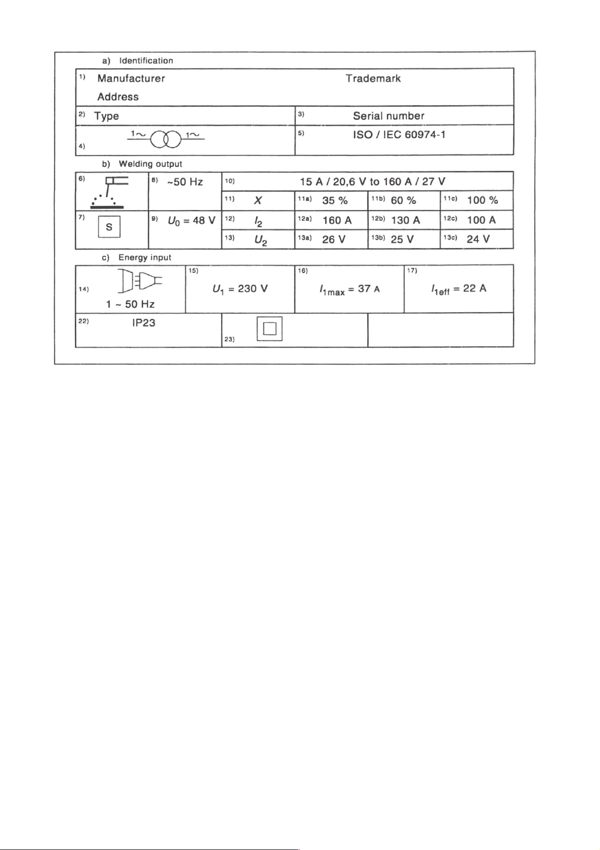
2.1 Welding Output
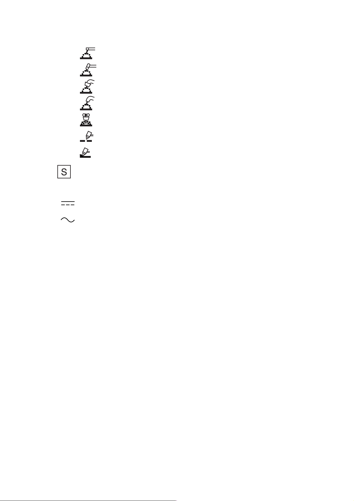
Box 6 Welding process Symbol e.g.:
Manual metal arc welding with covered electrodes
Tungsten inert-gas welding
Metal inert and active gas welding including the use of flux cored wire
Selfshielded flux cored arc welding
Submerged arc welding
Symbol for plasma cutting
Symbol for plasma gouging
Box 7 Symbol for welding power sources which are suitable for supplying power to welding operations
carried out in an environment with increased hazard of electric shock (if applicable).Box 8
Welding current symbol e.g.:
Direct current
Alternating current, and additionally the rated frequency in
hertz e.g.: ~50 Hz
Box 9 U0... V Rated no-load voltage
a) Arithmetic mean value in case of direct current
b) RMS value in case of alternating current
c) Ur... V Reduced rated no-load voltage in case of a voltage reducing device
d) Us... V Switched rated no-load voltage in case of an a.c. to d.c. switching device
Box 10 ... A/... V to... A/... V Range of output, rated minimum and maximum welding current and their
corresponding conventional load voltage.
Box 11 X Duty cycle (duty factor) symbol.
Box 12 I2 Rated welding current symbol.
Box 13 U2 Conventional load voltage symbol.
Boxes 11a, 11b, 11c ...% Values of the duty cycle (duty factor).
12a, 12b, 12c ... A Values of the rated welding current.
13a, 13b, 13c ... V Values of the conventional load voltage.
These boxes form a table with corresponding values of the three settings:
a) ... % duty cycle (duty factor) at the rated maximum welding current;
b) 60 % duty cycle (duty factor);
and
b) Welding Output
Box 6 Welding process Symbol e.g.:
Manual metal arc welding with covered electrodes
Tungsten inert-gas welding
Metal inert and active gas welding including the use of flux cored wire
Selfshielded flux cored arc welding
Submerged arc welding
Symbol for plasma cutting
Symbol for plasma gouging
Box 7 Symbol for welding power sources which are suitable for supplying power to welding operations
carried out in an environment with increased hazard of electric shock (if applicable).
Box 8 Welding current symbol e.g.:
Direct current
Alternating current, and additionally the rated frequency in
hertz e.g.: ~50 Hz
Box 9 U0... V Rated no-load voltage
a) Arithmetic mean value in case of direct current
b) RMS value in case of alternating current
c) Ur... V Reduced rated no-load voltage in case of a voltage reducing device
d) Us... V Switched rated no-load voltage in case of an a.c. to d.c. switching device
Box 10 ... A/... V to... A/... V Range of output, rated minimum and maximum welding current and their
corresponding conventional load voltage.
Box 11 X Duty cycle (duty factor) symbol.
Box 12 I2 Rated welding current symbol.
Box 13 U2 Conventional load voltage symbol.
Boxes 11a, 11b, 11c ...% Values of the duty cycle (duty factor).
12a, 12b, 12c ... A Values of the rated welding current.
13a, 13b, 13c ... V Values of the conventional load voltage.
These boxes form a table with corresponding values of the three settings:
a) ... % duty cycle (duty factor) at the rated maximum welding current;
b) 60 % duty cycle (duty factor);
and
c) 100 % duty cycle (duty factor) as far as relevant.
Column a) need not be used if the duty cycle (duty factor) for the rated maximum welding
current is 60 % or 100 %.
Column b) need not be used if the duty cycle (duty factor) at the rated maximum welding current is 100 %.
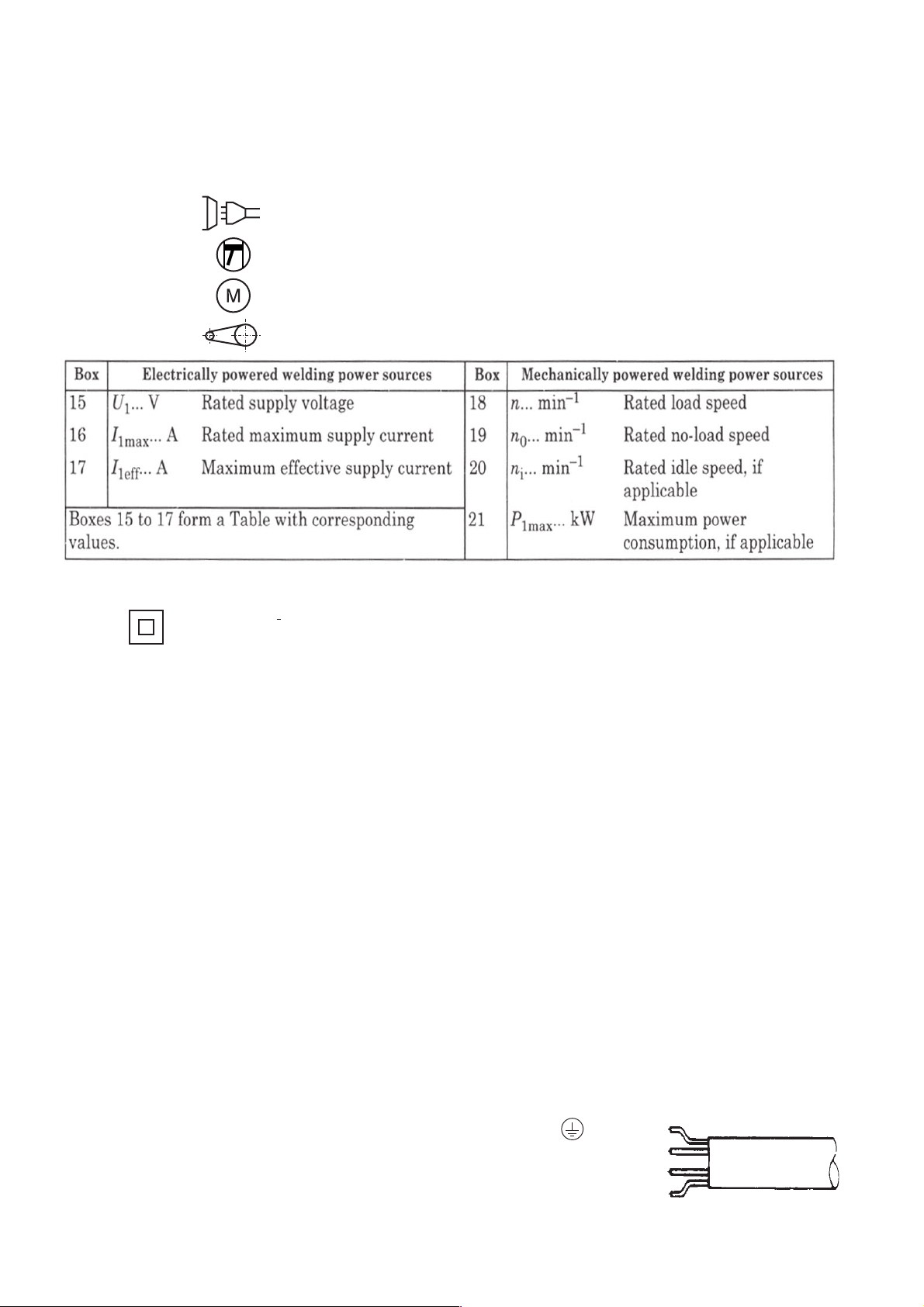
c) Energy input
Box 14 Energy input symbol e.g.:
Input supply, number of phases (e.g. l or 3), symbol for
alternating current
and the rated frequency (e.g. 50 Hz or 60 Hz)
Engine
Motor
Belt drive
Box 22 IP.. Degree of protection, e.g. IP21 or IP23.
Box 23 Symbol for protection class II, if applicable.
3 Operation
Initiation
Connect cable assembly to central coupling (1). Be sure that collar nut is fully tightened. Plug earth cable into socket
(7) and lock in position.
Place gas sylinder onto rack at rear of machine and secure with chain. Attach gas hose to pressure regulator and
secure with hose clamp provided.
Open gas cylinder valve briefly to clear any foreign matter from it, than attach pressure regulator.
Set regulator to required gas flow rate (approx. 10 - 13 ltr./min. - 2.5 - 3 GPM).
Caution: Do not dismantle the pressure regulator for any reason. It may explode when assembled incorrectly!
1-Phase Machines
These machines come fitted with a Schuko 2-prong
plug with earth contact as standard. For the U. K. and
certain other markets machines are supplied without
a plug on the power cord. Connect to power mains
only by earthed plug and earthed receptacle matchine
your local standard. Mains furse 16 amp time-lag
required.
3-Phase Machines
Three-phase machines are supplied with a CEE 5-pin
plug on the power cord. If a plug matching your local
standard has to be installed, connect only as shown at
right. The yellow/green earth lead must be connected
to the terminal marked .
Wiring diagram for Elektra Beckum
3 phase MIG welding machines
earth lead yellow/green
L1
L2
L3
 Loading...