


 Loading...
20 |
30 |
40 |
50 |
GPS System 500 |
|
|
|
|
|
|
|
|
|
|
Technical Reference Manual
Version 4.0
English

System GPS500
Congratulations on your purchase of Leica System 500
To use equipment in the permitted manner, please refer to the detailed safety instructions in the User Manual.
|
2 |
Technical Reference Manual-4.0.0en |

Technical Support
Technical Support is provided by Leica Geosystem’s worldwide network of representatives. We are represented in almost every country in the world. A representative directory is available at:
www.leica-geosystems.com
Technical Reference Manual-4.0.0en |
3 |
|

Symbols used in this manual
Important paragraphs which must be adhered to in practice as they enable the product to be used in a technically correct and efficient manner.
Symbols used in this manual |
4 |
Technical Reference Manual-4.0.0en |

View of chapters
Chapter 1 |
- Introduction |
|
|
11 |
||
|
|
|
|
|
||
Chapter 2 |
- Equipment Setup and Connection |
|
20 |
|||
|
|
|
|
|||
Chapter 3 |
- Using System 500 without a Terminal |
70 |
||||
|
|
|
|
|
||
Chapter 4 |
- TR500 Terminal Overview |
|
74 |
|||
|
|
|
|
|
||
Chapter 5 |
- Configuring the Receiver |
|
86 |
|||
|
|
|
|
|
||
Chapter 6 |
- Jobs and Points |
|
156 |
|||
|
|
|
|
|
||
Chapter 7 |
- Measuring with System 500 |
|
158 |
|||
|
|
|
|
|
||
Chapter 8 |
- Coding |
|
232 |
|||
|
|
|
|
|
||
Chapter 9 |
- The CONFIG key |
|
241 |
|||
|
|
|
|
|
||
Chapter 10 |
- Status |
|
259 |
|||
|
|
|
|
|
||
Chapter 11 |
- Applications |
|
273 |
|||
Chapter 12 |
|
|
|
|
||
- Utilities |
|
307 |
||||
Chapter 13 |
|
|
|
|
||
- Transfer |
|
310 |
||||
Appendices |
|
|
|
|
|
|
|
|
|
321 |
|||
|
|
|
|
|
|
|
Technical Reference Manual-4.0.0en |
|
5 |
|
View of chapters |
|
|

Contents
1. Introduction .............................................. |
11 |
2.10 Equipment Setup - Real-Time Rover, |
|
|||
1.1 The GPS Antenna ............................................... |
12 |
All on Pole, direct clip of TR500 on to Sensor ....... |
48 |
|||
1.2 The GPS Receiver ............................................... |
13 |
2.11 Equipment Setup - Real-Time Rover, |
|
|||
1.3 The TR500 Terminal ............................................ |
15 |
All on Pole, TR500 and Sensor separated ............ |
51 |
|||
1.4 Data Storage ....................................................... |
16 |
2.12 Equipment Setup - Real Time Rover, GIS Rover . 54 |
||||
1.5 Batteries/Power Supply ........................................ |
18 |
2.13 Equipment Setup - Repeater Station and |
|
|||
1.5.1 Charging the Batteries ......................................... |
19 |
Repeater Box ...................................................... |
58 |
|||
2. Equipment Set Up and Connection |
20 |
2.14 Using the Minipack ............................................ |
61 |
|||
2.15 Measuring Antenna Heights |
63 |
|||||
2.1 GPS Receiver ports |
21 |
|||||
2.15.1 Mechanical Reference Planes ........................... |
64 |
|||||
2.2 Equipment Setup - Post Processed Static/Rapid |
|
2.15.2 Antenna Height components ............................. |
65 |
|||
Static/Reference on Pillar .................................... |
22 |
2.15.3 Measuring Slope Heights ................................... |
69 |
|||
2.3 Equipment Setup - Post Processed Static/Rapid |
|
3. Using System 500 without a Terminal |
70 |
|||
Static/Reference on Tripod |
25 |
|||||
3.1 Setting up the Equipment |
71 |
|||||
2.4 Equipment Setup - Post Processed Kinematic, |
|
|||||
|
3.2 Operation |
71 |
||||
Minipack and Pole |
28 |
|||||
3.3 Shut Down |
71 |
|||||
2.5 Equipment Setup - Post Processed Kinematic, |
|
|||||
|
3.4 LED Indicators |
72 |
||||
All on Pole, Direct Clip of TR500 on to Sensor |
32 |
|||||
3.4.1 Power LED |
72 |
|||||
2.6 Equipment Setup - Post Processed Kinematic, |
|
|||||
|
3.4.2 Satellite Status LED |
72 |
||||
All on Pole, TR500 and Sensor separated |
35 |
|||||
3.4.3 Memory Status LED |
73 |
|||||
2.7 Equipment Setup - Real Time Reference, |
|
|||||
|
3.5 Field Record Sheet |
73 |
||||
single tripod |
38 |
|||||
4. TR500 Terminal Overview |
74 |
|||||
2.8 Equipment Setup - Real-Time Reference, |
|
|||||
Two Tripods ...................................................... |
41 |
4.1 Screen Layout ..................................................... |
75 |
|||
2.9 Equipment Setup - Real-Time Rover, |
|
4.2 Status Icons ........................................................ |
77 |
|||
Pole and Minipack ............................................... |
44 |
4.3 Keyboard ............................................................. |
82 |
|||
|
|
|
4.4 General Operating Principles ............................... |
83 |
||
|
|
|
|
|
||
Contents |
|
6 |
|
Technical Reference Manual-4.0.0en |
||

Contents, continued
5. Configuring the Receiver ........................ |
86 |
5.1 Configuring the Receiver for Static and Rapid Static |
|
Operations .......................................................... |
88 |
5.1.1 Advanced Operation Mode for Static and Rapid |
|
Static .................................................................... |
95 |
5.2 Configuring the Receiver for Post-Processed |
|
Kinematic Operations .......................................... |
99 |
5.2.1 Advanced Operation Mode for Post-Processed |
|
Kinematic ........................................................... |
112 |
5.3 Configuring the Receiver for Real-Time Reference |
|
Operations ......................................................... |
116 |
5.3.1 Advanced Operation Mode for Real Time |
|
Reference Stations ............................................. |
124 |
5.4 Configuring the Receiver for Real-Time Rover |
|
Operations ........................................................ |
127 |
5.4.1 Advanced Operation Mode for Real Time Rover 148 |
|
6. Jobs and Points..................................... |
156 |
6.1 Management of Jobs ......................................... |
156 |
7. Measuring with System 500 ................. |
158 |
7.1 Static and Rapid Static Survey, Post-Processed |
|
Kinematic Reference ......................................... |
159 |
7.1.1 Overview of Procedure ...................................... |
160 |
7.1.2 Adding the Point Id ............................................ |
160 |
7.1.3 Adding the Antenna Height ................................ |
161 |
7.1.4 Adding a Code ................................................... |
161 |
7.1.5 Adding a Starting Time ...................................... |
163 |
7.1.6 Measuring procedure ......................................... |
163 |
7.1.7 Using the ADD key ............................................ |
166 |
7.2 Post-processed Kinematic Survey (Rover) ......... |
167 |
7.2.1 Overview of Procedure ...................................... |
168 |
7.2.2 Adding the Point Id ............................................ |
168 |
7.2.3 Adding the Antenna Height ................................ |
169 |
7.2.4 Adding a Code ................................................... |
170 |
7.2.5 Adding a Starting Time ...................................... |
171 |
7.2.6 Measuring Procedure ........................................ |
172 |
7.2.7 Using the AUTO key .......................................... |
174 |
7.2.8 Using the ADD key ............................................ |
174 |
7.3 Real-Time Reference Stations ........................... |
176 |
7.3.1 Measuring procedure ......................................... |
177 |
7.3.2 Using the ADD key ............................................ |
180 |
7.4 Real-Time Rover, Surveying New Points ............ |
181 |
7.4.1 Overview of Procedure ...................................... |
182 |
7.4.2 Adding the Point Id ............................................ |
182 |
7.4.3 Adding the Antenna Height ................................ |
183 |
7.4.4 Adding a Code ................................................... |
184 |
7.4.5 Adding a Starting Time ...................................... |
185 |
7.4.6 Measurement Procedure ................................... |
186 |
7.4.7 Using the AUTO key .......................................... |
190 |
7.4.8 Using the INIT key ............................................. |
193 |
7.4.9 Using the ADD key ............................................ |
194 |
7.4.10 Using the NEAR key ........................................ |
206 |
7.4.11 Radio Down Infill .............................................. |
206 |
Technical Reference Manual-4.0.0en |
7 |
Contents |

Contents, continued
7.5 Real-Time Rover, Staking Out ............................ |
208 |
7.5.1 Entering Stakeout .............................................. |
208 |
7.5.2 Stake-Out Types ................................................ |
209 |
7.5.3 The Stake-Out Screen ....................................... |
210 |
7.5.4 Orientation ......................................................... |
211 |
7.5.5 Polar and Orthogonal ........................................ |
215 |
7.5.6 Using the Reverse function ................................ |
216 |
7.5.7 Using the Redraw function ................................. |
217 |
7.5.8 Picking up a new point ....................................... |
217 |
7.5.9 Using the INIT key ............................................. |
217 |
7.5.10 Using the NEAR key ........................................ |
218 |
7.5.11 Graph .............................................................. |
218 |
7.5.12 Aux Pt .............................................................. |
219 |
7.5.13 Point Stake-Out - Procedure ............................ |
220 |
7.5.14 Slope Stake-Out - Procedure ........................... |
222 |
7.5.15 Grid Stake-Out - Procedure ............................. |
226 |
8. Coding .................................................... |
232 |
8.1 Thematical Coding ............................................. |
232 |
8.1.1 Importing, Selecting and Defining a |
|
Thematical Codelist ............................................ |
233 |
8.1.2 Defining New Codes and Attributes ................... |
234 |
8.1.3 Defining and Activating/Deactivating Layers ...... |
235 |
8.1.4 Adding a Thematical Code to a Point ................. |
236 |
8.2 Free Coding ...................................................... |
237 |
8.2.1 Importing, Selecting and Defining a |
|
Free Codelist ...................................................... |
237 |
8.2.2 Defining New Codes .......................................... |
238 |
8.2.3 Adding a Free Code .......................................... |
239 |
9. The CONFIG Key ................................... |
241 |
9.1 Survey - Satellite ................................................ |
242 |
9.2 General - Units .................................................. |
243 |
9.3 General - Language ........................................... |
244 |
9.4 General - Hot Keys ............................................ |
244 |
9.5 General - Time and Initial Position ...................... |
245 |
9.6 General - Start-Up ............................................. |
245 |
9.7 General - TR500 ................................................ |
246 |
9.8 General - Identification ....................................... |
247 |
9.9 Interfaces ......................................................... |
247 |
9.10 Interfaces - Real-Time ..................................... |
247 |
9.11 Interfaces - NMEA Output ................................ |
248 |
9.12 Interfaces - ASCII Input .................................... |
249 |
9.13 Interfaces - Hidden Point .................................. |
253 |
9.14 Interfaces - GSI/User Out ................................. |
253 |
9.15 Interfaces - Remote ......................................... |
254 |
9.16 Interfaces - PPS Out ........................................ |
255 |
9.17 Interfaces - Event Input .................................... |
256 |
10. Status ................................................... |
259 |
10.1 Real-Time Input Status .................................... |
259 |
10.2 Stop and Go Indicator ...................................... |
261 |
10.3 Position ........................................................... |
263 |
10.4 Logging Status ................................................. |
266 |
10.5 Satellite Status ................................................. |
267 |
10.6 Point Log Status .............................................. |
269 |
Contents |
8 |
Technical Reference Manual-4.0.0en |

Contents, continued
10.7 Code Log Status .............................................. |
270 |
10.8 Message Log Status ........................................ |
270 |
10.9 Memory/Battery Status ..................................... |
270 |
10.10 Sensor Status ................................................ |
271 |
10.11 Software Version Status ................................. |
271 |
10.12 Interfaces Status ............................................ |
272 |
11. Applications ......................................... |
273 |
11.1 Determining a Coordinate System .................... |
273 |
11.2 Adding Points to Existing Coordinate Systems .. |
283 |
11.3 Point Management ........................................... |
284 |
11.4 Calculator ........................................................ |
288 |
11.5 Wake-up Sessions ........................................... |
288 |
11.6 COGO ............................................................. |
290 |
11.7 Area ................................................................ |
303 |
11.8 Line Division .................................................... |
304 |
12. Utilities ................................................. |
307 |
12.1 Directory of Memory Device ............................. |
307 |
12.2 Format Memory Module ................................... |
308 |
12.3 Enter Security Code ......................................... |
309 |
12.4 Self Test .......................................................... |
309 |
13. Transfer ................................................ |
310 |
13.1 Job .................................................................. |
310 |
13.2 Config Set ....................................................... |
310 |
13.3 Coordinate System ........................................... |
311 |
13.4 Antenna Info ..................................................... |
311 |
13.5 Codelist ............................................................ |
311 |
13.6 ASCII/GSI to Job ............................................ |
312 |
13.7 GSI / User ....................................................... |
314 |
13.8 Geoid Field File ................................................ |
316 |
13.9 CSCS Field File ............................................... |
316 |
13.10 Firmware ....................................................... |
316 |
13.11 Firmware TR500 ............................................ |
317 |
13.12 Language Version .......................................... |
317 |
13.13 Application Text .............................................. |
317 |
13.14 Almanac ........................................................ |
318 |
13.15 Account File ................................................... |
318 |
13.16 CFC Log Mask File ........................................ |
318 |
13.17 Beacon Station List ....................................... |
319 |
13.18 Modem/GSM Station List ............................... |
319 |
13.19 System ......................................................... |
319 |
13.20 Any File Type ................................................. |
320 |
Appendix A - Operating and Storage |
|
Temperatures ............................................. |
321 |
Appendix B - Observation Times ............. |
322 |
Appendix C - Seismic Record Format ..... |
323 |
Appendix D - Defined Line File Format ... |
324 |
Technical Reference Manual-4.0.0en |
9 |
Contents |

Contents, continued
Appendix E - NMEA Message Formats .... |
325 |
GGA - Global Positioning System Fix Data ............... |
327 |
GGK - Real-Time Position with DOP ........................ |
328 |
GGK(PT) - Real-Time Position with DOP ................. |
328 |
GGQ - Real-Time Position with CQ .......................... |
329 |
GLL - Geodetic Position - Latitude, Longitude ........... |
329 |
GNS - GNSS Fix Data ............................................. |
330 |
GSA - GPS DOP and Active Satellites ..................... |
330 |
GSV - GPS Satellites in View ................................... |
331 |
LLK - Leica Local Position and GDOP ...................... |
331 |
LLQ - Leica Local Position and Quality ..................... |
332 |
VTG - Course Over Ground and Ground Speed ....... |
332 |
ZDA - Time and Date ............................................... |
333 |
Appendix F - Pin Assignments and |
|
Sockets ...................................................... |
334 |
Appendix G - Data Device Directory |
|
Structure .................................................... |
336 |
Appendix H - External Devices................. |
338 |
RS232 .................................................................... |
339 |
Radio and Repeaters ............................................... |
340 |
GSM ....................................................................... |
344 |
Modem ................................................................... |
350 |
RTB Module (CSI) ................................................... |
352 |
RTS Module (Racal) ................................................ |
354 |
SAPOS ................................................................... |
356 |
Using a SAPOS decoder box ..................................... |
356 |
Using a SMARTgate box ............................................ |
357 |
Using the Telemax Service ......................................... |
359 |
Hidden Point ........................................................... |
361 |
Appendix I - MC500 ................................... |
364 |
Appendix J - RS500 ................................... |
369 |
Appendix K- GS50 / GS50+ and GIS Data |
|
Collection ................................................... |
377 |
Hardware and Accessories ...................................... |
378 |
Compact Flash and Sensor Transfer........................ |
382 |
Operation and Configuration .................................... |
383 |
The CONFIG Key .................................................... |
384 |
The STATUS Key .................................................... |
388 |
Data Collection with the GS50 and GS50+ ............... |
389 |
|
10 |
Technical Reference Manual-4.0.0en |
1. Introduction
System 500 is used to receive signals from GPS satellites which are then processed to obtain a position on the earth’s surface.
It can be used in many applications, the main ones being Land Survey, Stakeout and Hydrographic Survey.
The main components of System 500 are the GPS Antenna and GPS Receiver. Ancilliary components are the Terminal, Batteries, PC Cards and cables.
SKI-Pro, a PC based software is also used in conjunction with the hardware listed above for post-processing GPS data and for downloading coordinates
recorded in the field. Instructions for System 500 - main hardware components using SKI-Pro can be found in the
accompanying printed guides and online help.
Technical Reference Manual-4.0.0en |
11 |
1. Introduction |

1.1 The GPS Antenna
There are several System 500 GPS Antennas available. These are:
•AT501 Single Frequency Antenna.
•AT502 Dual Frequency Antenna.
•AT503 Dual Frequency Choke Ring Antenna.
•AT504 JPL Design Dual Frequency Choke Ring Antenna.
•Single Frequency Choke Ring Antenna.
The GPS Antenna is selected for use based upon the application. The vast majority of applications will require the AT501 or AT502 Antenna.
The AT501 is a L1 single frequency antenna. Use it with the SR510 Receiver. The AT502 is a dual frequency antenna. Use it with the SR520 or SR530 Receiver.
The Choke Ring Antennas are designed for use where the utmost precision is required. Typical applications include Static Surveys of long baselines, Tectonic Plate monitoring, Reference Stations, etc.
Use the AT503 and AT504 with the SR520 or SR530 Receiver. Use the Single Frequency Choke Ring with the SR510 Receiver.
Also available is a combined GPS/
AT502 Antenna
RTB or GPS/ RTS antenna. Refer to Appendix K for further information.
AT504 Antenna
1. Introduction |
12 |
Technical Reference Manual-4.0.0en |

1.2 The GPS Receiver
The GPS Receiver is the instrument that processes the GPS signals received by the GPS Antenna.
There are six different models of GPS receiver in System 500. The model number is printed on the PC card lid.
See the detailed descriptions of each of these receivers given down below.
SR510 - Tracks the L1 C/A code and uses it to reconstruct the carrier phase. Data can be stored for postprocessing in SKI-Pro. Baselines can be calculated with a precision of up to about 5-10mm +2ppm.
With a radio modem attached the receiver can be used for real-time measurements accepting RTCM code corrections. Coordinates can be calculated with a precision of up to about 0.5m.
SR520 - Tracks the L1 C/A code and L2 P-code to reconstruct the carrier phase. When Anti-Spoofing (A-S) is activated, the receiver switches to a patented P-code aided tracking technique that provides full L2 carrier measurements and L2 pseudoranges. Data can be stored for post-processing. Baselines can be calculated with a precision of up to about 3-10mm +1ppm.
With a radio modem attached the receiver can be used for real-time measurements accepting RTCM code corrections. Coordinates can be calculated with a precision of up to about 0.5m.
SR530 - Tracks the L1 C/A code and L2 P-code to reconstruct the carrier phase. When Anti-Spoofing (A-S) is activated, the receiver switches to a patented P-code aided tracking technique that provides full L2 carrier
measurements and L2 pseudoranges. A radio modem attaches and the receiver can be used for RTK operations. Coordinates can be calculated with a precision of up to about 1cm
Data can also be stored for postprocessing. Baselines can be calculated with a precision of up to about 3-10mm +1ppm.
System 500 GPS Receivers can be operated with or without the TR500 Terminal (see section 1.3). The TR500 is used for field data acquisition and for configuring the receiver.
Details of using the Receiver without a Terminal are given in Chapter 3.
Technical Reference Manual-4.0.0en |
13 |
1. Introduction |

MC500 - A ruggedized version of the SR530 designed specifically for Machine Control. Can also be utilised as a dedicated GPS Reference Station. Please refer to Appendix I for specific details.
RS500 - A dedicated GPS Reference Sation receiver designed for permanent installation. Please refer to Appendix J for specific details.
GS50 - This receiver has been specifically designed for GIS applications. Please refer to Appendix K for more information that is specific to the GS50 and the corresponding PCsoftware GIS DataPRO.
1. Introduction |
14 |
Technical Reference Manual-4.0.0en |
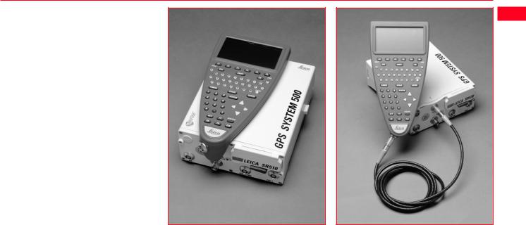
1.3 The TR500 Terminal
The TR500 Terminal provides a full user interface to all System 500 GPS Receivers.
It can be used to set parameters in the receiver and to steer the GPS measurement operation.
The TR500 can be used to set and store parameters in one GPS receiver and then removed and used to set parameters in another System 500 receiver. The receiver can then be used in the field without the TR500 attached. Note that whilst this is possible when measuring in any mode, for a Reference or Rover, it is recommended that the Receiver only be used without a TR500 at Reference stations or with Static/Rapid Static Rovers.
The TR500 is connected either |
TR500 mounted on the Receiver |
TR500 connected using the cable |
||
|
|
|
|
|
directly to the receiver or via a cable. |
|
|
|
|
Data input is via a fully alphanumeric |
|
|
|
|
QWERTY keyboard and an LCD |
|
|
|
|
display of 32 x 12 characters which |
|
|
|
|
may be illuminated. |
|
|
|
|
|
|
|
|
|
Technical Reference Manual-4.0.0en |
|
15 |
|
1. Introduction |

1.4 Data Storage
Data is stored on either an Internal Memory or PC Card. The PC Card is the preferred data storage medium. The Internal Memory is an option.
The PC Card is inserted into the slot on the front of the GPS Receiver. PC Cards are available from Leica with varying capacities. Note that whilst other PC Cards may be used, Leica recommend Leica PC cards only and cannot be held responsible for data loss or any other error that may occur whilst using a non-Leica card.
To insert the PC Card in the GPS Receiver, open the card slot door, with the Leica Logo uppermost and facing you, slide the card into the slot firmly until it clicks into position. Press the eject button at the side of the card to remove it.
The Internal Memory is available in |
|
8MB or 16MB capacities and resides |
|
in the Receiver. When data has to be |
|
downloaded to SKI-Pro, connection is |
|
made between port 2 on the Receiver |
|
and a serial port on the PC. |
|
The memory device is checked |
|
before starting a survey. If it is more |
|
than 80% full, an information mes- |
|
sage appears. |
|
Inserting the PC Card |
|
Follow the care instructions shown on |
|
the rear of the card. Keep the card |
|
dry, only use within the specified |
|
temperature range, do not bend the |
|
card and protect it from direct shock. |
|
Failure to follow these instructions |
|
could result in data loss and/or |
|
permanent damage to the card. |
|
The card can become very hot during |
|
use. Avoid touching the metal parts of |
|
the card after prolonged use. |
|
1. Introduction |
16 |
Technical Reference Manual-4.0.0en |

PC Card versus Internal Memory
The PC Card is the preferred data storage medium as it has the following advantages over internal memory:
•Faster download times. A PC Card download using a PC Card Reader or PCMCIA port is virtually instantaneous. Internal memory has to download through a serial connection and can take time.
•Flexibility / no downtime of GPS Receiver. A PC Card can be removed from a receiver when it is full and replaced with a spare. The Receiver does not
have to be taken back to the office for downloading.
Using an Internal Memory means however that the data has less chance of being misplaced or lost. This can happen when multiple PC Cards are used for the same project.
If you are not sure about which type of memory to use, try using a PC card but don’t remove it from the Receiver. You can still download as if it were Internal Memory through any port.
Technical Reference Manual-4.0.0en |
17 |
1. Introduction |
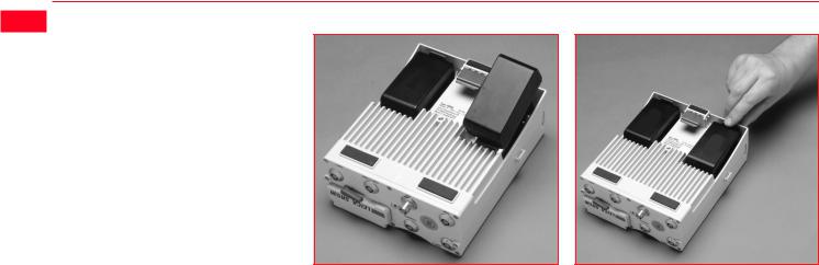
1.5 Batteries/Power Supply
Connecting a GEB121 Battery |
Removing a GEB121 Battery |
System 500 will normally be powered by two GEB121 camcorder type batteries. which plug into the underside of the GPS receiver.
Two batteries, fully charged, will power the SR510 and TR500 for about 7.5 hours continuously and the SR520/530 for about 6 hours continuously.
Operating times will be shorter when working in cold weather and when a radio modem is connected.
Plug in and remove the GEB121 batteries as shown opposite.
System 500 can also be powered by the GEB71 7Ah battery or any 12V DC power supply via either power port, on the front face of the receiver using an appropriate cable.
With the Receiver upside down and the Leica logo on the battery facing you, locate one end into the battery bay. Press the opposite end of the battery down until it audibly clicks into place.
Pull and hold the battery catch. Withdraw the battery with the other hand.
The battery contains toxic material and must be disposed of in an environmentally friendly manner. Do not dispose of the battery in normal household or office waste.
1. Introduction |
18 |
Technical Reference Manual-4.0.0en |

1.5.1 Charging the Batteries
GEB121 Batteries |
Chargers |
|
The batteries are delivered |
|
|
||||
GEB121 Batteries can be charged |
The GKL122 is an intelligent charger. |
|
from the factory totally |
|
|
||||
discharged. They will require a full |
||||
using the GKL122 or GKL111 battery |
It will charge the batteries by the |
|||
charging cycle before the equipment |
||||
chargers. The preferred model is the |
exact amount required. This maxi- |
|||
can be used. For full instructions on |
||||
GKL122. |
mizes battery life. The GKL122 can |
|||
battery charging, refer to the manual |
||||
|
charge up to 2 GEB121 batteries at |
|||
|
accompanying the charger you are |
|||
|
once. The GDI121 extension plate |
|||
GEB71 Batteries |
using. |
|||
enables a further two batteries to be |
||||
|
|
|
||
GEB71 Batteries can be charged |
charged from the same charger at the |
|
|
|
using the GKL122 battery charger |
same time. |
|
|
|
only. |
Additionally, the GKL122 can charge |
|
|
|
|
|
|
||
|
up to two GEB71 batteries. |
|
|
|
|
The GKL111 battery charger is a |
|
|
|
|
simple charger. It will charge one |
|
|
|
|
GEB121 battery at a time. It will |
|
|
|
|
charge the batteries by the exact |
|
|
|
|
amount required. This maximizes |
|
|
|
|
battery life. |
|
|
|
Technical Reference Manual-4.0.0en |
19 |
1. Introduction |
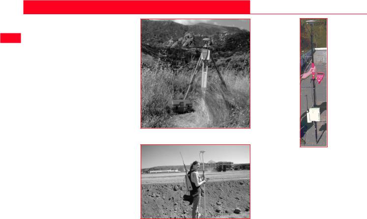
2. Equipment Set Up and Connection
The type of equipment set up that is used will vary with the type of site occupation and the measuring mode. This also applies to the way in which the various components are connected together. There are optimal solutions for setting up the equipment on a tripod, in a backpack and on the pole.
Set up on Tripod
Set up on Unipole
Set up on pole with Minipack
2. Set-up and Connection |
20 |
Technical Reference Manual-4.0.0en |
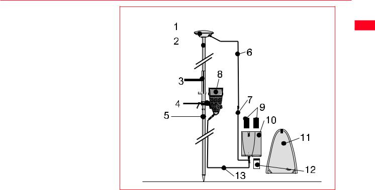
2.1 GPS Receiver ports
All other components of System 500 connect to the GPS Receiver.
The TR500 Terminal fits either directly on the Receiver or can be connected to the Terminal port using a cable.
A Radio Modem in a housing can also be fitted directly to the Receiver. Alternatively, if the housing is not being used, the radio modem can be connected to Port 1 or Port 3 using a cable.
The Antenna is connected to the Receiver via the ANT Port.
External power can be connected via a cable through Port 2.
12 |
11 |
|
|
PORT 3 |
|
|
1 |
|
|
2 |
ON |
TERMINAL |
|
||
EVENT1 |
OFF |
|
|
|
|
3 |
|
|
|
PPS |
|
PWR |
|
ANT |
4 |
5 |
6 |
1.Port 3. 8 pin Lemo.Power/data in/out
2.Event Input 1 (Optional)
3.5 pin Lemo. Power
4.Power ON/OFF
5.PPS Output (Optional)
6.GPS Antenna in
7.Event Input 2 (Optional)
 LEICA SR530
EVENT2
|
PORT 2/PWR |
|
PORT 1 |
7 |
8 |
9 |
10 |
8.Port 2. 5 pin Lemo. Power/data in/out.
9.Pressure equalisation vent.
10.Port 1. 8 pin Lemo. Power/data in/out.
11.PC Card door.
12.Terminal in/out or Remote Interface in/out.
SR530 Receiver, front panel
Technical Reference Manual-4.0.0en |
21 |
2. Set-up and Connection |

2.2 Equipment Setup - Post Processed Static/Rapid Static/Reference on Pillar
 Use
Use
Static/Rapid Static operations or as Reference for Kinematic.
The Receiver and TR500 (if used) can be assembled to make one unit. One connection is made to the GPS Antenna which is mounted on the Pillar. The Receiver and TR500 can be kept in the case. Note that the Receiver can be programmed with the TR500 prior to use which can then be omitted from the set up.
Assumptions
1.GPS Antenna is mounted directly using screw fitting. If using stub and GAD 31 adapter, procedures may vary slightly.
2.GPS Antennas are AT501 or AT502. Procedures/ setup may vary if AT503, 504 or single frequency choke ring are used.
2. Set-up and Connection |
22 |
Technical Reference Manual-4.0.0en |

Equipment Checklist
1.GPS Antenna AT501, 502, 503, 504 or 505
2.GRT146 Carrier
3. GDF122 or GDF112 Tribrach
4. Pillar Plate (if required)
5. GEV120 2.8m Antenna Cable
6. 2, GEB121 Batteries
7. SR510/520/530 GPS Receiver
8. TR500 Terminal (if required)
9. MCF XMB-3 PC Flash Card.
10.GVP602 System 500 Transport Case.
Technical Reference Manual-4.0.0en |
23 |
2. Set-up and Connection |

 Procedure
1.If a pillar plate is being used, locate it on the pillar.
2.Screw the tribrach to the pillar plate or the pillar. Level the tribrach.
3.Place and lock the GRT146 Carrier in the Tribrach.
4.Screw the Antenna onto the Carrier.
5.Check that the Tribrach is still level.
6.Connect the GPS Receiver to the Antenna using the GEV120 Antenna cable.
7.Plug the GEB121 batteries into the GPS Receiver.
8.Attach the TR500 Terminal to the Receiver if required.
9.Insert the PCMCIA Flash Card into the Receiver.
10.Switch on the system using the ON/OFF button.
11.The Receiver can be placed in the Transport Case for additional protection.
The Next Steps
If the Receiver has been pre-pro- grammed and the TR500 is not being used, further guidance is available in Chapter 3.
If the Receiver has been pre-pro- grammed and the TR500 is being used, further guidance is available in Chapter 7.
If the Receiver requires programming with the TR500, further guidance is available in Chapter 5.
When Using the GAD31 adapter and GRT144 carrier,
ensure that the Antenna and GAD31 assembly slide down the full length of the GRT144 stub. An incorrectly mounted Antenna will have a direct effect on your results.
In wet conditions the Receiver can be placed in the
transport case during use for extra protection. Try to shut the case as completely as possible.
If the Receiver is left in the case during use in tempera-
tures exceeding 25°C, the lid should be left open. Refer to Appendix A for operating and storage temperatures.
Use an external battery such as GEB71 to extend the
operating time past 6 hours.
2. Set-up and Connection |
24 |
Technical Reference Manual-4.0.0en |

2.3 Equipment Setup - Post Processed Static/Rapid Static/Reference on Tripod
Use
Static/Rapid Static operations or as Reference for Kinematic.
The Receiver and TR500 (if used) can be assembled to make one unit. This clips to the tripod leg or is placed in the transport container. One connection is made to the Antenna. Note that the Receiver can be programmed with the TR500 prior to use which can then be omitted from the set up.
Assumptions
1.GPS Antenna is mounted directly using screw fitting. If using stub and GAD 31 adapter, procedures may vary slightly.
2.GPS Antennas are AT501 or AT502. Procedures/ setup may vary if AT503, 504 or single frequency choke ring are used.
Technical Reference Manual-4.0.0en |
25 |
2. Set-up and Connection |
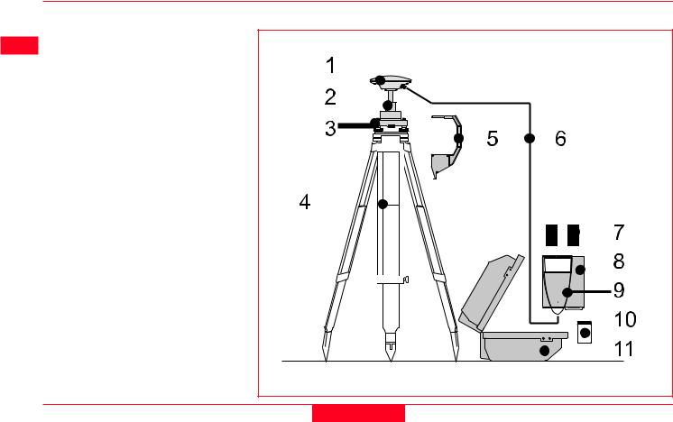
Equipment Checklist |
|
|
|
1. |
GPS Antenna AT501 or AT502 |
|
|
2. |
GRT146 Carrier |
|
|
3. |
GDF122 or GDF112 Tribrach |
|
|
4. |
GST20, GST05 or GST05L |
|
|
|
Tripod |
|
|
5. |
GZS4 Height Hook |
|
|
6. |
GEV120 2.8m Antenna Cable |
|
|
7. |
2, GEB121 Batteries |
|
|
8. |
SR510/520/530 GPS Receiver |
|
|
9. |
TR500 Terminal (if required) |
|
|
10.MCF XMB-3 PCMCIA Flash |
|
|
|
|
Card. |
|
|
11.GVP602 System 500 Transport |
|
|
|
|
Case. |
|
|
2. Set-up and Connection |
26 |
Technical Reference Manual-4.0.0en |
|

Procedure
1.Set up the tripod.
2.Mount and level the tribrach on the tripod.
3.Place and lock the GRT146 Carrier in the Tribrach.
4.Screw the Antenna onto the Carrier.
5.Check that the Tribrach is still level.
5.Insert the Height Hook into the Carrier.
6.Connect the GPS Receiver to the Antenna using the GEV120 Antenna cable.
7.Plug the GEB121 batteries into the GPS Receiver.
8.Attach the TR500 Terminal to the Receiver if required.
9.Insert the PCMCIA Flash Card into the Receiver.
10.Using the hook on the rear of the unit, hang it on the Tripod leg or place it in the box.
11.Switch on the system using the ON/OFF button on the Receiver.
The Next Steps
If the Receiver has been pre-pro- grammed and the TR500 is not being used, further guidance is available in Chapter 3.
If the Receiver has been pre-pro- grammed and the TR500 is being used, further guidance is available in Chapter 7.
If the Receiver requires programming with the TR500, further guidance is available in Chapter 5.
When Using the GAD31 adapter and GRT144 carrier,
ensure that the Antenna and GAD31 assembly slide down the full length of the GRT144 stub. An incorrectly mounted Antenna will have a direct effect on your results.
In wet conditions the Receiver can be placed in the
transport case during use for extra protection. Try to shut the case as completely as possible.
If the Receiver is left in the case during use in tempera-
tures exceeding 25°C, the lid should be left open. Refer to Appendix A for operating and storage temperatures.
Use an external battery such as GEB71 to extend the
operating time past 6 hours.
Technical Reference Manual-4.0.0en |
27 |
2. Set-up and Connection |

2.4 Equipment Setup - Post Processed Kinematic, Minipack and Pole
 Use
Use
Post Processed Kinematic Rover.
The Receiver is placed in the Minipack. Connections are made to the Antenna and TR500. Recommended for extended periods of use in the field.
Assumptions
1.GPS Antenna is mounted directly using screw fitting. If using stub and GAD 31 adapter, procedures may vary slightly.
2.Aluminium poles are used. You may replace them with their Carbon Fiber equivalents without any change to these instructions.
2. Set-up and Connection |
28 |
Technical Reference Manual-4.0.0en |
Equipment Checklist
1. GPS Antenna AT501 or 502
2. GLS21 Upper half aluminium pole with screw
3. GHT25 Grip for pole
4. GHT27 Holder for TR500
5.GLS20 Lower half aluminium pole
6. GEV141 1.2m Antenna cable
7. GEV142 1.6m Antenna cable
8. TR500 Terminal
9. 2, GEB121 Batteries
10. SR510, 520 or 530 GPS Receiver
11. GVP603 Minipack
12. MCF XMB-3 PCMCIA flash card
13. GEV97 1.8m, 5pin Lemo cable
Technical Reference Manual-4.0.0en |
29 |
2. Set-up and Connection |
 How to set up the equipment
1.Screw the two halves of the pole together.
2.Slide the grip onto the pole. Attach the TR500 holder and tighten the screw.
3.Screw the GPS Antenna to the top of the pole.
4.Slide the TR500 into the holder until it clicks into place.
5.Insert the PC Card into the Receiver and plug in the GEB121 batteries.
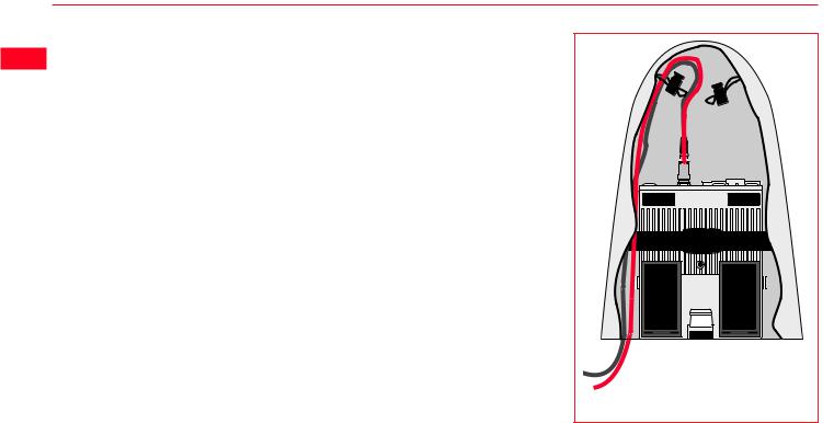
6.Place the Receiver front panel up in the Minipack with the batteries facing outwards. Fasten the strap around the Receiver
7.Connect the GPS Antenna to the Receiver using the two Antenna cables. Connect the longest cable to the Receiver, pass the cable through the cable brake and down through the opening in the bottom corner of the Minipack flap. Draw the required
amount of cable out of the Minipack and tighten the cable brake. Refer to the diagram.
8. Connect the TR500 to the port labelled “Terminal” on the Receiver using the 1.8m cable. Pass it through the opening in the bottom of the Minipack flap, down through a cable brake and then plug into the Receiver. Refer to the diagram.
10. Switch on the system using the ON/OFF button on the Receiver.
 To GPS Antenna
To Terminal
Connecting the TR500 Terminal and GPS
Antenna in the Minipack
2. Set-up and Connection |
30 |
Technical Reference Manual-4.0.0en |
Loading...