

Page 1

Operation & Safety
An Oshkosh Corporation Company
Manual
Original Instructions
Keep this manual with machine at all times.
Models
L2906H, 2906H,
3507H,
619A & 723A
31200567
Revised
November 11, 2010
Page 2

CALIFORNIA PROPOSITION 65
BATTERY WARNING
Battery posts,
terminals and related
accessories contain
lead and lead compounds,
chemical known to the
State of California
to cause cancer and
reproductive harm.
WASH HANDS
AFTER HANDLING!
CALIFORNIA PROPOSITION 65
EXHAUST WARNING
Diesel Engine exhaust and
some of its constituents
are known to the State of
California to cause cancer,
birth defects and other
reproductive harm.
Page 3

Revision Log
Revision Log
April 27, 2009 - A - Original Issue of Manual
November 16, 2009 - B - Revised covers.
August 30, 2010 - C - Revised pages 2-10, 2-11, 3-14, 3-15, 7-4 & 8-1.
November 11, 2010 - D - Revised pages 2-5, 3-14, 3-15 & 3-16.
REVISION LOG
a31200567
Page 4

Read This First
Read This First
This manual is a very important tool! Keep it with the machine at all times.
The purpose of this manual is to provide owners, users, operators, lessors, and
lessees with the precautions and operating procedures essential for the safe and
proper machine operation for its intended purpose.
Due to continuous product improvements, JLG Industries, Inc. reserves the right to
make specification changes without prior notification. Contact JLG Industries, Inc.
for updated information.
Operator Qualifications
The operator of the machine must not operate the machine until this manual has
been read, training is accomplished and operation of the machine has been
completed under the supervision of an experienced and qualified operator.
Operation within the U.S.A. requires training per OSHA 1910.178.
Operators of this equipment must possess a valid, applicable driver’s license, be in
good physical and mental condition, have normal reflexes and reaction time, good
vision and depth perception and normal hearing. Operator must not be using
medication which could impair abilities nor be under the influence of alcohol or any
other intoxicant during the work shift.
In addition, the operator must read, understand and comply with instructions
contained in the following material furnished with the telehandler:
• This Operation & Safety Manual
• Telehandler Safety Manual (as required)
• All instructional decals and plates
• Any optional equipmen t instr uctions furnished
The operator must also read, understand and comply with all applicable Employer,
Industry and Governmental rules, standards and regulations.
Modifications
Any modification to this machine must be approved by JLG.
b 31200567
Page 5

Read This First
This product must comply with all safety related bulletins. Contact JLG Industries,
Inc. or the local authorized JLG representative for information regarding safetyrelated bulletins which may have been issued for this product.
JLG Industries, Inc. sends safety related bulletins to the owner of record of this
machine. Contact JLG Industries, Inc. to ensure that the current owner records are
updated and accurate.
JLG Industries, Inc. must be notified immediately in all instances where JLG
products have been involved in an accident involving bodily injury or death of
personnel or when damage has occurred to personal property or the JLG product.
FOR:
• Accident Reporting and Product Safety Publications
• Current Owner Updates
• Questions Regarding Product Applications and Safety
• Standards and Regulations Compliance Information
• Questions Regarding Product Modifications
CONTACT:
Product Safety and Reliability Department
JLG Industries, Inc.
13224 Fountainhead Plaza
Hagerstown, MD 21742
USA
or Your Local JLG Office
(Addresses on back cover)
In USA
Toll Free: 1-877-JLG-SAFE (1-877-554-7233)
Outside USA
Phone: +1-717-485-6591
E-mail
ProductSafety@JLG.com
c31200567
Page 6

Read This First
Other Publications Available
Service Manual......................................... ................................. ...... ..........31200568
Illustrated Parts Manual....................................... ...... ................................3120 056 6
Note: The following standards may be referenced in this manual:
ANSI is compliant to ANSI/ITSDF B56.6
AUS is compliant to AS 1418.19
CE is compliant to EN1459
Refer to the machine Serial Number Plate to identify the applicable compliance
standard.
d 31200567
Page 7

Table of Contents
TABLE OF CONTENTS
Revision Log
Read This First
Operator Qualifications ......................................................b
Modifications......................................................................b
Other Publications Available..............................................d
Table of Contents
Section 1 - General Safety Practices
1.1 Hazard Classification System..............................................1-1
Safety Alert System and Safety Signal Words................1-1
1.2 General Precautions............................................................1-1
1.3 Operation Safety..................................................................1-2
Electrical Hazards...........................................................1-2
Tip Over Hazard..............................................................1-3
Travel Hazard ............................................. ...... ....... ...... .1-6
Load Falling Hazard........................................................1-7
Lifting Personnel .............................................................1-8
Driving Hazards on Slopes .............................................1-9
Pinch Points and Crush Hazards..................................1-10
Fall Hazard....................................................................1-12
Chemical Hazards.........................................................1-13
Table of Contents
Section 2 - Pre-Operation and Inspection
2.1 Pre-Operation Check and Inspection...................................2-1
2.2 Safety Decals.......................................................................2-3
L2906H, 2906H & 3507H................................................2-3
619A & 723A........ ...... ....... ...... ....... ...... ....... ...... ....... .......2-6
2.3 Walk-Around Inspection.....................................................2-10
2.4 Warm-Up and Operational Checks....................................2-12
Warm-Up Check ...........................................................2-12
Operational Check ........................................................2-12
2.5 Operator Cab.....................................................................2-13
2.6 Windows ............................................................................2-14
Cab Door Window (if equipped)....................................2-14
Section 3 - Controls and Indicators
3.1 General................................................................................3-1
3.2 Controls ...............................................................................3-2
Instrument Panel.. ...... ....... ...... ....... ...... ....... ...... ....... ...... .3-4
Display Screen................................................................3-6
Keypad............................................................................3-8
Ignition ..........................................................................3-10
i31200567
Page 8

Table of Contents
Park Brake.................................................................... 3-11
Parking Procedure........................................................ 3-11
Transmission Control Lever.......................................... 3-12
Load Stability Indicator - LSI
(L2906H, 2906H & 3507H)........................................... 3-14
Steering Column Adjuster............................................. 3-17
Joystick......................................................................... 3-18
Front and Side Console Switches ................................ 3-22
Accessory Control Lever (L2906H, 2906H & 3507H)... 3-24
Accessory Control Lever (619A & 723A, if equipped)..3-25
3.3 Anti Theft........................................................................... 3-26
3.4 Steer Modes...................................................................... 3-27
Manual Steering Alignment Mode Change................... 3-27
Rear Wheel Assisted Steering Alignment
Mode Change............................................................... 3-28
All Wheel Assisted Steering Alignment
Mode Change (if equipped).......................................... 3-29
3.5 Operator Seat.................................................................... 3-30
Adjustments.................................................................. 3-30
Seat Belt.......................................................................3-32
3.6 Boom Extension Indicators................................................ 3-33
Section 4 - Operation
4.1 Engine................................................................................. 4-1
Starting the Engine......................................................... 4-1
Battery Boosted Starting................................................. 4-2
Normal Engine Operation........ ...... ....... ...... ....... ...... ....... 4-3
Shut-Down Procedure .................................................... 4-3
4.2 Operating with a Non-Suspended Load .............................. 4-4
Lift Load Safely............................................................... 4-4
Picking Up a Load ......................... ....... .......................... 4-4
Transporting a Load ................ ...... ....... ...... .................... 4-5
Leveling Procedure......................................................... 4-5
Placing a Load................................................................ 4-6
Disengaging a Load........................................................ 4-6
4.3 Operating with a Suspended Load...................................... 4-7
Lift Load Safely............................................................... 4-7
Picking Up a Suspended Load....................................... 4-7
Transporting a Suspended Load .................................... 4-8
Leveling Procedure......................................................... 4-8
Placing a Suspended Load............................................. 4-9
Disengaging a Suspended Load .................................... 4-9
ii 31200567
Page 9

4.4 Road Operation (L2906H, 2906H & 3507H)......................4-10
4.5 Loading and Securing for Transport ..................................4-11
Tiedown ........................................................................4-11
Lifting ............................................................................4-12
Section 5 - Attachments and Hitches
5.1 Approved Attachments ........................................................5-1
5.2 Unapproved Attachments ....................................................5-1
5.3 Telehandler/Atta chmen t/For k Capacity..... ....... ...... ....... ...... .5-2
5.4 Use of the Capacity Chart....................................................5-3
Capacity Indicator Locations...........................................5-3
Sample Capacity Chart ...................................................5-4
Example..........................................................................5-5
5.5 Attachment Installation ........................................................5-7
JLG Quick Attach............................................................5-7
JD Quick Attach ............................................................5-10
5.6 Hydraulic Operated Attachment.........................................5-12
5.7 Adjusting/Moving Forks......................................................5-13
5.8 Attachment Operation........................................................5-14
Carriage w/Forks...........................................................5-16
Side Tilt Carriage (619A & 723A)..................................5-18
Side Shift Carriage (L2906H, 2906H & 3507H) ............5-20
Side Shift/Fork Positioning Carriage (723A) .................5-22
Fork Mounted Hook ......................................................5-24
Fork Extension (L2906H, 2906H & 3507H) ..................5-26
Truss Boom...................................................................5-28
Carriage w/Round Fork.................................................5-29
Bale Handler .................................................................5-30
Bucket...........................................................................5-32
Multi-Purpose Bucket....................................................5-34
Grapple Bucket .............................................................5-36
Concrete Bucket (L2906H, 2906H & 3507H)................5-38
Personnel Work Platform (619A & 723A) .....................5-40
5.9 Hitches...............................................................................5-42
Pin Hitch - CUNA C (L2906H, 2906H & 3507H)...........5-42
Pin Hitch - CUNA D2 (L2906H, 2906H & 3507H).........5-43
Pin Hitch........................................................................5-44
Auto Hitch .....................................................................5-45
Piton Frame and Auto Hitch
(L2906H, 2906H & 3507H) ...........................................5-46
Hydraulic Hitch..............................................................5-47
Table of Contents
iii31200567
Page 10

Table of Contents
Section 6 - Emergency Procedures
6.1 Towing a Disabled Product ................................................. 6-1
Moving Short Distances........... ...... ....... ...... ....... ...... ....... 6-1
Moving Longer Distances..................... ...... .................... 6-1
6.2 Emergency Lowering of Boom ............................................ 6-2
6.3 Emergency Exit from Enclosed Cab.................................... 6-2
Section 7 - Lubrication and Maintenance
7.1 Introduction.......................................................................... 7-1
Clothing and Safety Gear ............................................... 7-1
7.2 General Maintenance Instructions....................................... 7-2
7.3 Service and Maintenance Schedule.................................... 7-3
10, 1st 50 & 50 Hour Maintenance Schedule................. 7-3
1st 150, 250 & 500 Hour Maintenance Schedule........... 7-4
1500 Hour Maintenance Schedule................................. 7-5
7.4 Lubrication Schedules......................................................... 7-6
10 Hour Lubrication Schedule........................................ 7-6
50 Hour Lubrication Schedule........................................ 7-7
7.5 Operator Maintenance Instructions ..................................... 7-8
Fuel System.................................................................... 7-8
Air Intake System ......................................................... 7-10
Engine Oil..................................................................... 7-12
Hydraulic Oil................................................................. 7-13
Tires.............................................................................. 7-14
Brake System ............................................................... 7-17
Engine Cooling System ................................................ 7-18
Battery.......................................................................... 7-19
Windshield Washer System (if equipped)..................... 7-20
Section 8 - Additional Checks
8.1 General................................................................................ 8-1
8.2 Load Stability Indicator Test (L2906H, 2906H & 3507H) .... 8-1
Section 9 - Specifications
9.1 Product Specificatio ns..... ...... ....... ...... ....... ...... ....... ...... ....... 9-1
Capacities....................................................................... 9-1
Tires................................................................................ 9-2
Performance................................................................... 9-3
Dimensions..................................................................... 9-4
Declaration of Vibration (CE).......................................... 9-6
Noise Emission Level (CE)............................................. 9-6
Index
Inspection, Maintenance and Repair Log
iv 31200567
Page 11

Section 1 - General Safety Practices
DANGER
OW0010
WARNING
OW0021
CAUTION
OW0031
SECTION 1 - GENERAL SAFETY PRACTICES
1.1 HAZARD CLASSIFICATION SYSTEM Safety Alert System and Safety Signal Words
DANGER indicates an imminently hazardous situation which, if not avoided, will
result in death or serious injury.
WARNING indicates a potentially hazardous situation which, if not avoided, could
result in death or serious injury.
CAUTION indicates a potentiality hazardous situation which, if not avoided, may
result in minor or moderate injury.
1.2 GENERAL PRECAUTIONS
WARNING
Before operation, read and understand this manual. Failure to comply with the
safety precautions lis ted in thi s m anu al c oul d res ult in ma ch ine dam age , prop erty
damage, personal injury or death.
1-131200567
Page 12

Section 1 - General Safety Practices
OW0040
10 FT
(3 M)
1.3 OPERATION SAFETY Electrical Hazards
• This machine is not insulated and does not provide protection from contact or
being near electrical current.
• NEVER operate the telehandler in an area where overhead power lines,
overhead or underground cables, or other power sources may exist without
ensuring the appropriate power or utility company de-energizes the lines.
• Always check for power lines before raising the boom.
• Follow employer, local and governmental regulations for clearance from
powerlines.
1-2 31200567
Page 13
Section 1 - General Safety Practices
OW0050
OW0080
OW0100
4 FT
(1,2 M)
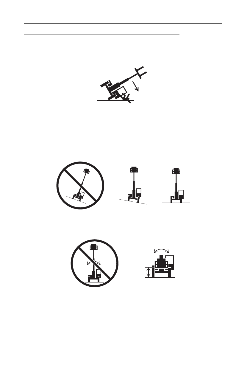
Tip Over Hazard
General
• For additional load requirements, refer to the appropriate capacity chart.
• Never use an attachment without the appropriate JLG approved capacity chart
installed on the telehandler.
• Understand how to properly use the capacity charts located in cab.
• DO NOT exceed rated lift capacity.
• Be sure that the ground conditions are able to support the machine.
• DO NOT rai se boom unles s frame is lev el (0 degrees ), unless othe rwise not ed on
capacity chart.
• DO NOT level machine with boom/attachment above 1,2 m (4 ft).
(AUS - DO NOT level machine with load more than 300 mm (11.8 in) above
ground surface.)
1-331200567
Page 14

Section 1 - General Safety Practices
OH2291
OH20911
OH2221
• MAINTAIN proper tire pressure at all times. If proper tire pressures are not
maintained, this machine cou ld tip ov er.
• Refer to manufacturer’s specifications for proper fill ratio and pressure
requirements for tires equipped with ballast.
• Always wear the seat belt.
• Keep head, arms, han ds, le gs and al l ot her bo dy part s inside op erator’s ca b at al l
times.
If the telehandler starts to tip over:
• DO NOT JUMP
• BRACE YOURSELF and STAY WITH THE MACHINE
• KEEP YOUR SEAT BELT FASTENED
•HOLD ON FIRMLY
• LEAN AWAY FROM THE POINT OF IMPACT
1-4 31200567
Page 15
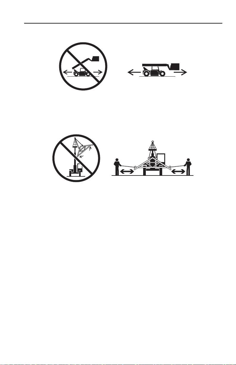
Non-Suspended Load
OW0060
OW0150
• DO NOT drive with boom raised.
Suspended Load
Section 1 - General Safety Practices
• Tether suspended loads to restrict movement.
• DO NOT raise the load more than 300 mm (11.8 in) above ground surface or the
boom more than 45°.
• Weight of all rigging (slings, etc.) must be included as part of load.
• Start, travel, turn and stop slowly to prevent load from swinging.
• When driving with the boom raised, DO NOT exceed walking speed.
• Beware of wind. Wind can cause a suspended load to swing and cause
dangerous side loads - even with tag lines.
• DO NOT a ttemp t to us e teleh andle r frame-l eveling to com pens ate for load sw ing.
• Keep heavy part of load closest to attachment.
• Never drag the load; lift vertically.
1-531200567
Page 16

Section 1 - General Safety Practices
OAL2030
2-Wheel Front Steer 4-Wheel Circle Steer 4-Wheel Crab Steer
Tr avel Hazard
• Steering characteristics differ between steer modes. Identify the steer mode
settings of the telehandler being operated.
• DO NOT change steer modes while traveling. Steer modes must be changed
while telehandler is stationary.
• Visually verify proper wheel alignment after each steer mode change.
• Ensure that adequate clearance is provided for both rear tail swing and front fork
swing.
• Look out for and avoid other personnel, machinery and vehicles in the area. Use
a spotter if you do not have a clear view.
• Before moving be sure of a clear path and sound horn.
• When driving, retract boom and keep boom/attachment as low as possible while
maintaining visibility of mirrors and maximum visibility of path of travel.
• Always look in the direction of travel.
• Always check boom clearances carefully before driving underneath overhead
obstructions. Position attachment/load to clear obstacles.
• When driving in high speed, use only front wheel steer (if steering modes are
selectable).
1-6 31200567
Page 17

Section 1 - General Safety Practices
OW0130
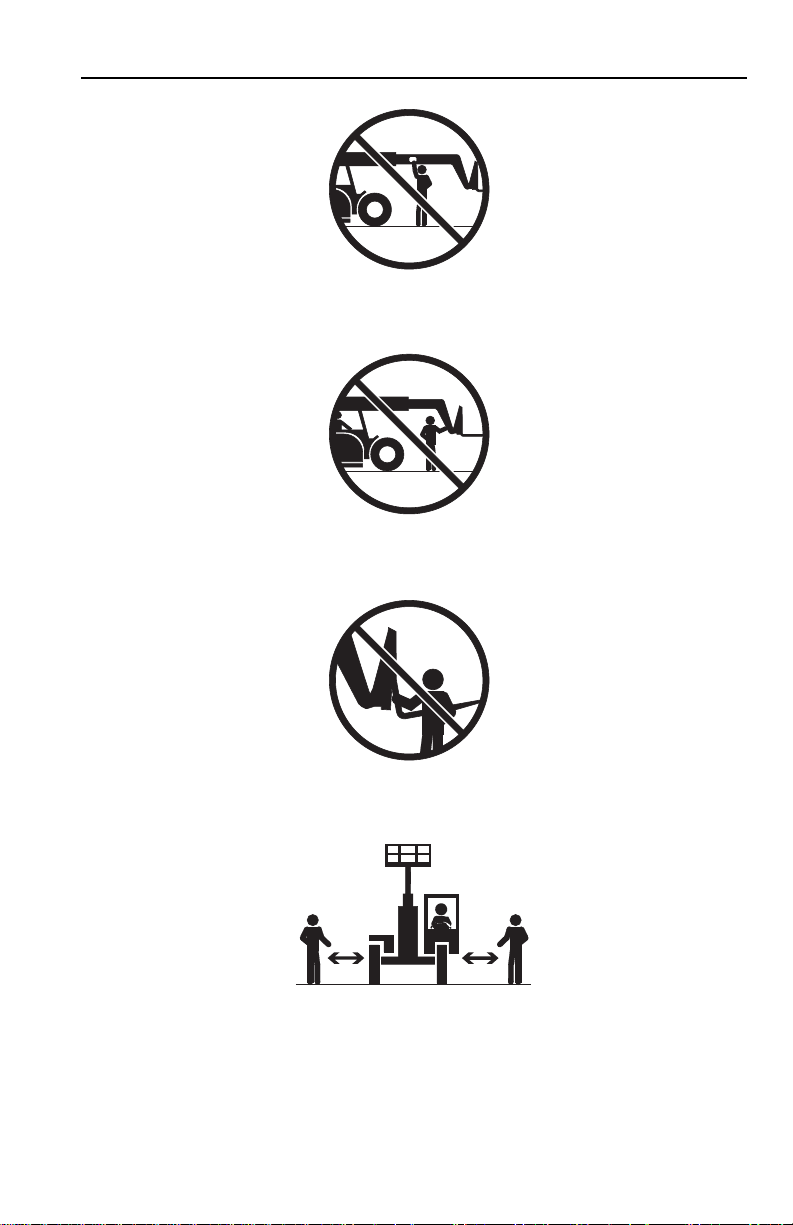
Load Falling Hazard
• Never suspend load from forks or other parts of carriage.
• DO NOT burn or drill holes in fork(s).
• Forks must be centered under load and spaced apart as far as possible.
1-731200567
Page 18

Section 1 - General Safety Practices
OW0170
OW0190
Lifting Personnel
• When lifting personnel, USE ONLY a JLG approved personnel work platform,
with proper capacity chart displayed in the cab.
• DO NOT drive machine from cab when personnel are in platform.
1-8 31200567
Page 19

Section 1 - General Safety Practices
OW0200
Driving Hazards on Slopes
To maintain sufficient traction and braking capabilities, travel on slopes as follows:
• When unloaded, the rear of the mac hine is the “heavy end.” Drive with forks
pointed downhill.
• When loaded, the front of the machine is the “heavy end.” Drive with the forks
pointed uphill.
• For additional travel requirements, refer to the appropriate capacity chart.
• To avoid overspeeding the engine and drivetrain when driving down slopes,
downshift to a lower gear and use the service brake as necessary to maintain a
slow speed. DO NOT shift into neutral and coast downhill.
• Avoid excessively steep slopes or unstable surfaces. To avoid tip over DO NOT
drive across excessively steep slopes under any circumstances.
• Avoid turning on a slope. Never engage “inching” or shift to “Neutral” when going
downhill.
• DO NOT park on a slope.
1-931200567
Page 20

Section 1 - General Safety Practices
OW0210
OW0220
OW0230
Pinch Points and Crush Hazards
Stay clear of pinch points and rotating parts on the telehandler.
• Stay clear of moving parts while engine is running.
• Keep clear of steering tires and frame or other objects.
• Keep clear from under boom.
1-10 31200567
Page 21
Section 1 - General Safety Practices
OW0240
OW0250
OW0260
OW0960
• Keep clear of boom holes.
• Keep arms and hands clear of attachment tilt cylinder.
• Keep hands and fingers clear of carriage and forks.
• Keep others away while operating.
1-1131200567
Page 22

Section 1 - General Safety Practices
OW0280
OW0290
Fall Hazard
• Enter using the proper hand holds and steps provided. Always maintain 3-point
contact when mounting or dismounting. Never grab control levers or steering
wheel when mounting or dismounting the machine.
• DO NOT get o f f th e m ac hi ne until the shutdown procedure on pa ge4-3 has been
performed.
• DO NOT carry riders. Riders could fall off machine causing death or serious
injury.
1-12 31200567
Page 23

Section 1 - General Safety Practices
OW0300
OW0950
Chemical Hazards
Exhaust Fumes
• DO NOT operate machine in an enclosed area without proper ventil ation.
• DO NOT operate the machine in hazardous environments unless approved for
that purpose by JLG and site owner. Sparks from the electrical system and the
engine exhaust can cause an explosion.
• If spark arrestors are required, ensure they are in place and in good working
order.
Flammable Fuel
• DO NOT fill the fuel tank or service the fuel system near an open flame, sparks
or smoking materials. Engine fuel is flammable and can cause a fire and/or
explosion.
Hydraulic Fluid
• DO NOT attempt to repair or tighten any hydra ulic hoses or fittin gs while t he
engine is running or when the hydraulic system is under pressure.
• Stop engine and relieve trapped pressure. Fluid in the hydraulic system is under
enough pressure that it can penetrate the skin.
• DO NOT use your hand to check for leaks. Use a piece of cardboard or paper to
search for leaks. Wear gloves to protect hands from spraying fluid.
1-1331200567
Page 24

Section 1 - General Safety Practices
This Page Intentionally Left Blank
1-14 31200567
Page 25
Section 2 - Pre-Operation and Inspection
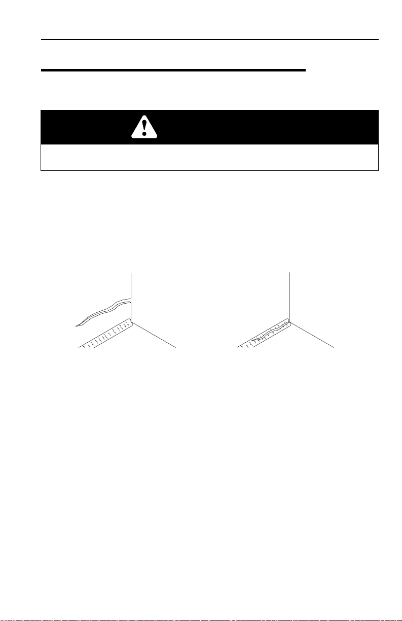
OAH1000
PARENT METAL CRACK WELD CRACK
SECTION 2 - PRE-OPERATION AND INSPECTION
2.1 PRE-OPERATION CHECK AND INSPECTION
Note: Complete all required maintenance before operating unit.
WARNING
FALL HAZARD. Use extreme caution when checking items beyond your normal
reach. Use an approved ladder.
The pre-operation check and inspection, performed at beginning of each work shift
or at each change of operator, should include the following:
1. Cleanliness - Check all surfaces for leaka ge (oil, fuel or battery fluid) or fo reign
objects. Report any leakage to the proper maintenance personnel.
2. Structure - Inspect the machine structure for dents, damage, weld or parent
metal cracks or other discrepancies.
3. Safety Decals - Ensure all safety decals are legible and in place. Clean or
replace as required. See page 2-3 for details.
4. Operation and Safety Manuals - Operation & Safety Manual and AEM Safety
Manual (as required) are located in cab manual holder.
5. Walk-Around Inspection - See page2-10 for details.
6. Fluid Levels - Check fluids, includi ng fu el, hy drau lic oi l, en gi ne oil and coolant.
When adding fluids, refer to Section 7 - Lubrication and Maintenance and
Section 9 - Specifications to determine proper type and intervals. Before
removing filler caps or fill plugs, wipe all dirt and grease away from the ports. If
dirt enters these ports, it can severely reduce component life.
7. Attachments/Accessories - Ensure correct capa cit y cha rts are ins tal led on
the telehandler. If provided, reference the Operation & Safety Manual of each
attachment or accessory installed for specific inspection, operation and
maintenance instructions.
2-131200567
Page 26

Section 2 - Pre-Operation and Inspection
8. Oper ational Check - Once the walk-around inspection is complete, perform a
warm-up and operational check (see page 2-12) of all systems in an area free
of overhead and ground level obstructions. See Section 3 - Controls and
Indicators for more specific operating instructions.
WARNING
If telehandler does not operate properly, immediately bring machine to a stop,
lower boom and attachm ent to grou nd and st op th e engine . Deter mine c ause an d
correct before continued use.
2-2 31200567
Page 27
Section 2 - Pre-Operation and Inspection
OAH1170
8006038
8006038
8005617
(3507H)
8005617
8005616
8005616
(3507H)
8005617
(3507H)
8005617
8005616
8005616
(3507H)
8005675
8005675
8005671
(L2906H)
8005671
8008657
8008657
8003198 8003198
8008657
8008657
8005671
8005671
(2906H
& 3507H)
8005617
(L2906H
& 2906H)
8005617
8005616
8005616
(L2906H
& 2906H)
8005617
8005617
1705980
L
WA
06
dB
1
1705980
8009377
35
8003198
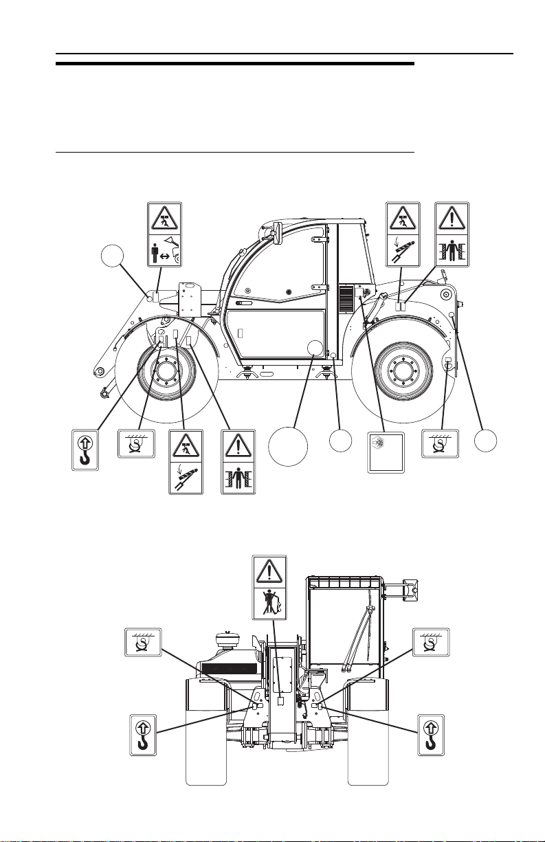
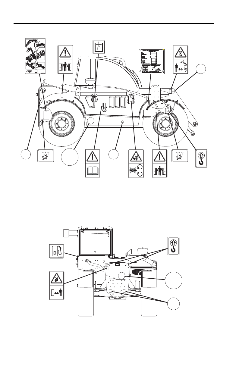
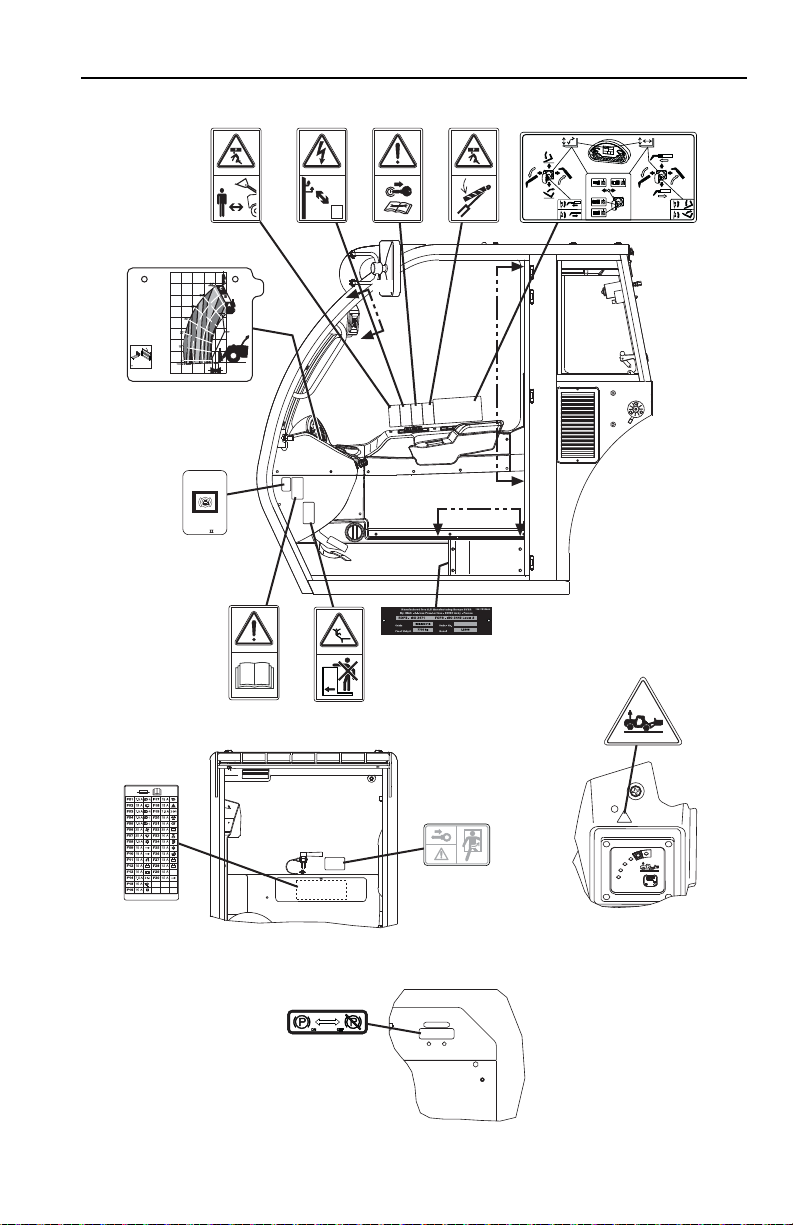
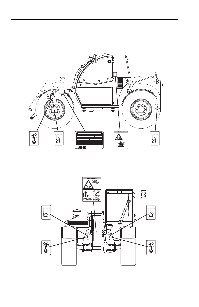
2.2 SAFETY DECALS
Ensure all DANGER, WARNING, CAUTION and instructional decals and proper
capacity charts are legible and in place. Clean and replace as required.
L2906H, 2906H & 3507H
2-331200567
Page 28
Section 2 - Pre-Operation and Inspection
OAH1180
8005616
8005616
3931579
8006612
8006612
8009815
8009377
35
80031988003198
8008657
8008657
8005617
(L2906H
& 2906H)
8005617
8005616
8005616
(L2906H
& 2906H)
8005617
8005617
8009377
35
8008657
8008657
8005675
8005675
8003198
8005670
8005670
8005869
8005869
8009816
8009816
1001094795
1706227
2-4 31200567
Page 29
Section 2 - Pre-Operation and Inspection
OAH1191
1706209
8005870
8005870
12
1001112333
1001112333
1001111863
1001111863
8005671
8005671
8005672
8005672
8005673
8005672
8005674
8005674
2447967
OIL
ATF
Dexron
D
2447 967
8008651
8005674
8005670
8005670
1001112405
(L2906H)
1001112403
(2906H & 3507)
XXX XX MAX
XX
XXXX
XXXXXXXXXX
XXXXXXXX
XXXXXXX
XX
XXXXXX
X
X
X
X
X
X
X
X
X
X
XXXX XX
XXXX XX
XXXX XX
XXXX XX
XXXX XX
XXXX XX
XXXX XX
XXXX XX
1001127546
1001127546 A
VIEW A-A
VIEW B-B
BB
A
A
CAPACITY
CHARTS
VIEW C-C
(S/N 1160005989 & AFTER
INCLUDING1160005189,
1160005314 & 1160005414)
C
C
2-531200567
Page 30
Section 2 - Pre-Operation and Inspection
OAH1200
1702300
(723A)
1702300
1701500
(723A)
1701500
1702300
(723A)
1702300
1701500
(723A)
1701500
1706298
1706298A
Model
SerialNumber
YearOfManufacture
MaximumWeightWithout Attachments (lbs/kg)
MaximumCapacity(lbs/kg)
°Referto load capacity chart for truck with attachment, and individual load ratings stamped
onforks,if equipped. Use lowest capacity of all ratings.
Asreleasedfrom factory this truck meets specifications in ASME B56.6-2002 Part III.
Oneormore of the following patents may apply to this truck; U.S. Nos. 4,954,041 6,349,969
5,639,1195,813,6975,230,399 5,052,532. Other patents pending.
1706910A
R
Manufacturedby
IndustrieterreinOudeBunders 1034, Breitwaterstraat 12
3630Maasmechelen- Belgium
JLGManufacturing Europe BVBA
1706910
1702300
(619A)
1702300
1701500
(619A)
1701500
1702300
1702300
Riders
could
falloff
machine
causing
deathor
serious
injury.
NoRiders
1706835A
1706835
619A & 723A
2-6 31200567
Page 31

OAH1210
8009815
1701500
1701500
1702300
(619A)
1702300
1701500
(619A)
1701500
WARNING
!
EXPLOSION/FIREHAZARD
Donot use starting fluid.
Thisunit is equipped with an
airintake heater or glow plugs.
Failureto follow instructions could
resultin deathor seriousinjury.
1704972C
1704972
1706297A
1706297
1702300
1702300
1001094795
1701504
1701504
1706301
1706301A
Section 2 - Pre-Operation and Inspection
2-731200567
Page 32

Section 2 - Pre-Operation and Inspection
OAH1220
1706209
8005870
8005870
12
1001112333
1001112333
1001111863
1001111863
2447967
OIL
ATF
Dexron
D
2447 967
1001112403
1707078
Keepothers
awaywhile
operating.
WARNING
RUN-OVER
HAZARD
c
ouldcause
deathor
serious
injury.
LOWERINGBOOM or
FALLINGLOAD
cancrush causing death
orserious injury.
CONTACTING
POWERLINES
willresult in death
orserious injury.
DONOT place
machineor load
within10 feet (3m)
ofpower lines.
MACHINE
ROLL-AWAY
couldcause
deathor
seriousinjury.
JUMPINGOFF
ofa tipping
machinecould
resultin
deathor
seriousinjury.
1707078A
Fasten
seat
belt.
Operatormust be trained and
mustread and understand
allcapacity charts, operator
andsafety manuals.
XXX XX MAX
XX
XXXX
XXXXXXXXXX
XXXXXXXX
XXXXXXX
XX
XXXXXX
X
X
X
X
X
X
X
X
X
X
XXXX XX
XXXX XX
XXXX XX
XXXX XX
XXXX XX
XXXX XX
XXXX XX
XXXX XX
VIEW A-A VIEW B-B
BB
A
A
CAPACITY
CHARTS
2-8 31200567
Page 33

Section 2 - Pre-Operation and Inspection
This Page Intentionally Left Blank
2-931200567
Page 34

Section 2 - Pre-Operation and Inspection
OAH1231
1
2
3
4
5
6
6
5
5
5
12
7
8
9
14
16
17
18
19
20
21
10
11
13
15
2.3 WALK-AROUND INSPECTION
Begin your walk-around inspection at item 1, as noted below. Continue to your right
(counterclockwise when viewed from top) checking each item in sequence.
INSPECTION NOTE: On all components, make sure there are no loose or missing
parts, that they are securely fastened and no visible leaks or excessive wear exists
in addition to any other criteria mentioned. Inspect all structural members including
attachment for cracks, excessive corrosion and other damage.
1. Boom Sections and Lift, Tilt, Extend/Retra ct, Compensating (Slave) Cylin ders
• Check front, top, side and rear wear pads for presence of grease.
• Pivot pins secure; hydraulic hoses undamaged, not leaking.
2. Wheel Chock (L2906H & 2906H, if equipped) - See inspection note.
3. Boom Prop
4. Wheel/Tire Assembly - Properly inflated and secured; no loose or missing lug
nuts. Inspect for worn tread, cuts, tears or other discrepancies.
2-10 31200567
(2906H & 3507H)(619A & 723A, if equipped) - See inspection note.
-
Page 35

Section 2 - Pre-Operation and Inspection
5. Work Lights (if equipped) - Clean and undamaged.
6. Mirrors
7. Cab and Electrical -
8. Wheel/Tire Assembly
9. Boom Prop
10. Rear Axle
11. Main Control Valve
12. Rear Mirror
13. LSI Sensor (L2906H, 2906H & 3507H) - See inspection note.
14. Wheel/Tire Assembly
15. Boom Sensor
- Clean and undamaged.
• General appearance; no visible damage.
• Frame level indicator and window glass undamaged and clean.
• Gauges, switches, joystick, foot controls, park brake and horn operational.
• Fire Extinguisher (723A, if equipped) charged, undamaged and clean.
• Check seat belt for damage, replace belt if frayed or cut webbing, damaged
buckles or loose mounting hardware.
- Properly inflated and secured; no loose or missing lug
nuts. Inspect for worn tread, cuts, tears or other discrepancies.
(L2906H) - See inspection note.
- Steer cylinders undamaged, not leaking; pivot pins secure;
hydraulic hoses undamaged, not leaking.
- See inspection note.
(if equipped) - Clean and undamaged.
- Properly inflated and secured; no loose or missing lug
nuts. Inspect for worn tread, cuts, tears or other discrepancies.
(L2906H, 2906H & 3507H S/N 1160005989 & After including
11 60005189, 1160005314 & 1160005414) - See inspection note.
16. Air Precleaner - Check and clean as required.
17. Engine Compartment -
• Drive belts, check condition and replace as required.
• Engine mounts - See inspection note.
• Battery cables tight, no visible damage or corrosion.
• Engine cover closed and properly secured.
18. Wheel Chock
19. Wheel/Tire Assembly
nuts. Inspect for worn tread, cuts, tears or other discrepancies.
20. Front Axle
undamaged, not leaking.
21. Attachment
(3507H, if equipped) - See inspection note.
- Properly inflated and secured; no loose or missing lug
- Steer cylinders undamaged, not leaking; hydraulic hoses
- Properly installed, see “Attachment Installation” on page 5-7.
2-1131200567
Page 36

Section 2 - Pre-Operation and Inspection
2.4 WARM-UP AND OPERATIONAL CHECKS Warm-Up Check
During warm-up period, check:
1. Heater, defroster and windshield wiper (if equipped).
2. Check all lighting systems (if equipped) for proper operation.
3. Adjust mirror(s) for maximum visibility.
WARNING
CUT/CRUSH/BURN HAZARD. Keep engine cover closed while engine is
running.
Operational Check
When engine warms, perform an operational check:
1. Service brake and parking brake operation.
2. Forward and reverse travel.
3. Each gear.
4. Steering in both directions with engine at low idle (steering lock to lock will not
be reached). Check in each steering mode.
5. Horn and back-up alarm. Must be audib le from ins ide operato rs cab with en gine
running.
6. All joystick functions - operate smoothly and correctly.
7. Perform any additional checks described in Section 8.
2-12 31200567
Page 37

Section 2 - Pre-Operation and Inspection
2.5 OPERATOR CAB
The telehandler is equipped with an open or enclosed ROPS/FOPS cab.
WARNING
Never operate telehandler unless the overhead guard and cab structure are in
good condition. Any modification to this machine must be approved by JLG to
assure compliance with ROPS/FOPS certification for this cab/machine
configuration. If damaged, the CAB CANNOT BE REPAIRED. It must be
REPLACED.
2-1331200567
Page 38

Section 2 - Pre-Operation and Inspection
1
2
3
4
OAH1240
2.6 WINDOWS
Keep all windows and mirrors clean and unobstructed.
Cab Door Window (if equipped)
• Cab doo r (1) must be closed during operation.
• During operation the cab door window (2) must either be latched open or closed.
• Open the cab door window and secure it in the latch (3).
• Press the release button in side t he cab o r pu ll lev er (4) o utsid e the ca b to unla tch
the window .
2-14 31200567
Page 39

Section 3 - Controls and Indicators
SECTION 3 - CONTROLS AND INDICATORS
3.1 GENERAL
This section provides the necessary information needed to understand control
functions.
Note: The manufacturer has no direct control over machine application and
operation. The user and operator are responsible for conforming with good safety
practices.
3-131200567
Page 40

Section 3 - Controls and Indicators
OAH1250
1
2
3
4
5
6
7
8
9
11
12
13
14
15
16
17
10
3.2 CONTROLS
1. Park Brake: See page 3-11.
2. Accelerator Pedal
speed.
3. Service Brake Pedal
speed.
4. Ignition Switch
5. Front Console Switches
6. Adjustable Steering Column
7. Transmission Control Lever: See page 3-12.
8. Frame Level Indicator
condition of the telehandler.
9. Engine Oil Temperature Gauge
operating temperatur e.
3-2 31200567
: Pressing down the pedal increases engine and hydraulic
: The further the pedal is depressed, the slower the travel
: Key activated. See page 3-10.
: See page 3-22.
: Enables operator to determine the left to right level
: See page 3-17.
(723A, if equipped): Indicates engine oil
Page 41

Section 3 - Controls and Indicators
10. Steering Wheel: Turning the steering wheel to the left or right steers the
machine in the corresponding direction. Three steering modes are available.
See “Steer Modes” on page 3-27.
11. Instrument Panel
12. LSI Indicator
13. Accessory Control Lever (if equipped): See page 3-24.
14. Keypad
15. Joystick
16. Side Console Switches: See page 3-22.
17. Hydraulic Hitch Safety Hook Release
on hydraulic hitch. See page 5-47.
: See page 3-8.
: See page 3-18.
: See page 3-4.
(L2906H, 2906H & 3507H): See page 3-14.
(if equipped): Pull to relea se safety ho oks
3-331200567
Page 42

Section 3 - Controls and Indicators
OAH1260
1
2
4
6
7
8
9
1011121314151617181920
21
22
23
3
5
Instrument Panel
1. Low Fuel Indicator: Illuminates and buzzer sounds briefly when fuel level is low.
2. Fuel Gauge:
3. Left Turn Signal Indicator: Illuminates when left turn signal is active.
4. Display Screen
5. Right Turn Signal Indicator
6. Engine Te mperature Gauge: Indicates engine operating temperature.
7. Engine Temperature Warni ng Indicator
engine temperature is too high.
8. Continuous Auxiliary Hydrauli cs Indicator
auxiliary hydraulic s are active.
9. Trailer Turn Signal Indicator: Illuminates when trailer turn signal is activated.
10. High Beam Indicator: Illuminates when high beam lights are on.
11. Anti Theft Indicator
theft feature is active. Enter anti theft code, see page 3-26.
12. Maintenance Indicator
13. Engine Preheat Indicator: With ignition key in position II, illuminates up to twel ve
14. Park B rake Indicator
15. System Distress Indicator
3-4 31200567
maintenance is required.
seconds to indicate engine preheat is active.
and engine faults exist.
Indicates amount of fuel in fuel tank.
: See page 3-6.
: Illuminates when right turn signal is active.
: Illuminates and buzzer sounds when
: Illuminates when continuous
: Illuminates and buzzer sounds briefly at start-up when anti
: Illuminates and buzzer sounds briefly when
: Illuminates when park brake is applied. See page 3-11.
: Illuminates and buzzer sounds when critical machine
Page 43

Section 3 - Controls and Indicators
16. Engine Fault Critical Indicator: Illuminates and buzzer sounds when a critical
engine fault exists.
17. Engine Fault Warning Indicator
operating outside the normal range.
18. Air Filter Restriction Indicator: Illuminates and buzzer sounds briefly when air
filter(s) require maintenance.
: Illuminates and buzzer sounds when engine is
19. Engine Oil Pressure Indicator
pressure is too low.
20. Battery Charge Indicator
system is not functioning properly.
21. Trailer Park Brake Indicator: Illuminates when trailer park brake is applied.
22. Steer ing Pressur e Indicator: Illuminates and buzzer sounds when steering
pressure is too low.
23. Hydraulic Filter Restriction Indicator: Illuminates and buzzer sounds briefly
when hydraulic filter requires maintenance.
: Illuminates and buzzer sounds when engine oil
: Illuminates when battery is at low charge or charging
NOTICE
EQUIPMENT DAMAGE. When the engine fault, system distress or a red
indicator illuminates (except park brake), immediately bring machine to a stop,
lower boom and attachm ent to grou nd and st op the eng ine . Deter mine caus e and
correct before continued use.
Note: All indicators (except high beam and turn signals) perform a bulb check at
system start up.
3-531200567
Page 44

Section 3 - Controls and Indicators
OAH1270
8
2
3
4
5
6
7
00
0000
0000
00
F2
RPM
km/h
100
0
00
0000
0000
RPM
km/h
1
DISPLAY SHOWN WITH CONTINUOUS
AUXILIARY HYDRAULICS ACTIVE
DISPLA Y SHOWN WITH ANTI THEFT
ACTIVE AT SYSTEM START
Display Screen
1. Joystick Mode: Displays current joystick mode. Joystick mode can be changed
by the machine ow ner in Opera tor Tools Menu (level 2 pas swor d requi red). See
Service Manual for information.
a. Loader Joystick Pattern - Displays loader joystick pattern icon on left when
active. See page 3-20.
b. Lift Joystick Pattern - Displays lift joystick pattern icon on right when active.
See page 3-18.
2. Speed
3. Driving Direction and Gear
4. Engine Speed: Displays engine speed in revolutions per minute (rpm).
5. Operating Hours: Displays total hours of telehandler operation.
6. Boom Angle
7. Continuous Auxiliary Hydraulics and Steering Mode Change
8. Anti Theft Code Entry
3-6 31200567
: Telehandler travel speed displayed in kilometers per hour (km/h) or
miles per hour (m/h). Travel speed will flash and buzzer sounds if maximum
travel speed is exceeded.
: Displays current driving condition.
a. Direction - Forward (F), Neutral (N) or Reverse (R).
b. Gear - First (1) or Second (2).
: Displays boom angle in degrees. 0 degrees indicates horizontal.
:
a. Continuous Auxiliary Hydraulics - Displays flow value (-100% to +100%)
when continuous auxiliary hydraulics is activated. See Section
5 - Attachments and Hitches for details.
b. Steering Mode Change - Assists with steering mode change. See “Steer
Modes” on page3-27 for details.
: If active, the four digit code must be ente red after system
start. See “Anti Theft” on page 3-26.
Page 45

Section 3 - Controls and Indicators
OAH2000
MENU:
HELP: PRESS ENTER
9
9. Menus: Menus display fault code s and other mach ine informat ion while allow ing
modification of some operating parameters. Depress and hold the C and OK
buttons on the keypad to access menus.
a. Help - Displays active fault code. Depress OK button again and use keypad
arrows to cycle through the last 25 fault code s. Active faul ts are denoted with
an asterisk.
b. Operator Tools - Speed, Temperature and Oil Pressure units, Steering
Change Mode and Tires can be modified by the operator. Customer or
Service level access code required to modify additional items.
• Machine Speed - Select units (km/h or m/h) to be displayed.
• Engine Temperature - Select units (Celsius or fahrenheit) to be
displayed.
• Steering Alignment Mode - Selec t mod e (manual, rear wheel as sisted or
all wheel assisted, if equipped) to be used when changing steering
modes, see page 3-27.
• Tires - Select tire size installed on machine.
c. Personalities - View performance parameters. Customer or Service level
access code required to modify parameters.
d. Access Level - Code entry determines access level.
• Operator (Level 3) - No code required.
• Customer (Level 2) - See Service Manual for information.
• Service (Level 1) - Manufacturer service representative only.
e. Diagnostics - View diagnostic information.
f. System Test - Performs test of all system inputs and outputs.
g. Machine Setup - View machine configurations. Service level access code
required to modify con figurations.
h. Calibrations - Customer or Service level access code required.
3-731200567
Page 46

Section 3 - Controls and Indicators
OZ2361
2 31
4
5 6 7
Keypad
1. C (Clear or escape): Use in conjuction with display screen. Returns user
interface one level during navigation. If at top level menu, depress and hold for
one second to exit.
2. Up/Down Arrows
selections and change adjustable values.
3. OK
(Enter): Use in conjuction with display screen. Confirms user interface
inputs.
4. Steer Mode
Steer and 4-Wheel Crab Steer. Illuminated LED indicates current steer mode.
See page 3-27.
Note: If machine is shut-dow n during st eer mode chan ge, it mus t be compl eted
at restart.
5. LSI Override
function cut-out. LED flashes while activated. Depress and hold up to 30
seconds while operating joystick to momentarily disable the automatic function
cut-out.
: Use in conjuction with display screen. Navigate menu
: Three steer modes available : 4-Whe el Circle Steer, 2-Wheel Front
(L2906H, 2906H & 3507H): Momentarily disables the automatic
WARNING
TIP OVER HAZARD. Exceeding lift capacity o f th e tel eh and ler cou ld dam ag e the
equipment and/or cause tip over.
6. Bucket Mode
function.
7. Joystick Function: LED lit while activated. Boom, auxiliary hydraulics and
outrigger functions are enabled. Deactivate this function before traveling on
public roads. See “Road Operation (L2906H, 2906H & 3507H)” on page 4-10.
Note: All LEDs perform a bulb check at system start up.
: LED lit while activated. Increases response to attachment tilt
3-8 31200567
Page 47

Section 3 - Controls and Indicators
This Page Intentionally Left Blank
3-931200567
Page 48

Section 3 - Controls and Indicators
OAH1280
0
I
II
III
Ignition
• Position 0 - Engine off. Key is removable.
• Position I - Voltage available for all electrical functions.
• Position II - Engine preheat at temperatures below 32° C (90° F). Hold position
up to 12 seconds. Position II is a momentary position and will return to position I
when released.
• Position III - Engine start. In the event the engine does not start, rotate key to
position 0 then back to position III to re-engage the starter.
3-10 31200567
Page 49

Section 3 - Controls and Indicators
OAH1290
1
2
Park Brake
The park brake lever (1) controls the application and release of the park brake.
• Pull lever back to apply park brake.
• Lift detent ring (2) and push lever forward to release park brake.
WARNING
MACHINE ROLL-AWAY HAZARD. Always move park brake lever to "ON"
position, lower boom to ground and stop engine before leaving cab.
WARNING
CRUSH HAZARD. Turning eng ine of f applies t he park brak e. Applyin g park brak e
or turning engine off while traveling will cause unit to stop abruptly and could
cause load loss. Either may be used in an emergency situation.
Parking Procedure
1. Using service brake, stop telehandler in an appropriate parking area.
2. Follow “Shut-Down Procedure” on page 4-3.
3-1131200567
Page 50

Section 3 - Controls and Indicators
OAH1300
1
N
F
R
Transmission Control Lever
Direction of Travel Selection
Transmission control lever (1) engages forward or revers e travel.
• Push lever forward for forw ard trav el; pul l le ve r rear wa rd fo r revers e tra ve l. M ove
lever to centered position for Neutral.
• Forward or reverse travel can be selected while in any gear.
• When traveling in reverse, the back-up alarm will automatically sound.
• Drive in reverse and turn only at slow rates of speed.
• Do not increase engine spee d with the transmi ssion in forw ard or reverse and th e
service brake depressed in an attempt to get quicker hydraulic performances.
This could cause unexpected machine movement.
WARNING
TIP OVER/CRUSH HAZARD. Bring telehandler to a complete stop before
shifting transmission control lever. A sudden change in direction of travel could
reduce stability and/or cause load to shift or fall.
3-12 31200567
Page 51

Section 3 - Controls and Indicators
OAH1310
2
2nd
1st
OAH1320
3
Gear Selection
Gear selection is located on the twist grip handle (2) of transmission control lever.
• Twist hand grip to select gear.
• Select the appropriate gear for the task being performed. Use a lower gear
when transporting a load. Use a higher gear only when driving unloaded for
longer distances.
• Slow down prior to downshifting.
Horn (619A & 723A)
Horn button (3) is located on the end of transmission control lever.
• Depress button to sound horn.
3-1331200567
Page 52

Section 3 - Controls and Indicators
OAH1330
1
2
3
4
5
6
Load Moment
Indicator
100%
TEST
Load Stability Indicator - LSI (L2906H, 2906H & 3507H)
WARNING
TIP OVER HAZARD. The LSI considers only longitudinal stability limitations,
observe all operating parameters. Failure to follow operating parameters of the
telehandler could damage the equipment and/or cause tip over.
Before S/N 1160005989 excluding 1160005189, 1160005314 & 1160005414
The LSI (1) provides visual and audible indication of forward stability limitations
when machine is static on firm, level surface.
• Green LED (2) will illuminate when LSI power is on.
• When approaching forward stability limitations LEDs progressively illuminate,
green (3), then yellow (4) and finally red (5).
• The warning buzzer sounds as the yellow LED illuminates.
• As the telehandler reaches forward stability limitations and the red LED
illuminates, the automatic function cut-out is activated. Certain functions are
disabled (i.e. boom lift, extend, etc). Retract boom to re-enable functions.
• Test LSI (6) at the beginning of each work shift. See Section 8 - Additional
Checks.
3-14 31200567
Page 53

Section 3 - Controls and Indicators
OAH2092
12
9
10
8
11
7
13
S/N 1160005989 & After including 1160005189, 1160005314 & 1160005414
The LSI (7) provides visual and audible indication of forward stability limitations
when machine is static on firm, level surface.
• Green LED (8) will illuminate when LSI power is on.
• When approaching forward stability limitations LEDs progressively illuminate,
green (9), then orange (10) and finally red (11).
• If the red LED illuminates the warning buzzer also sounds.
The LSI has two modes:
Active Mode
• As the telehandler reaches forward stability limitations and the red LED (11)
illuminates, the automatic function cut-out is activated. All boom, frame level
and outrigger functions are disabled except for boom retract (CE & AUS)
and boom lift (CE). Retract boom to re-enable functions.
• In some instances the LSI system may slow down or stop boom functions if
operated close to forward stability limitations. When LEDs begin to flash,
certain functions can not be operated. Retract boom and/or return the
joystick to neutral position for a short period to allow system to reset and
LEDs to stop flashing before proceeding with operation.
Passive Mode
• The orange LED (13) illuminates when either of the following oc curs:
• The boom is fully retracted.
• The park brake is not applied and transmission control lever is in the
forward or reverse position.
• When approaching forward stability limitations, visual and audible indication
is provided and the automatic function cut-out and/or slow down feature is
disabled.
3-1531200567
Page 54

Section 3 - Controls and Indicators
• Travel in accordance with the requirements set forth in Section 1 - General
Safety Practices.
• Test LSI (12) at the beginning of each work shift. See Section 8 - Additional
Checks.
• When placing a load, ensure axles are not fully steered in either direction.
WARNING
TIP OVER HAZARD. If the green, orange and red LEDs flash and warning
buzzer sounds, retract and lower boom immediately. Determine cause and
correct before continued use.
3-16 31200567
Page 55

Section 3 - Controls and Indicators
OAH1340
7
Steering Column Adjuster
•Follow “Shut-Down Procedure” on page 4-3.
• Turn lever (7) counterclockwise to unlock.
• Place steering column in desired position.
• Turn lever clockwi se to lock.
WARNING
TIP OVER/CRUSH HAZARD. Bring telehandler to a compl ete stop and shu tdown
engine before adjusting steering column. A sudden change in direction of travel
could reduce stability and/or cause load to shift or fall.
3-1731200567
Page 56

Section 3 - Controls and Indicators
OAH1350
2
1
OAH1360
4
5
67
Joystick
Lift Joystick Pattern
Verify the lift joystick pattern icon (2) is active on the display (1).
The joystick (4) controls the boom, attachment and auxiliary hydraulic functions.
Boom Functions
• Move the joystick back to lift boom; move joystick forward to lower boom; move
joystick right to extend boom; move joystick left to retract boom.
• The speed of boom functions depends upon the amount of joystick travel in
corresponding direction. Increasing engine speed will also increase function
speed.
• For two simultaneous boo m fu nc tion s, move the joystick be tween quadrants. For
example; moving the joystick forward and to the left w ill lower and retract boom
simultaneously.
TIP OVER/CRUSH HAZARD. Rapid, jerky operation of controls will cause rapid,
jerky movement of the l oad. Such movements could cause the load to shift or fall
or could cause the machine to tip over.
WARNING
3-18 31200567
Page 57

Section 3 - Controls and Indicators
Attachment Functions
Attachment tilt is controlled by the roller switch (5).
• Push the roller switch up to tilt attachment down; push the roller switch down to
tilt attachment up.
Auxiliary Hydraulic Functions
Auxiliary Hydraulics buttons (6 & 7) control functions of attachments that require
hydraulic supply for operation. Buttons (6) can be used simultaneously with normal
boom attachment functions. Button (7) must be used independently of boom lift/
lower functions. See Section 5 - Attachments and Hitches for approved attachments
and control instructions.
3-1931200567
Page 58

Section 3 - Controls and Indicators
OAH1380
1
3
OAH1370
67
4
5
Loader Joystick Pattern
Verify the loader joystick pattern icon (3) is active on the display (1).
The joystick (4) controls the boom, attachment and auxiliary hydraulic functions.
Boom Functions
• Move the joystick back to lift boom; move joystick forward to lower boom.
• Extend/retract is controlled by the roller switch (5). Push roller switch up to
extend boom; push roller switch down to retract boom.
• The speed of boom functions depends upon the amount of joystick travel in
corresponding direction. Increasing engine speed will also increase function
speed.
• For two simultaneous boo m fu nc tion s, move the joystick be tween quadrants. For
example; moving the joystick forward and to the left will lower boom and tilt
attachment up simultaneously.
TIP OVER/CRUSH HAZARD. Rapid, jerky operation of controls will cause rapid,
jerky movement of the l oad. Such movements could cause the load to shift or fall
or could cause the machine to tip over.
WARNING
3-20 31200567
Page 59

Section 3 - Controls and Indicators
Attachment Functions
Attachment tilt is controlled by the joystick.
• Move joystick right to tilt down; move joystick left to tilt up.
Auxiliary Hydraulic Functions
Auxiliary Hydraulics buttons (6 & 7) control functions of attachments that require
hydraulic supply for operation. Buttons (6) can be used simultaneously with normal
boom attachment functions. Button (7) must be used independently of boom lift/
lower functions. See Section 5 - Attachments and Hitches for approved attachments
and control instructions.
3-2131200567
Page 60

Section 3 - Controls and Indicators
OAH1390
1
2
13
14
15
7
3
4
5
6
8
9
10
11
12
Front and Side Console Switches
1. Hazard Light Switch (if equipped): On/Off switch.
2. Hydraulic Quick Attach Swi tch
to hydraulically lock or unlock an attachment. See page5-7.
3. Beacon Light Switch
4. Parking Lights and Driving Lights Switch
position switch. Move switch to middle position to turn on parking lights. Push
right side of switch to turn on drivi ng light s. Push left si de of swit ch to turn of f all
lights.
Front Wiper Switch (619A & 723A, if equipped): Three position switch. Move
switch to middle position to turn on front wiper. Push right side of switch and
hold to activate wiper fluid. Push left side of switch to turn off front wiper.
5. Rear Wiper Switch
position to turn on rear wiper. Push right side of switch and hold to activate
wiper fluid. Push left side of switch to turn off rear wiper.
6. Continuous Auxiliary Hydraulics Switch
a. Push right side of switch for continuous operation of hydraulic powered
attachments. Set continuous auxiliary hydraulic level (-100% to 100%)
within 10 seconds using the keypad up/down arrow buttons (see page 3-8).
See Section 5 - Attachments and Hitches for approved attachments and
control instructions.
b. Relieves auxiliary hydraulic circuit pressure. See page 5-12.
7. Boom Auxiliary Electric Switch
8. Boom Work Lights Switch
(if equipped): On/Off switch.
(if equipped): Three position switch. Move switch to middle
(if equipped): Used in conj uction with th e joystic k
(L2906H, 2906H & 3507H): Three
:
(if equipped): On/Off switch.
(if equipped): On/Off switch.
3-22 31200567
Page 61

Section 3 - Controls and Indicators
9. Front Work Lights Switch (if equipped): On/Off switch.
10. Rear Work Lights Switch
11. Front/Rear Auxiliary Hydraulics Switch (if equipped): Depress right side of
switch to enable rear auxiliary hydraulics. Depress left side of switch to enable
front auxiliary hydraulics.
12. Power Outlet
Heater and Air Conditioning Controls (if equipped)
13. Fan Speed Switch
14. Temperature Control Switch
15. Air Conditioning Switch
: 12V receptacle.
(if equipped): On/Off switch.
: Four-position rotary switch.
: Adjustable rotary switch.
: On/Off switch.
3-2331200567
Page 62

Section 3 - Controls and Indicators
OAH1400
1
2
3
4
OAH1410
5
6
I
O
J
7
Accessory Control Lever (L2906H, 2906H & 3507H)
The accessory control lever (1) operates the turn signals, front windshiel d wi pe r and
horn.
Tu rn Signals and Low/High Beam Headlights
• Push the lever forward (2) to activate the left turn signal.
• Pull the lever back (3) to activate the right turn signal.
• The lever must be manually returned to the center position to deactivate either
turn signal. The lever will not cancel automatically after a turn.
• Pull lever up (4) to switch between low and high beam headlights.
Front Windshield Wiper and Horn
• Turn the twist grip (5) to the first position (J) for intermittent wiper operation.
• Turn the twist grip to the second position (I) for continuous wiper operation.
• Turn the twist grip to the OFF position (O) to turn off the wiper.
• Depress end of lever (6) to activate wiper fluid.
• Depress button (7) to sound horn.
3-24 31200567
Page 63

Section 3 - Controls and Indicators
OAH1400
1
2
3
4
OAH1420
7
6
5
8
Accessory Control Lever (619A & 723A, if equipped)
The accessory control lever (1) operates the turn signals, parking lights and
headlights.
Tu rn Signals and Low/High Beam Headlights
• Push the lever forward (2) to activate the left turn signal.
• Pull the lever back (3) to activate the right turn signal.
• The lever must be manually returned to the center position to deactivate either
turn signal. The lever will not cancel auto ma tic all y afte r a turn.
• Pull lever up (4) to switch between low and high beam headlights.
Parking Lights and Headlights
• Turn the twist grip (5) to the first position (6) to turn on parking lights.
• Turn the twist grip to the second position (7) to turn on headlights.
• Turn the twist grip clockwise to the OFF position (8) to turn all lights off.
3-2531200567
Page 64

Section 3 - Controls and Indicators
OAH1430
2 3
1
0
00
0000
0000
RPM
km/h
3.3 ANTI THEFT
Machines with the anti theft feature active require entering a numeric code before
operation to prevent unau thorized us e. Code entr y is accompli shed usin g the display
and keypad.
1. Turn ignition switch to pos iti on I. If ant i the ft is ac tiv e, th e di sp lay (1) w i ll pr om pt
the operator for a numeric code.
2. Use the up/down arrow buttons (2) to select the first digit.
3. Depress OK button (3) to confirm and move to the next digit.
4. Continue until the code is complete.
5. If an incorrect code is entered, the buzzer will sound briefly and the display will
prompt the operator again for the numeric code.
6. If the correct code is entered, normal start up can continue.
If the anti theft feature is active and the current access code is not known, it may be
viewed or changed by the machine owner in Operator Tools Menu (level 2 passwo rd
required). See Service Manual for information.
3-26 31200567
Page 65

Section 3 - Controls and Indicators
OAL2030
2-Wheel Front Steer 4-Wheel Circle Steer 4-Wheel Crab Steer
OAM2381
1 2 3
OAM2400
4 5
3.4 STEER MODES
Three steer modes are available for operator use.
Note: 2-Wheel Front Steer mode is required for travel on public roads.
Manual Steering Alignment Mode Change
If manual steering alignment mode is active under the Operator Tools menu (see
page 3-7), use the following procedure for steer mode change.
1. Bring machine to a stop using service brake w hile either ci rcle st eer mode (1) or
crab steer mo de (3) is selected.
2. Turn the steering wheel until the left rear wheel (4) is ali gned with the side of the
machine.
3. Select front steer mode (2).
4. Turn the steering wheel until the left front wheel (5) is aligned with the side of
the machine.
5. Wheels are now aligned. Sele ct desired s teer mode.
3-2731200567
Page 66

Section 3 - Controls and Indicators
OAH1450
5
OAM2381
1 2 3
OAH1440
6
00
0000
0000
00
F1
RPM
km/h
Rear Wheel Assisted Steering Alignment Mode Change
If rear wheel assisted steering alignment mode is active under the Operator Tools
menu (see page 3-7), use the following procedure for steer mode change.
1. Bring machine to a stop using service brake.
2. Turn the steering wheel until the left front wheel (5) is aligned with the side of
the machine. This step can be skipped if changing to front steer mode.
3. Select desired steer mode: circle steer (1), front steer (2) or crab steer (3).
Note: Selected steer mode LED will flash and display will show steering alignment
screen until the change is complete. After steering alignment is complete, steer
mode LED will illuminate solid.
4. Turn the steering wheel until the rear wheels are centered (6). This step will be
skipped if changing from front steer mode and rear wheels are already
centered.
5. Wheels are now aligned and steer mode change is complete (9).
3-28 31200567
Page 67

Section 3 - Controls and Indicators
OAM2381
1 2 3
OAM2391
6 7 8
00
0000
0000
00
F1
RPM
km/h
00
0000
0000
00
F1
RPM
km/h
00
0000
0000
00
F1
RPM
km/h
All Wheel Assisted Steering Alignment Mode Change (if equipped)
If all wheel assisted steering alignment mode is active under the Operator Tools
menu (see page 3-7), use the following procedure for steer mode change.
1. Bring machine to a stop using service brake.
2. Select desired steer mode: circle steer (1), front steer (2) or crab steer (3).
Note: Selected steer mode LED will flash and display will show steering alignment
screens until the change is complete. After steering alignment is complete, steer
mode LED will illuminate solid.
3. Turn the steering wheel until the rear wheels are centered (6). This step will be
skipped if changing from front steer mode and rear wheels are already
centered.
4. Turn the steering wheel until the front wheels are centered (7). This step will be
skipped if changing to front steer mode.
5. Wheels are now aligned and steer mode change is complete (8).
3-2931200567
Page 68

Section 3 - Controls and Indicators
OAH1470
1
2
3
4
5
6
3.5 OPERATOR SEAT Adjustments
Prior to starting engine adjust seat for position and comfort.
Mechanical Suspension Seat
1. Backrest Angle
2. Fore/Aft: Use handle to move seat fore and aft.
3. Suspension
4. Weight
5. Lumbar Support: Use knob to adjust lumbar support.
6. Seat Belt
: Displays current weight setting.
seat belt is available.
: Use handle to adjust backrest angle.
: Use handle to adjust suspension to the appropriate weight setting.
: Always fasten seat belt during operation. If required, a 76 mm (3 in)
3-30 31200567
Page 69

Pneumatic Suspension Seat
OAH1480
1
2
5
6
3
4
Section 3 - Controls and Indicators
1. Backrest Angle
: Use handle to adjust backrest angle.
2. Fore/Aft: Use handle to move seat fore and aft.
3. Suspension
4. Height
: Use knob to adjust suspension to the appropriate weight setting.
: Use knob to adjust height to the appropriate setting.
5. Lumbar Support: Use know to adjust lumbar support.
6. Seat Belt
: Always fasten seat belt during operation. If required, a 76 mm (3 in)
seat belt is available.
3-3131200567
Page 70

Section 3 - Controls and Indicators
OH20912
Seat Belt
Fasten seat belt as fol lows:
1. Grasp both free ends of the belt making certain that belt webbing is not twisted
or entangled.
2. With back straight in the seat, couple the retractable end (male end) of the belt
into the receptacle (buckle) end of the belt.
3. With belt buckle positioned as low on the body as possible, pull the retractable
end of the belt away from the buckle until it is tight across the lap.
4. To release belt latch, depress red button on the buckle and pull free end from
buckle.
3-32 31200567
Page 71

Section 3 - Controls and Indicators
OAH1460
1
3.6 BOOM EXTENSION INDICATORS
• Boom extension indicato rs ( 1) are loca ted on the left sid e of the bo om. Use th ese
indicators to determine boom extension when using the capacity chart (see “Use
of the Capacity Chart” on page 5-3).
3-3331200567
Page 72

Section 3 - Controls and Indicators
This Page Intentionally Left Blank
3-34 31200567
Page 73

Section 4 - Operation
SECTION 4 - OPERATION
4.1 ENGINE Starting the Engine
This machine can be operated under normal conditions in temperatures of -20°C to
40°C (0°F to 104°F ). Consu lt JLG fo r op eration outsi de this range or und er abno rmal
conditions.
1. Make sure all controls are in “Neutral” and all electrical components (lights,
heater, defroster, etc.) are turned off. Apply park brake.
2. Turn ignition switch to position I. If active, enter anti theft code.
3. If temperature is below 32° C (90° F), turn ignition to position II for engine
preheat and hold up to twelve seconds.
4. Turn ignition switch to position III to engage starting motor. Release key
immediately when engine starts. If engine fails to start within 20 seconds,
release key and allow starting motor to cool for a few minutes before trying
again.
5. After engine starts, observe engine oil pressure indicator. If indicator remains
on for more than five seconds, stop engine and determine cause before
restarting engine.
6. Warm up engine at approximately 1/2 throttle.
Note: Engine will not st art u nle ss tran sm is si on control lever is in “Neutral” and park
brake is applied.
WARNING
UNEXPECTED MOVEMENT HAZARD. Always ensure that transmission control
lever is in neutral and the service brake is applied before releasing park brake.
Releasing park brake in either forward or reverse could cause the machine to
move abruptly, causing an accident.
WARNING
ENGINE EXPLOSION. Do not spray ether into air intake for cold weather
starting.
4-131200567
Page 74

Section 4 - Operation
OW0530
Battery Boosted Starting
If battery-boost starting (jump-start) is necessary, proceed as follows:
• Never allow vehicles to touch.
• Connect the positive (+) jumper cable to positive (+) post of discharged battery.
• Connect the opposite end of positive (+) jumper cable to positive (+) post of
booster battery.
• Connect the negative (-) jumper cable to negative (-) post on booster battery.
• Connect opposite end of negative (-) jumper cable to ground point on machine
away from discharged battery.
• Follow standard starting procedures.
• Remove cables in reverse order after machine has started.
WARNING
BATTERY EXPLOSION HAZARD. Never jump start or charge a frozen battery
as it could explode. Keep sparks, flames and lighted smoking materials away
from the battery. Lead acid batteries generate explosive gases when charging.
Wear safety glasse s.
4-2 31200567
Page 75

Section 4 - Operation
Normal Engine Operation
• Observe instrument panel and display frequently to be sure all engine systems
are functioning properly.
• Be alert for unusual noises or vibration. When an unusual condition is
noticed, park machine in safe positi on and perform shut-down procedure. Report
condition to your supervisor or maintenance personnel.
• Avoid prolonged idling. If the engine is not being used, turn it off.
Shut-Down Procedure
When parking the telehandler, park in a safe location on flat level ground and away
from other equipment and/or traffic lanes.
1. Apply the park brake.
2. Shift the transmission to “Neutral.”
3. Lower forks or attachment to the ground.
4. Operate engine at low idle for 3 to 5 minutes. DO NOT over rev engine.
5. Shut off engine and remove igni tion key.
6. Exit telehandler properly.
7. Block wheels (if necessary).
4-331200567
Page 76

Section 4 - Operation
4.2 OPERATING WITH A NON-SUSPENDED LOAD Lift Load Safely
• You must know the weight and load center of every load you lift. If you are not
sure of the weight and load center, check with your supervisor or with the
supplier of the material.
WARNING
TIP OVER HAZARD. Exceeding lift capacity o f th e tel eh and ler cou ld dam ag e the
equipment and/or cause tip over.
• Know the rated load capacities (see Section 5) of the telehandler to determine
the operating range in which you can safely lift, transport and place a load.
Picking Up a Load
• Note the conditions of t he te rrai n. Ad jus t tra ve l sp eed and reduce amount of load
if conditions warrant.
• Avoid lifting double-tiered loads.
• Make sure load is clear of any adjacent obstacles.
• Adjust spacing of forks so they engage the pallet or load at maximum width. See
“Adjusting/Moving Forks” on page 5-13.
• Approach load slowly and squarely with fork tips straight and level. NEVER
attempt to lift a load with just one fork.
• NEVER operate telehandler without a proper and legible capacity chart in the
operator cab for the telehandler/attachment combination you are using.
4-4 31200567
Page 77

Section 4 - Operation
OW0540
Tr ansporting a Load
After engaging the load and resting it against the backrest, tilt the load back to
position it for travel. Travel in accordance with the requirements set forth in Section
1 - General Safety Practices and Section 5- Attachments and Hitches.
Leveling Procedure
1. Position machine in best location to lift or place load.
2. Apply parking brake and move transmission control lever to NEUTRAL.
3. Observe level indicator to determine whether machine must be leveled prior to
lifting load.
4. Move boom/attachment to 1,2 m (4 ft) off ground.
(AUS - Move boom so forks are no more than 300 mm (11.8 in) above ground
surface.)
Important things to remember:
• Never raise the boom/attachment more than 1,2 m (4 ft) above ground unless
telehandler is level.
(AUS - Never raise the forks more than 300 mm (11.8 in) above ground surface
unless telehandler is level.)
• The combination of side tilt and load could cause the telehandler to tip over.
4-531200567
Page 78

Section 4 - Operation
Placing a Load
Before placing any load be sure that:
• The landing point can safely support the weight of the load.
• The landing point is level; front to back and side to side.
• Use the capacity chart to determine safe boom extension range. See “Use of the
Capacity Chart” on page 5-3.
• Align forks at the level load is to be placed, then extend boom slowly until load is
just above area where it is to be placed.
• Lower the boom until the load rests in position and the forks are free to retract.
Disengaging a Load
Once the load has been placed safely at the landing point, proceed as follows:
1. With the forks free from the weight of the load, the boom can be retracted
and/or the telehandler can be backed away from under the load if surface will
not change level condition of telehandler.
2. Lower the carriage.
3. The telehandler can now be driven from the landing location to continue work.
4-6 31200567
Page 79

Section 4 - Operation
4.3 OPERATING WITH A SUSPENDED LOAD Lift Load Safely
• You must know the weight and load center of every load you lift. If you are not
sure of the weight and load center, check with your supervisor or with the
supplier of the material.
WARNING
TIP OVER HAZARD. Exceeding lift capacity o f th e tel eh and ler cou ld dam ag e the
equipment and/or cause tip over.
• Know the rated load capacities (refer to Section 5) of the telehandler to
determine the operating range in which you can safely lift, transport and place a
load.
Picking Up a Suspended Load
• Note the conditions of t he te rrai n. Ad jus t tra vel sp eed and reduce amount of load
if conditions warrant.
• Avoid lifting double-tiered loads.
• Make sure load is clear of any adjacent obstacles.
• NEVER operate telehandler without a proper and legible capacity chart in the
operator cab for the telehandler/attachment combination you are using.
• Only use approved lifting devices rated for the lifting of the load.
• Identify the proper l ifti ng po ints o f th e load, taking into consideration the c en ter o f
gravity and load stability.
• Ensure to always properly tether loads to restrict movement.
• Refer to See “Use of the Capacity C hart” o n page5-3. for proper lifting guidelines
in addition to the appropriate capacity chart in the operator cab.
4-731200567
Page 80

Section 4 - Operation
OW0130
OZ3160
Tr ansporting a Suspended Load
• Travel in accordance with the requirements set forth in Section 1 - General
Safety Practices and Section 5 - Attachments and Hitches.
• For additional requirements, refer to the appropriate capacity chart in the
operator cab.
Important things to remember:
• Ensure the boom is fully retracted.
• Never raise the load more than 300 mm (11.8 in) above ground surface or the
boom more than 45°.
• The combination of side tilt and load could cause the telehandler to tip over.
• The guide men and operator must remain in constant communication (verbal or
hand) and be in visual contact with the operator at all times.
• Never place the guide men between the suspended load and the telehandler.
• Only transport the load at walking speed, 1.4 kph (0.9 mph), or less.
Leveling Procedure
1. Position machine in best location to lift or place load.
2. Apply parking brake and move transmission control lever to NEUTRAL.
3. Observe level indicator to determine whether machine must be leveled prior to
lifting load.
4. Move boom so load is no more than 300 mm (11.8 in) above ground surface
and boom/or boom is raised no more than 45°.
4-8 31200567
Page 81

Section 4 - Operation
Placing a Suspended Load
Before placing any load be sure that:
• The landing point can safely support the weight of the load.
• The landing point is level; front to back and side to side.
• Use the capacity chart to determine safe boom extension range. See “Use of the
Capacity Chart” on page 5-3.
• Align load at the level load is to be placed, then position boom slowly until load is
just above area where it is to be placed.
• Ensure that the guide men and operator remain in constant communication
(verbal or hand) when placing the load.
Disengaging a Suspended Load
• Never place the guide men between the suspended load and the telehandler.
• Once at the destination of the lo ad, ensu re to bring the telehandler to a complete
stop and apply the park brake prior to disengagement of the lifting devices and
tethers.
4-931200567
Page 82

Section 4 - Operation
OZ2171
1 2
4.4 ROAD OPERATION (L2906H, 2906H & 3507H)
1. Preparation
a. Remove load from attachment.
b. Remove any large amounts of dirt from machine.
c. Check lights and mirrors and adjust if necessary.
d. Safety equipment to be carried: Warning Triangle, First Aid Kit and
Wheel Chock.
2. Lower boom. Front edge of attachment should be approximately 30-40 cm
(12-16 in) above the ground.
3. Fully tilt attachment back.
4. Place protective shield over front bucket edge: remove or reposition carriage
forks toward the machine and secure to the carriage.
5. Depress button (2) to deactivate joystick function and disable all joystick
controlled functions. Joystick function LED will go out.
6. Deactivating the joystick function automatically changes steer mode to front
wheel steering (1). See “Steer Modes” on page 3-27 for details.
7. Machine is now ready for road operation.
Note: Be sure to follow all local and federal/provincial traffic regulations.
4-10 31200567
Page 83

Section 4 - Operation
OAH1490
8005616
(L2906H, 2906H
& 619A)
8005617
(L2906H, 2906H
& 619A)
8005617
(L2906H, 2906H
& 619A)
8005616
8005616
(3507H & 723A)
8005617
(3507H & 723A)
4.5 LOADING AND SECURING FOR TRANSPORT
Tiedown
1. Using a spotter, load the telehandler with boom as low as possible.
2. Once loaded, apply parking brake and lower boom until boom or attachment is
resting on deck. Move all c ontrols to “Neutral,” stop engine and remove ignition
key.
3. Secure machine to deck by passing chains through the designated tie down
points as shown in the figure.
4. Do not tie down front of boom.
Note: The user assumes all responsibility for choosing the proper method of
transportation and tie-down devices, making sure the equipment used is capable of
supporting the weight of the vehicle being transported and that all manufacturer’s
instructions and warnings, regulations and safety rules of their employer, the
Department of Transportation and/or any other loc al , s tate or federal/provincial laws
are followed.
WARNING
TELEHANDLER SLIDE HAZARD. Before loading telehandler for transport,
make sure deck, ramps and telehandler wheels are free of mud, snow and ice.
Failure to do so could cause telehandler to slide.
4-1131200567
Page 84

Section 4 - Operation
Lifting
• When lifting machine, it is very im portant that the lifting device and equipment is
attached only to designated lifting points. If machine is not equipped with lifting
lugs contact JLG Product Safety for information.
• Make adjustments to the lifting device and equipment to ensure the machine will
be level when elevated. The machine must remain level at all times while being
lifted.
• Ensure that the lifting device and equipment is adequately rated and suitable for
the intended purpose. See Section 9 - Specifications for machine weight.
• Remove all loose items from machine prior to lifting.
• Lift machine with smooth, even motion. Set machine down gently. Avoid quick or
sudden motions that could cause shock loads to machine and/or lifting devices.
4-12 31200567
Page 85

Section 5 - Attachments and Hitches
SECTION 5 - ATTACHMENTS AND HITCHES
5.1 APPROVED ATTACHMENTS
To determine if an attachment is approved for use on the specific teleha ndler you are
using, perform the following prior to installation.
• The attachment type, weight, dimensions and load center must be equal to or
less than the data shown on a capacity chart located in the operator cab.
• The model on the capacity chart must match the model telehandler being used.
• Hydrauli cally powered attachme nts must only be used on mach ines equipped
with auxiliary hydraulics.
• Hydraulically powered attachments that require auxiliary electrics must only be
used on machines equipped with auxiliary hydraulics and electrics.
If any of the above conditions are not met, do not use the attachment. The
telehandler may not be equipped with the proper capacity chart or the attachment
may not be approved for the model telehandler being used. Contact JLG or a local
distributor for further information.
5.2 UNAPPROVED ATTACHMENTS
Do not use unapproved attachments for the following reasons:
• Range and capacity limitations for “will fit,” homemade, altered, or other
non-approved attachments cannot be established.
• An overextended or overloaded telehandler can tip over with little or no warning
and cause serious injury or death to the operator and/or those working nearby.
• The abil ity of a non- appro ved at tach ment to perfor m its inten ded fu nctio n safe ly
cannot be assured.
WARNING
Use only approved attachments. Attachments which have not been approved for
use with your telehandler could cause machine damage or an accident.
5-131200567
Page 86

Section 5 - Attachments and Hitches
OAH1510
1
3
2
XXXX XX
XXXXX XXXXX XXXX
XXXXXXX
XXXXX XXXXXX XXXX
XXXXXXX
XXXX XX
XXXXX XXXXX XXXX
XXXXXXX
XXXXX XXXXXX XXXX
XXXXXXX
5.3 TELEHANDLER/ATTACHMENT/FORK CAPACITY
Prior to installing the att achme nt ve rify it is ap proved an d th e teleh andle r is eq uippe d
with the proper capacity chart. See “Approved Attachments” on page 5-1.
To determine the maximum capacity of the telehandler and attachment, use the
smallest of the following capacities:
• Capacity stamped on the attachment identification plate (1).
• Fork capacities and load centers are stamped on the side of each fork (2)
(if equipped). This rating specifies the maximum load capacity that the individual
fork can safely carry at the ma ximum l oad ce nter ( 3). Total attachme nt cap acity is
multiplied by the number of forks on the attachment (if equipped), up to the
maximum capacity of the attachment.
• Maximum capacity as indicated on the proper capacity chart. See “Approved
Attachments” on page 5-1.
• When the load rating of the telehandler differs from the capacity of the forks or
attachment, the lower value becomes the overall load capacity.
Use the proper capacity chart to determine maximum capacity at various machine
configurations. Lifting and placing a load may require use of more than one capacity
chart based on machine configuration.
Other than block f orks , all forks should be used in matched pairs, block forks used in
matched sets.
Never use an attachment without the appropriate JLG approved capacity chart
installed on the telehandler.
WARNING
5-2 31200567
Page 87

Section 5 - Attachments and Hitches
OAH1500
BOOM
EXTENSION
INDICATOR
BOOM ANGLE
INDICATOR
(inside cab)
ATTACHMENT
IDENTIFICATION
PLATE
FORK
WEIGHT
STAMP
5.4 USE OF THE CAPACITY CHART
To properly use the capacity chart (see page 5-4), the operator must first determine
and/or have the following:
1. An approved attachment. See “Approved Attachments” on page5-1.
2. The proper Capacity Chart(s).
3. Weight of the load being lifted.
4. Load placement information:
a. HEIGHT where the load is to be placed.
b. DISTANCE from the front tires of the teleha ndler where the load is to be
placed.
5. On the capacity chart, find the line for the height and follow it over to the
distance.
6. The number in the load zone where the two cross is the maximum capacity for
this lift. If the two cross at a division between zones, the smaller number must
be used.
The number in the load zone must be equal to or greater than the weight of the load
to be lifted. Determine the limits of the load zone on the capacity chart and keep
within these limits.
Capacity Indicator Locations
5-331200567
Page 88

Section 5 - Attachments and Hitches
OAH1520
XXX XX MAX
XX
XXXX
XXXXXXXXXX
XXXXXXXX
XXXXXXX
XX
XXXXXX
X
X
X
X
X
X
X
X
X
X
XXXX XX
XXXX XX
XXXX XX
XXXX XX
XXXX XX
XXXX XX
XXXX XX
XXXX XX
This Load Chart may be used with this model ONLY.
The telehandler model is indicated on the boom or chassis.
Model XXXX is used for demonstration purposes only.
Boom
Extension
Indicator (arc)
Boom Angle
Load zones indicate the
maximum weight that
may be safely lifted.
Load center must
be equal to or less
than value shown.
Attachment type,
weight and
dimensions must be
equal to or less than
the data shown.
Sample Capacity Chart
Note: This is a sample capacity chart only! DO NOT use this chart , use the one
located in your operator cab.
TIP OVER HAZARD. All loads shown on rated capacity chart are based on
machine being on firm ground with frame level (see page 4-5); the forks being
positioned evenly on carriage; the load being centered on forks; proper size tires
being properly inflated; and the telehandler being in good operating condition.
5-4 31200567
WARNING
Page 89

Section 5 - Attachments and Hitches
OAH1530
XX
0m12345
-1
0m
1
2
3
4
5
6
7
8
3500 kg
1150 kg
1350 kg
1500 kg
1800 kg
2200 kg
2600 kg
3000 kg
0°
10°
20°
30°
40°
50°
60°
Example 1
Example 2
Example 3
Example 4
Example
A contractor owns a model xxxx telehandler with a fork carriage. He knows this
attachment may be used with his model since:
• The attachment style, weight, dimensions and load center match the attachment
data on the capacity chart.
• The capacity chart is clearly marked for model xxxx and corresponds with
machine configuration being used.
Below are examples with various conditions the contractor may encounter and
whether or not the load may be lifted.
Load Weight Distance Height OK to Lift
1 1600 kg (3527 lb) 2,5 m (8.2 ft) 2,0 m (6.6 ft) Y es
2 1800 kg (3968 lb) 2,7 m (8.9 ft) 3,5 m (1 1.5 ft) NO
3 2600 kg (5732 lb) 1,6 m (5.2 ft) 3,0 m (9.8 ft) Y es
4 3200 kg (7055 lb) 0,5 m (1.6 ft) 5,0 m (16.4 ft) NO
Note: This is a sample capacity chart only! DO NOT use this chart , use the one
located in your operator cab.
5-531200567
Page 90

Section 5 - Attachments and Hitches
This Page Intentionally Left Blank
5-6 31200567
Page 91

Section 5 - Attachments and Hitches
OAH1540
5
4
1
2
3
6
5.5 ATTACHMENT INSTALLATION JLG Quick Attach
1. Attachment
2. Attachment Pin Recess
3. Attachment Pin
4. Lock Pin
5. Retainer Pin
6. Quick A ttach (attachment tilt control in cab, see page 3-18 or page 3-20)
(mechanical Quick Attach)
WARNING
CRUSH HAZARD. Always be certain that carriage or attachment is properly
positioned on boom an d is s ecu red by loc k pin an d retai ner pin. Failure to ensure
proper installation could permit carriage/attachment/load to disengage.
5-731200567
Page 92

Section 5 - Attachments and Hitches
OAH1550
OAH1560
OAH1570
OAH1580
Mechanical Quick Attach
This installation p roce dure i s design ed for o ne- person operati on. Prio r to ex iting cab ,
perform “Shut-Down Procedure” on page 4-3.
1. Tilt quick attach for ward to provide clearance.
Check to be sure lock pin and retainer pin are
out.
2. Align attachment pin with recess in attachment.
Raise boom slightly to engage attachment pin in
recess.
3. Tilt quick attach back to engage attach me nt.
4. Insert lock pin and secure with retainer pin.
5. If attachment is equipped, connect auxiliary hydraulic hoses. See “Hydraulic
Operated Attachment” on page 5-12.
5-8 31200567
Page 93

Section 5 - Attachments and Hitches
OAH1590
OAH1600
OAH1610
OAH1620
1
2
OAL1930
ENGAGED DISENGAGED
Hydraulic Quick Attach
This installation procedure is designed for one-person operation.
1. Tilt quick attach forward to provide clearance.
Check to be sure lock pin is disengaged.
2. Align attachment pin with recess in attachment.
Raise boom slightly to engage attachment pin in
recess.
3. Tilt quick attach back to engage attach me nt.
4. Press and hold switch (1) and button
(2), at the same time move the joystick
forward to engage the qu ick attac h pin
or move the joystick back to
disengage the quick attach pin.
5. Raise boom to eye level and visually ch eck
that the quick attach pin prot rudes throug h
the attachment hole. If the pin does not
protrude through the hole, place the
attachment on the ground and return to
step 2.
6. If attachment is equipped, connect auxiliary hydraulic hoses. See “Hydraulic
Operated Attachment” on page 5-12.
5-931200567
Page 94

Section 5 - Attachments and Hitches
OAH1630
4
1
2
3
5
JD Quick Attach
1. Attachment
2. Attachment Point Opening
3. Quick Attach Point
4. Lock Pin
5. JD Quick Attach
(attachment tilt control in cab, see page3-18 or page 3-20)
WARNING
CRUSH HAZARD. Always be certain that carriage or attachment is properly
positioned on boom an d is s ecu red by loc k pin an d retai ne r pin. Fa ilu re to en su re
proper installation could permit carriage/attachment/load to disengage.
5-10 31200567
Page 95

Section 5 - Attachments and Hitches
OAH1640
OAH1650
OAH1660
OAH1620
1
2
OAH2010
ENGAGED DISENGAGED
This installation procedure is designed for one-person operation.
1. Tilt quick attach forward to provide clearance.
Check to be sure lock pin is disengaged.
2. Align coupler point with opening in attachment.
Raise boom slightly to engage coupler point in
opening.
3. Tilt quick attach back to engage attach me nt.
4. Press and hold switch (1) and button
(2), at the same time move the joystick
forward to engage the JD qui ck attach
pin or move the joystick back to
disengage the JD quick attach pin.
5. Raise boom to eye level and visually ch eck
that the quick attach pin prot rudes throug h
the attachment hole. If the pin does not
protrude through the hole, place the
attachment on the ground and return to
step 2.
6. If attachment is equipped, connect auxiliary hydraulic hoses. See “Hydraulic
Operated Attachment” on page 5-12.
5-1131200567
Page 96

Section 5 - Attachments and Hitches
OAH1670
2
OAH1680
1
5.6 HYDRAULIC OPERATED ATTACHMENT
1. Install attachment (see page 5-7 or 5-10).
2. Lower attachment to ground.
3. Quickly depress and release continuous auxiliary hydraulics switch (1) twice.
Depress again and hold to relieve pressure at both auxiliary fittings (2).
4. Perform “Shut-Down Procedure” on page 4-3.
5. Connect attachment hoses to both auxiliary fittings.
5-12 31200567
Page 97

Section 5 - Attachments and Hitches
5.7 ADJUSTING/MOVING FORKS
Carriages may have di fferent locations where forks can be positioned. Two different
methods can be used for repositioning, depending upon the carriage structure.
Note: Apply a light coating of appropriate lubricant to ease sliding of forks or fork
bar.
To slide forks:
1. Ensure attachment is properly installed. See “Attachment Installation” on
page 5-7.
2. Elevate attachment to approximately 5 ft (1,5 m) and tilt carriage forward until
fork heel is free from attachment.
3. Stand at the side of the carriage. To slide fork toward the center of the carriage,
push the fork near the fork eye. To slide fork toward the edge of the carriage,
pull the fork near the fork eye. To avoid pinching, do not place fingers or thumb
between the fork and carriage structure.
If removing fork bar is necessary:
1. Rest forks on ground.
2. Remove fork bar.
3. Reposition forks.
4. Reinstall the fork bar and fork bar retaining mechanism(s).
5-1331200567
Page 98

Section 5 - Attachments and Hitches
5.8 ATTACHMENT OPERATION
• Capacities and range limits for the telehandler change depending on the
attachment in use.
• Separate attachment instructions must be kept in manual holder in cab with this
Operation & Safety Manual. An additional copy must be kept with the attachment
if it is equipped with a manual holder.
Note: Operations described within this section reference the Lift joystick pattern.
Refer to page 3-20 if utilizing the Loader joystick pattern.
NOTICE
EQUIPMENT DAMAGE. Some attachments may contact the front tires or
machine structure when the boom is retracted and the attachment is rotated.
Improper use of attachment may result in attachment or machine structural
damage.
NOTICE
EQUIPMENT DAMAGE. Avoid contact with any structure or object when lifting a
load. Maintain clearance around boom structure and load. Failure to maintain
clearance may result in attachment or machine structural damage.
5-14 31200567
Page 99

Section 5 - Attachments and Hitches
This Page Intentionally Left Blank
5-1531200567
Page 100

Section 5 - Attachments and Hitches
OZ0770
OAH1690
1
2
Carriage w/Fork s
Description P/N
L2906H, 2906H & 3507H
Carriage, 1225 mm (48 in )..............................................1170028
JD Carriage, 1225 mm (48 in) ..................................1001102554
Fork, Pallet 50x120x1200 mm (2x4.7x47.2 in)...............2340040
Fork, Pallet 50x100x1200 mm (2x4x47.2 in)..................2340041
Carriage, 1225 mm (48 in )........................................1001107333
Fork, Pallet 50x100x1200 mm (2x4x47.2 in)............ 1001100911
619A & 723A
Carriage, 50 in (1270 mm)........................................1001097283
Fork, Dual Taper 1.5x6x60 in (38x152x1524 mm)....1001099457
Fork, Pallet 2x4x48 in (50x101x1219 mm)...............1001099458
Fork, Cubing 2x2x48 in (50x50x1219 mm).....................2340037
JD Carriage, 48 in (1225 mm) ..................................1001102554
Use Carriage Attachment Capacity Chart
To determine maximum capacity, refer to “Telehandler/Attachment/Fork C apac ity” on
page 5-2.
The joystick (1) controls lift/lower and extend/retract movement of the boom.
The attachment tilt roller switch (2) controls fork tilt.
• Push roller switch down to tilt up.
• Push roller switch up to tilt down.
5-16 31200567
 Loading...