

Page 1

Illustrated Parts Manual
Models
600SC
600SJC
660SJC
PRIOR TO
S/N 0300128000
Caterpillar Chassis &
Prior to ADE System
3120795
September 10, 2013
Page 2

Page 3

REVISION LOG
Note: Machines with S/Ns 0300071456, 0300071859, 0300072679, 0300072703, 0300072794 & 0300072807 have the
Gradall Chassis but are not equipped with the ADE System. Use JLG Parts Manual p/n 3121158 for Gradall Chassis
components.
January 15, 2000 - Original Issue Of Manual
July 15, 2000 - Revised (Edited to B/M 0010568 Revision 1)
October 15, 2000 - Revised (Edited to B/M 0010568 Revision 2)
May 31, 2001 - Revised (Edited to B/M 0010568 Revision 7)
January 3, 2002 - Revised (Edited to B/M 0010568 Revision 10)
January 8, 2003 - Revised (Edited to B/M 0010568 Revision 18)
April 21, 2003 - Revised (Edited to B/M 0010568 Revision 19)
July 15, 2003 - Revised
November 10, 2003 - Revised
March 9, 2004 - Revised
January 18, 2007 - Revised
June 1, 2007 - Revised
September 26, 2007 - Revised
January 15, 2008 - Revised
February 2, 2009 - Revised
November 20, 2009 - Revised
January 31, 2011 - Revised
May 20, 2011 - Revised
August 5, 2011 - Revised
December 6, 2011 - Revised
May 4, 2012 - Revised
July 26, 2012 - Revised
November 19, 2012 - Revised
March 20, 2013 - Revised
June 30, 2013 - Revised
September 10, 2013 - Revised
3120795 A
Page 4

REVISION LOG
B 3120795
Page 5

TABLE OF CONTENTS
FIGURE NO. TITLE PAGE NO.
SECTION 1 - FRAME . . . . . . . . . . . . . . . . . . . . . . . . . . . . . . . . . . . . . . . . . . . . . . . . . . . . . .1-1
1-1 FRAME ASSEMBLY . . . . . . . . . . . . . . . . . . . . . . . . . . . . . . . . . . . . . . . . . . . . . . . . . . . . 1-2
1-2 TRACK SHOE ASSEMBLY . . . . . . . . . . . . . . . . . . . . . . . . . . . . . . . . . . . . . . . . . . . . . . 1-4
1-3 DRIVE AND SPROCKET INSTALLATION . . . . . . . . . . . . . . . . . . . . . . . . . . . . . . . . . . . 1-6
1-4 DRIVE MOTOR ASSEMBLY . . . . . . . . . . . . . . . . . . . . . . . . . . . . . . . . . . . . . . . . . . . . . 1-8
1-5 DRIVE HUB ASSEMBLY . . . . . . . . . . . . . . . . . . . . . . . . . . . . . . . . . . . . . . . . . . . . . . . . 1-10
1-6 DRIVE VALVE ASSEMBLY . . . . . . . . . . . . . . . . . . . . . . . . . . . . . . . . . . . . . . . . . . . . . . 1-14
1-7 ROLLER ASSEMBLIES INSTALLATION . . . . . . . . . . . . . . . . . . . . . . . . . . . . . . . . . . . . 1-16
1-8 IDLER ASSEMBLY . . . . . . . . . . . . . . . . . . . . . . . . . . . . . . . . . . . . . . . . . . . . . . . . . . . . 1-18
1-9 TRACK ADJUSTER ASSEMBLY . . . . . . . . . . . . . . . . . . . . . . . . . . . . . . . . . . . . . . . . . . . 1-20
SECTION 2 - TURNTABLE . . . . . . . . . . . . . . . . . . . . . . . . . . . . . . . . . . . . . . . . . . . . . . . . .2-1
2-1 CONTROL VALVES INSTALLATIONS . . . . . . . . . . . . . . . . . . . . . . . . . . . . . . . . . . . . . . 2-2
2-2 MAIN CONTROL VALVE ASSEMBLY . . . . . . . . . . . . . . . . . . . . . . . . . . . . . . . . . . . . . . 2-6
2-3 ARTICULATING JIB VALVE ASSEMBLY . . . . . . . . . . . . . . . . . . . . . . . . . . . . . . . . . . . . 2-10
2-4 SWING DRIVE, TURNTABLE BEARING & LOCK INSTALLATIONS . . . . . . . . . . . . . . . 2-12
2-5 SWING HUB ASSEMBLY . . . . . . . . . . . . . . . . . . . . . . . . . . . . . . . . . . . . . . . . . . . . . . . . 2-16
2-6 SWING BRAKE ASSEMBLY . . . . . . . . . . . . . . . . . . . . . . . . . . . . . . . . . . . . . . . . . . . . . 2-18
2-7 SWING MOTOR ASSEMBLY (WHITE ROLLER STATOR) . . . . . . . . . . . . . . . . . . . . . 2-22
2-8 SWING MOTOR ASSEMBLY (PARKER) . . . . . . . . . . . . . . . . . . . . . . . . . . . . . . . . . . . . 2-24
2-9 DEUTZ ENGINE INSTALLATION . . . . . . . . . . . . . . . . . . . . . . . . . . . . . . . . . . . . . . . . . 2-26
2-10 GENERATOR INSTALLATION - DEUTZ MACHINES (OPTIONAL) . . . . . . . . . . . . . . . . 2-32
2-11 PISTON PUMP ASSEMBLY . . . . . . . . . . . . . . . . . . . . . . . . . . . . . . . . . . . . . . . . . . . . . . 2-36
2-12 GEAR PUMP ASSEMBLY . . . . . . . . . . . . . . . . . . . . . . . . . . . . . . . . . . . . . . . . . . . . . . . . 2-42
2-13 TANK INSTALLATIONS . . . . . . . . . . . . . . . . . . . . . . . . . . . . . . . . . . . . . . . . . . . . . . . . . 2-44
2-14 ROTARY COUPLING INSTALLATION . . . . . . . . . . . . . . . . . . . . . . . . . . . . . . . . . . . . . 2-46
2-15 GROUND CONTROL BOX ASSEMBLY . . . . . . . . . . . . . . . . . . . . . . . . . . . . . . . . . . . . 2-48
2-16 ELECTRICAL OPTIONS INSTALLATION (TURNTABLE MOUNTED) . . . . . . . . . . . . . . 2-52
2-17 ENGINE TRAY JACK INSTALLATION (OPTIONAL) . . . . . . . . . . . . . . . . . . . . . . . . . . . 2-56
2-18 HOODS & LIFTING PLATE INSTALLATIONS . . . . . . . . . . . . . . . . . . . . . . . . . . . . . . . 2-58
SECTION 3 - BOOM . . . . . . . . . . . . . . . . . . . . . . . . . . . . . . . . . . . . . . . . . . . . . . . . . . . . . . .3-1
3-1 BOOM INSTALLATIONS - 600SC . . . . . . . . . . . . . . . . . . . . . . . . . . . . . . . . . . . . . . . . . 3-2
3-2 BOOM INSTALLATIONS - 600SJC & 660SJC . . . . . . . . . . . . . . . . . . . . . . . . . . . . . . . . 3-6
3-3 MAIN BOOM ASSEMBLIES . . . . . . . . . . . . . . . . . . . . . . . . . . . . . . . . . . . . . . . . . . . . . . 3-10
3-4 ROTATOR ASSEMBLIES (FRONT ENTRY PLATFORM) . . . . . . . . . . . . . . . . . . . . . . . . 3-14
3-5 ROTATOR ASSEMBLIES (SIDE ENTRY PLATFORM) . . . . . . . . . . . . . . . . . . . . . . . . . 3-18
3-6 POWER TRACK INSTALLATIONS - PLASTIC TRACK . . . . . . . . . . . . . . . . . . . . . . . . . 3-20
3-7 POWER TRACK INSTALLATIONS - STEEL TRACK . . . . . . . . . . . . . . . . . . . . . . . . . . . 3-24
3-8 BOOM WIPERS INSTALLATION (OPTIONAL) . . . . . . . . . . . . . . . . . . . . . . . . . . . . . . . 3-28
SECTION 4 - PLATFORM. . . . . . . . . . . . . . . . . . . . . . . . . . . . . . . . . . . . . . . . . . . . . . . . . . .4-1
4-1 PLATFORM COMPONENTS INSTALLATION (FRONT ENTRY) . . . . . . . . . . . . . . . . . . 4-2
4-2 PLATFORM COMPONENTS INSTALLATION (SIDE ENTRY) . . . . . . . . . . . . . . . . . . . . 4-6
4-3 PLATFORM CONSOLE ASSEMBLY . . . . . . . . . . . . . . . . . . . . . . . . . . . . . . . . . . . . . . . 4-10
4-4 CONTROLLER ASSEMBLY (SWING AND LIFT) . . . . . . . . . . . . . . . . . . . . . . . . . . . . . . 4-16
4-5 CONTROLLER ASSEMBLY (DRIVE AND STEER) . . . . . . . . . . . . . . . . . . . . . . . . . . . . 4-18
3120795 600SC 600SJC 660SJC i
Page 6

TABLE OF CONTENTS
FIGURE NO. TITLE PAGE NO.
SECTION 5 - CYLINDER . . . . . . . . . . . . . . . . . . . . . . . . . . . . . . . . . . . . . . . . . . . . . . . . . . .5-1
5-1 LEVEL CYLINDER ASSEMBLY - 600SC . . . . . . . . . . . . . . . . . . . . . . . . . . . . . . . . . . . . . 5-2
5-2 LEVEL CYLINDER ASSEMBLIES - 600SJC & 660SJC. . . . . . . . . . . . . . . . . . . . . . . . . . 5-4
5-3 LIFT CYLINDER ASSEMBLY . . . . . . . . . . . . . . . . . . . . . . . . . . . . . . . . . . . . . . . . . . . . . 5-6
5-4 ARTICULATING JIB LIFT CYLINDER ASSEMBLY - 600SJC & 660SJC . . . . . . . . . . . . . 5-10
5-5 MASTER CYLINDER ASSEMBLIES . . . . . . . . . . . . . . . . . . . . . . . . . . . . . . . . . . . . . . . . 5-12
5-6 TELESCOPE CYLINDER ASSEMBLIES . . . . . . . . . . . . . . . . . . . . . . . . . . . . . . . . . . . . . 5-16
5-7 CYLINDER BELLOWS INSTALLATIONS (OPTIONAL) . . . . . . . . . . . . . . . . . . . . . . . . . 5-18
SECTION 6 - HYDRAULIC . . . . . . . . . . . . . . . . . . . . . . . . . . . . . . . . . . . . . . . . . . . . . . . . . .6-1
6-1 HYDRAULIC DIAGRAM (PRIOR TO S/N 0300064782) . . . . . . . . . . . . . . . . . . . . . . . . . 6-2
6-2 HYDRAULIC DIAGRAM (S/N 0300064782 TO S/N 0300065090). . . . . . . . . . . . . . . . . . 6-8
6-3 HYDRAULIC DIAGRAM (S/N 0300065090 TO S/N 0300070773) . . . . . . . . . . . . . . . . . 6-14
6-4 HYDRAULIC DIAGRAM (S/N 0300070773 TO S/N 0300128000) . . . . . . . . . . . . . . . . . 6-20
6-5 HYDRAULIC DIAGRAM LIST . . . . . . . . . . . . . . . . . . . . . . . . . . . . . . . . . . . . . . . . . . . . . . 6-26
SECTION 7 - ELECTRICAL . . . . . . . . . . . . . . . . . . . . . . . . . . . . . . . . . . . . . . . . . . . . . . . . .7-1
7-1 ELECTRICAL DIAGRAM LIST . . . . . . . . . . . . . . . . . . . . . . . . . . . . . . . . . . . . . . . . . . . . . 7-2
7-2 ELECTRICAL SCHEMATIC - DEUTZ ENGINE (PRIOR TO S/N 0300064782) . . . . . . . . 7-4
7-3 ELECTRICAL SCHEMATIC - DEUTZ ENGINE(S/N 0300064782 TO
S/N 0300128000) . . . . . . . . . . . . . . . . . . . . . . . . . . . . . . . . . . . . . . . . . . . . . . . . . . . 7-6
7-4 HARNESS COMPONENTS INSTALLATION . . . . . . . . . . . . . . . . . . . . . . . . . . . . . . . . . 7-8
SECTION 8 - DECALS . . . . . . . . . . . . . . . . . . . . . . . . . . . . . . . . . . . . . . . . . . . . . . . . . . . . . 8-1
8-1 DECALS INSTALLATION (STANDARD) . . . . . . . . . . . . . . . . . . . . . . . . . . . . . . . . . . . . 8-2
8-2 DECALS INSTALLATION (COUNTRY SPECS) . . . . . . . . . . . . . . . . . . . . . . . . . . . . . . . 8-6
SECTION 9 - RECOMMENDED SERVICE PARTS STOCK. . . . . . . . . . . . . . . . . . . . . . . . . 9-1
SECTION 10 - SPECIAL OPTIONS . . . . . . . . . . . . . . . . . . . . . . . . . . . . . . . . . . . . . . . . . . .10-1
SECTION 11 - PARTS NUMBER INDEX . . . . . . . . . . . . . . . . . . . . . . . . . . . . . . . . . . . . . . .11-1
ii 600SC 600SJC 660SJC 3120795
Page 7

SECTION 1 FRAME
S
TABLE OF CONTENTS
FIGURE DESCRIPTION PAGE
1-1 FRAME ASSEMBLY . . . . . . . . . . . . . . . . . . . . . . . . . . . . . . . . . . . . . . . . . . . . . . . . . . . . . . . . . . 1-2
1-2 TRACK SHOE ASSEMBLY. . . . . . . . . . . . . . . . . . . . . . . . . . . . . . . . . . . . . . . . . . . . . . . . . . . . . 1-4
1-3 DRIVE AND SPROCKET . . . . . . . . . . . . . . . . . . . . . . . . . . . . . . . . . . . . . . . . . . . . . . . . . . . . . . 1-6
1-4 DRIVE MOTOR ASSEMBLY . . . . . . . . . . . . . . . . . . . . . . . . . . . . . . . . . . . . . . . . . . . . . . . . . . . . 1-8
1-5 DRIVE HUB ASSEMBLY. . . . . . . . . . . . . . . . . . . . . . . . . . . . . . . . . . . . . . . . . . . . . . . . . . . . . . . 1-10
1-6 DRIVE VALVE ASSEMBLY . . . . . . . . . . . . . . . . . . . . . . . . . . . . . . . . . . . . . . . . . . . . . . . . . . . . . 1-14
1-7 ROLLER ASSEMBLIES INSTALLATION . . . . . . . . . . . . . . . . . . . . . . . . . . . . . . . . . . . . . . . . . . 1-16
1-8 IDLER ASSEMBLY . . . . . . . . . . . . . . . . . . . . . . . . . . . . . . . . . . . . . . . . . . . . . . . . . . . . . . . . . . . 1-18
1-9 TRACK ADJUSTER ASSEMBLY . . . . . . . . . . . . . . . . . . . . . . . . . . . . . . . . . . . . . . . . . . . . . . . . 1-20
E
C
T
I
O
N
1
F
R
A
M
E
3120795 1-1
Page 8
SECTION 1 FRAME
S
E
C
T
I
O
N
1
F
R
A
M
E
FIGURE 1-1. FRAME ASSEMBLY
1-2 3120795
Page 9

SECTION 1 FRAME
.
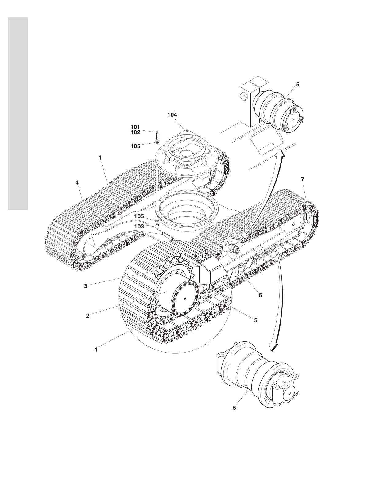
FIGURE 1-1. FRAME ASSEMBLY
FIG & ITEM # PART NUMBER DESCRIPTION QTY. REV.
FRAME OPTIONS: Ref.
Frame Weldment - with Steel Track Options:
2360529 600SC - Prior to S/N 0300064782
2360578 600SC - S/N 0300064782 to S/N 0300067081
2360582 600SC - S/N 0300067081 to S/N 0300128000
2360440 600SJC - Prior to S/N 0300064782
2360579 600SJC - S/N 0300064782 to S/N 0300067081
2360583 600SJC - S/N 0300067081 to S/N 0300128000
2360528 660SJC - Prior to S/N 0300064782
2360580 660SJC - S/N 0300064782 to S/N 0300067081
2360584 660SJC - S/N 0300067081 to S/N 0300128000
2360439 COMPLETE FRAME ASSEMBLY (STEEL TRACK) Ref.
1 7022708 Track Shoe Assembly (See Figure 1-2 for Breakdown) 2
2 Drive Assembly (See Figure 1-3 for Breakdown) 2
7022677 Prior to S/N 0300067081
NPN S/N 0300067081 to S/N 0300128000
3 See Note Sprocket Installation (See Figure 1-3 for Breakdown)
(Note: Not Available - Purchase Complete Assembly)
4 See Note Motor Guard Installation (See Figure 1-3 for Breakdown)
(Note: Not Available - Purchase Complete Assembly)
5 See Note Roller Assemblies Installation (See Figure 1-7 for
Breakdown)
(Note: Not Available - Purchase Complete Assembly)
6 See Note Track Guide Installation
(Note: Not Available - Purchase Complete Assembly)
7022675 Guide (1 Per Side) 2
7022644 Bolt M16 x 35mm (4 Per Side) 8
7022647 Washer 3.50mm (4 Per Side) 8
7 See Note Idler Assembly (See Figure 1-8 for Breakdown)
(Note: Not Available - Purchase Complete Assembly)
2
2
2
2
2
S
E
C
T
I
O
N
1
F
R
A
M
E
0257440 BEARING ADAPTER PLATE INSTALLATION Ref. B
101 0100019 Compound, Locking A/R
102 0682028 Bolt 5/8in-11NC x 3-1/2in (Grade 8) 30
103 3272001 Nut 5/8in-11NC 30
104 4845456 Adapter Weldment 1
105 4892000 Washer, Hardened 5/8in 60
3120795 1-3
Page 10
SECTION 1 FRAME
S
E
C
T
I
O
N
1
F
R
A
M
E
FIGURE 1-2. TRACK SHOE ASSEMBLY
1-4 3120795
Page 11

SECTION 1 FRAME
.
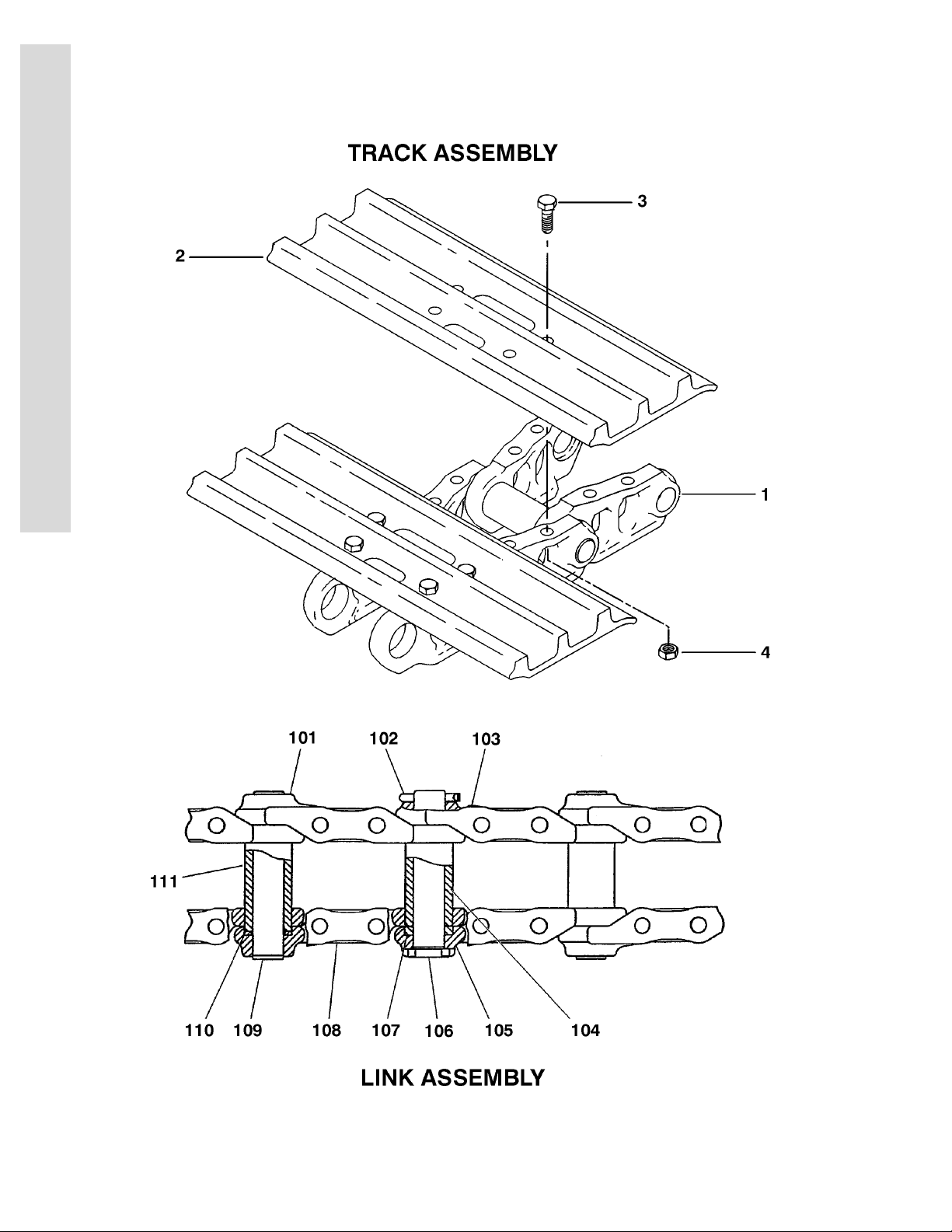
FIGURE 1-2. TRACK SHOE ASSEMBLY
FIG & ITEM # PART NUMBER DESCRIPTION QTY. REV.
7022708 TRACK SHOE ASSEMBLY - STEEL Ref.
1 7022680 Link Assembly (See Items 101-111 for Breakdown) 1
2 7022602 Shoe, Track Options: 43
3 7022612 Bolt M16 x 46mm 172
4 7022614 Nut M16 x 46mm 172
7022680 LINK ASSEMBLY Ref.
101 7022606 Link, Track 42
102 7022652 Pin, Cotter 1
103 7022608 Link, Track (Master) 1
104 7022651 Bushing 1
105 7022609 Link, Track (Master) 1
106 7022664 Pin (Master Link) 1
107 7022683 Spacer 2
108 7022607 Link, Track (Standard) 42
109 7022615 Pin (Standard Link) 42
110 7022616 Washer, Seal 172
111 7022679 Bushing 42
S
E
C
T
I
O
N
1
F
R
A
M
E
0270107 RUBBER PAD INSTALLATION (OPTIONAL - NOT SHOWN) Ref. A
Note: Used as a cover over steel track shoes only. Ref.
3340887 Pad, Rubber Cover 86
3120795 1-5
Page 12
SECTION 1 FRAME
S
E
C
T
I
O
N
1
F
R
A
M
E
FIGURE 1-3. DRIVE AND SPROCKET INSTALLATION
1-6 3120795
Page 13

SECTION 1 FRAME
.
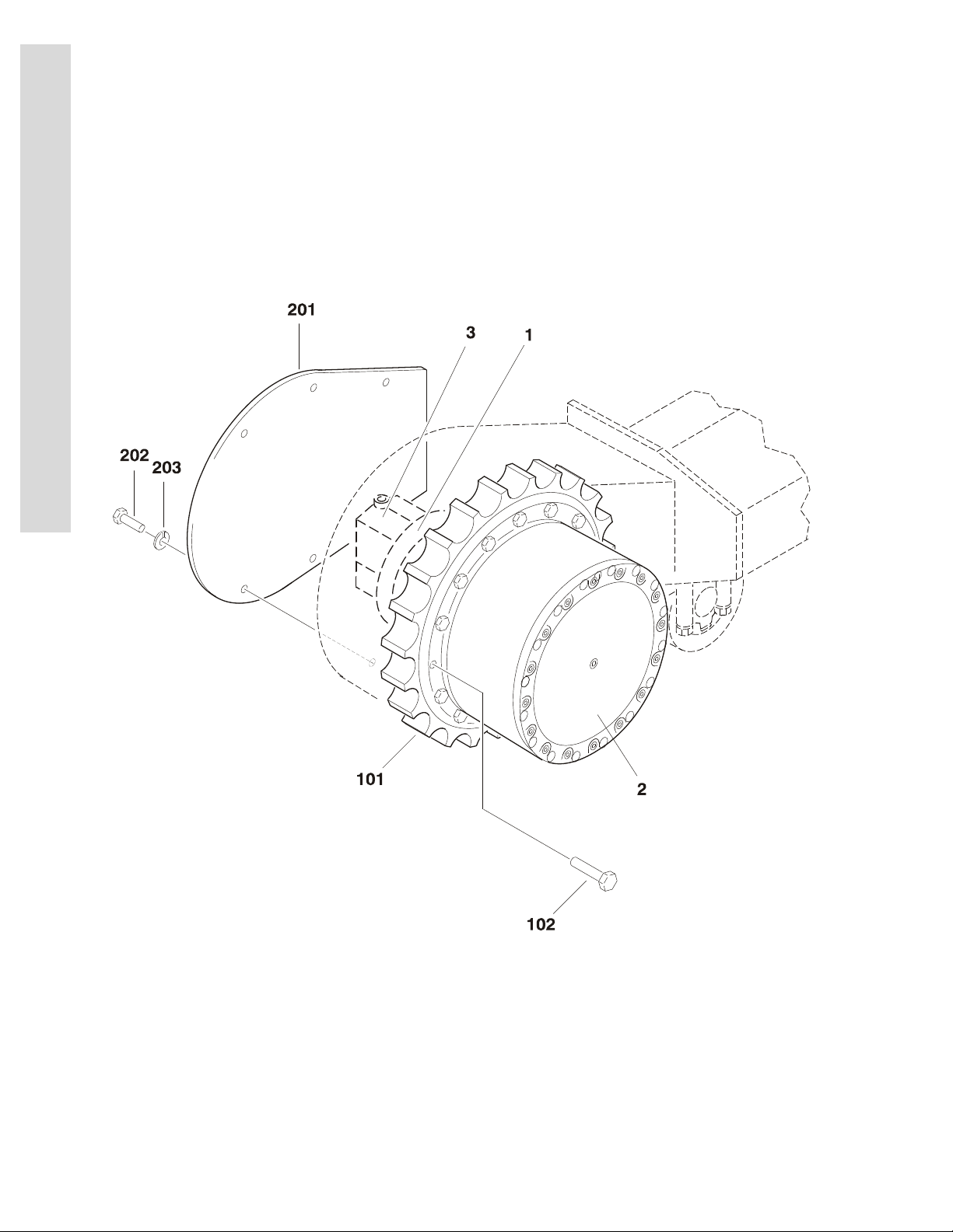
FIGURE 1-3. DRIVE AND SPROCKET INSTALLATION
FIG & ITEM # PART NUMBER DESCRIPTION QTY. REV.
DRIVE ASSEMBLY Ref.
7022677 Prior to S/N 0300067081 Ref.
NPN S/N 0300067081 to S/N 0300128000 Ref.
1 Drive Motor Assembly Options (See Figure 1-4 for
Breakdown):
7022718 Prior to S/N 0300067081
See Note S/N 0300067081 to S/N 0300128000
(Note: Not Available for Purchase.)
2 Drive Hub Assembly Options (See Figure 1-5 for Break-
down):
7022678 Prior to S/N 0300067081
7022737 S/N 0300067081 to S/N 0300128000
3 7022715 Drive Valve Assembly (See Figure 1-6 for Breakdown): 1
SPROCKET INSTALLATION Ref.
101 7022605 Sprocket 1
102 See Note Bolt M16 x 40mm (Note: Not Available for Purchase.) 15
1
1
S
E
C
T
I
O
N
1
F
R
A
M
E
COVER INSTALLATION Ref.
201 7022613 Plate, Cover 2
202 See Note Bolt M12 x 25mm (Note: Not Available for Purchase.) 12
203 7022617 Washer, Hardened 12
3120795 1-7
Page 14
SECTION 1 FRAME
S
E
C
T
I
O
N
1
F
R
A
M
E
FIGURE 1-4. DRIVE MOTOR ASSEMBLY
1-8 3120795
Page 15

SECTION 1 FRAME
.
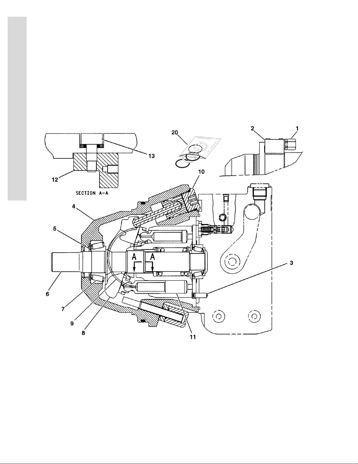
FIGURE 1-4. DRIVE MOTOR ASSEMBLY
FIG & ITEM # PART NUMBER DESCRIPTION QTY. REV.
7022718 DRIVE MOTOR ASSEMBLY (PRIOR TO S/N 0300067081) Ref.
1 7022674 Valve, Pilot 1
2 7022681 Block, Valve 1
See Note Bolt, Socket Head M6 x 40mm (Note: Not Available for
Purchase.)
See Note O-Ring (Note: Not Available for Purchase.) 3
3 7022673 Pin, Dowel 1
4 7022716 Housing, Motor 1
5 7022717 Ring, Retraining 1
6 7022712 Shaft 1
7 7022676 Bearing Set 1
See Note Shim Pack (Use if Required) (Note: Not Available for
Purchase.)
8 7022672 Swashplate 1
9 7022714 Shell, Cradle 1
10 7022682 Control, Motor 1
11 7022711 Rotating Assembly 1
12 7022666 Clamp, Retaining 2
13 7022667 Screw, Dowel 2
14 to 19 Not Used
20 7022713 Seal Kit 1
4
1
S
E
C
T
I
O
N
1
F
R
A
M
E
70003806 DRIVE MOTOR ASSEMBLY (S/N 0300067081 TO
S/N 0300128000)
Note: Must Purchase Complete Drive Motor Assembly. Ref.
Ref.
3120795 1-9
Page 16
SECTION 1 FRAME
S
E
C
T
I
O
N
1
F
R
A
M
E
FIGURE 1-5. DRIVE HUB ASSEMBLY
1-10 3120795
Page 17

SECTION 1 FRAME
.
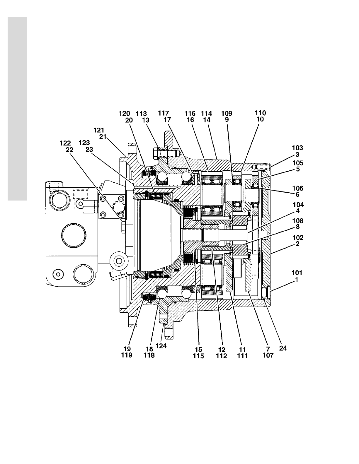
FIGURE 1-5. DRIVE HUB ASSEMBLY
FIG & ITEM # PART NUMBER DESCRIPTION QTY. REV.
7022678 DRIVE HUB ASSEMBLY (PRIOR TO S/N 0300067081) Ref.
1 7022692 Drain Plug Kit 2
2 7022693 Cover Assembly 1
3 7022694 Cover Fastener Kit 1
4 7022703 Shaft, Sun Gear 1
5 7022670 Planet Gear Kit 1
6 7022671 Disc, Support 3
7 7022704 Planet Carrier Kit 1
8 7022705 Sun Gear Kit 1
9 7022669 Disc, Support 3
10 7022668 Planet Gear Kit 1
11 7022706 Planet Carrier Kit 1
12 7022707 Sun Gear Kit 1
13 7022695 Gear Fastener Kit 1
14 7022696 Gear, Ring 1
15 7022697 Link, Shaft 1
16 7022698 Gear Kit 1
17 7022699 Shaft Nut Kit 1
18 7022700 Bearing Kit 1
19 7022701 Duo Cone Seal Kit 1
20 7022719 Brake Kit 1
21 7022702 Spindle 1
22 7022640 Bolt M12 x 25mm 2
23 7022646 O-Ring 1
24 7024972 O-Ring 1
S
E
C
T
I
O
N
1
F
R
A
M
E
7022737 DRIVE HUB ASSEMBLY (S/N 0300067081 TO
S/N 0300128000)
101 7022692 Drain Plug Kit 2
102 7022738 Cover Assembly 1
103 7022694 Cover Fastener Kit 1
104 7022739 Shaft, Sun Gear 1
105 7022740 Planet Gear Kit 1
106 7022671 Disc, Support 3
107 7022741 Planet Carrier Kit 1
108 7022742 Sun Gear Kit 1
109 7022671 Disc, Support 3
110 7022743 Planet Gear Kit 1
111 7022744 Planet Carrier Kit 1
112 7022745 Sun Gear Kit 1
113 7022695 Gear Fastener Kit 1
114 7022746 Gear, Ring 1
115 7022697 Link, Shaft 1
116 7022747 Gear Kit 1
117 70002816 Shaft Nut Kit 1
118 7022748 Bearing Kit 1
Ref.
3120795 1-11
Page 18

SECTION 1 FRAME
S
E
C
T
I
O
N
1
F
R
A
M
E
FIGURE 1-5. DRIVE HUB ASSEMBLY (CONTINUED)
FIG & ITEM # PART NUMBER DESCRIPTION QTY. REV.
119 70002817 Duo Cone Seal Kit 1
120 7022719 Brake Kit 1
121 7022749 Spindle 1
122 7022640 Bolt M12 x 25mm 2
123 7022646 O-Ring 1
124 7022750 Ring, Support 1
1-12 3120795
Page 19

SECTION 1 FRAME
FIGURE 1-5. DRIVE HUB ASSEMBLY (CONTINUED)
FIG & ITEM # PART NUMBER DESCRIPTION QTY. REV.
S
E
C
T
I
O
N
1
F
R
A
M
E
3120795 1-13
Page 20
SECTION 1 FRAME
S
E
C
T
I
O
N
1
F
R
A
M
E
FIGURE 1-6. DRIVE VALVE ASSEMBLY
1-14 3120795
Page 21

SECTION 1 FRAME
.
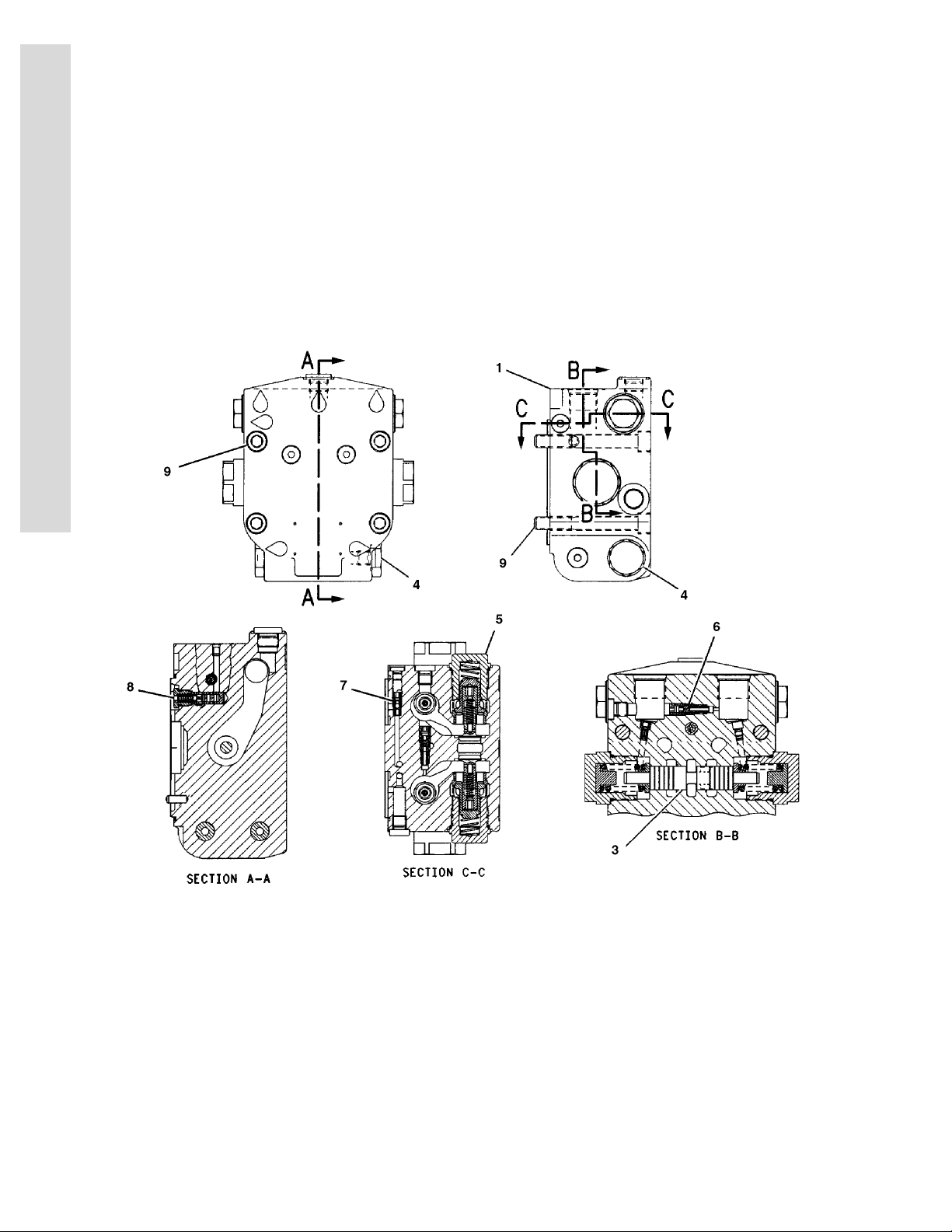
FIGURE 1-6. DRIVE VALVE ASSEMBLY
FIG & ITEM # PART NUMBER DESCRIPTION QTY. REV.
7022715 DRIVE VALVE ASSEMBLY Ref.
1 7022685 Port Plate Assembly 1
7022684 Seal Kit - 7022685 Port Plate 1
2 Not Used
3 7022686 Cartridge, Valve (Drive) 1
4 7022687 Cartridge, Valve (Relief) 2
5 7022688 Cartridge, Valve (Check) 2
6 7022689 Cartridge, Valve (Selector) 1
7 7022690 Cartridge, Valve (Adapter) 1
8 7022691 Cartridge, Valve (Brake) 1
9 7022628 Bolt M12 x 100mm 4
S
E
C
T
I
O
N
1
F
R
A
M
E
3120795 1-15
Page 22
SECTION 1 FRAME
S
E
C
T
I
O
N
1
F
R
A
M
E
FIGURE 1-7. ROLLER ASSEMBLIES INSTALLATION
1-16 3120795
Page 23

SECTION 1 FRAME
.
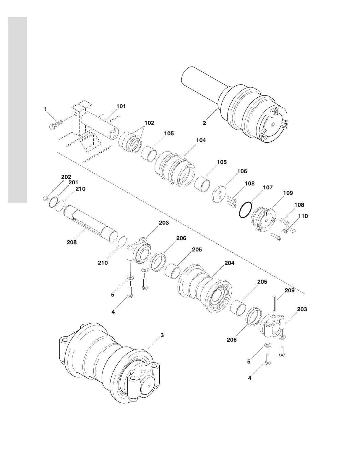
FIGURE 1-7. ROLLER ASSEMBLIES INSTALLATION
FIG & ITEM # PART NUMBER DESCRIPTION QTY. REV.
ROLLER ASSEMBLIES INSTALLATION Ref.
1 7022645 Bolt M24 x 80mm 4
2 7022604 Roller Assembly - Upper (See Items 101-110 for Breakdown) 4
3 7022709 Roller Assembly - Lower (See Items 201-210 for Breakdown) 14
4 7022629 Bolt M16 x 80mm 56
5 7022638 Washer 56
7022604 ROLLER ASSEMBLY - UPPER Ref.
101 7022632 Shaft 1
102 7022662 Seal Kit 1
103 Not Used
104 7022630 Roller & Bearing Assembly 1
105 See Note Bearing (Note: Not Available for Purchase.) 2
106 7022633 Retainer 1
107 7022625 O-Ring 1
108 7022637 Bolt, Socket Head M10 x 25mm 5
109 7022631 Cover, Carrier Roller 1
110 7022627 Plug, Pipe 1
S
E
C
T
I
O
N
1
F
R
A
M
E
7022709 ROLLER ASSEMBLY - LOWER Ref.
201 7022619 Retainer 1
202 7022627 Plug, Pipe 1
203 7022611 Collar 2
204 7022618 Roller & Bearing Assembly 1
205 See Note Bearing (Note: Not Available for Purchase.) 2
206 7022663 Seal Kit 2
207 Not Used
208 See Note Shaft (Note: Not Available for Purchase.) 1
209 7022623 Dowel 1
210 7022626 O-Ring 2
3120795 1-17
Page 24
SECTION 1 FRAME
S
E
C
T
I
O
N
1
F
R
A
M
E
FIGURE 1-8. IDLER ASSEMBLY
1-18 3120795
Page 25

SECTION 1 FRAME
.
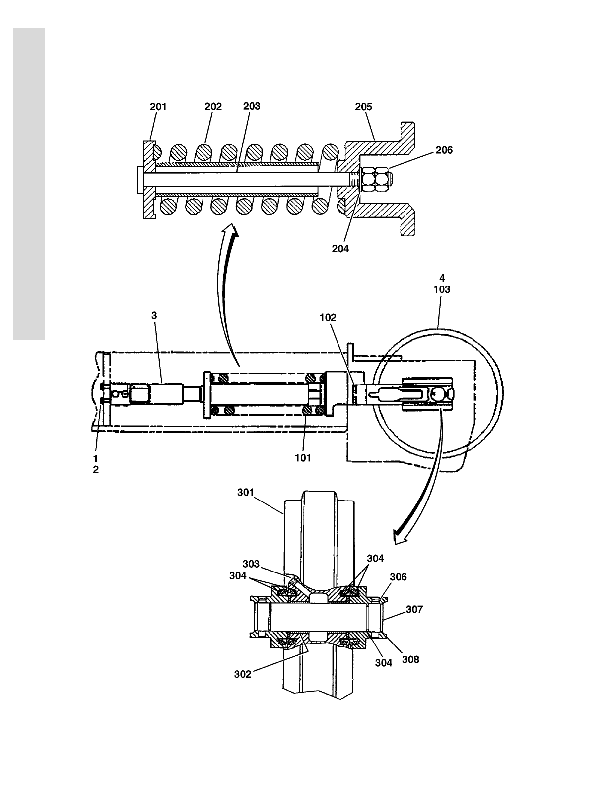
FIGURE 1-8. IDLER ASSEMBLY
FIG & ITEM # PART NUMBER DESCRIPTION QTY. REV.
IDLER ASSEMBLY Ref.
1 7022639 Bolt M21 x 40mm 4
2 See Note Washer, Hardened (Note: Not Available - Purchase
Locally.)
3 See Note Track Adjuster Assembly (See Figure 1-9 for Breakdown)
(Note: Not Available - Purchase Complete Assembly)
4 See Note Idler Assembly (See Items 101-103 for Breakdown)
(Note: Not Available - Purchase Complete Assembly)
IDLER ASSEMBLY Ref.
101 See Note Recoil Spring Assembly (See Items 201-206 for Breakdown)
(Note: Not Available - Purchase Complete Assembly)
102 7022639 Bolt M16 x 50mm 4
103 See Note Idler Wheel Assembly (See Items 301-308 for Breakdown)
(Note: Not Available - Purchase Complete Assembly)
RECOIL SPRING ASSEMBLY Ref.
4
2
2
1
1
S
E
C
T
I
O
N
1
F
R
A
M
E
201 7022649 Support 1
202 7022659 Spring 1
203 7022621 Rod 1
204 7022648 Washer 1
205 7022620 Support 1
206 7022635 Nut M30 2
IDLER WHEEL ASSEMBLY Ref.
301 7022624 Idler Wheel & Bearing Assembly 1
302 See Note Bearing (Note: Not Available for Purchase.) 2
303 7022627 Plug, Pipe 1
304 7022657 Seal Kit (1 Kit Includes 2 Seals & 1 O-Ring) 2
305 Not Used
306 7022658 Pin 2
307 7022622 Shaft, Idler Wheel 1
308 7022610 Bearing 2
3120795 1-19
Page 26
SECTION 1 FRAME
S
E
C
T
I
O
N
1
F
R
A
M
E
FIGURE 1-9. TRACK ADJUSTER ASSEMBLY
1-20 3120795
Page 27

SECTION 1 FRAME
.
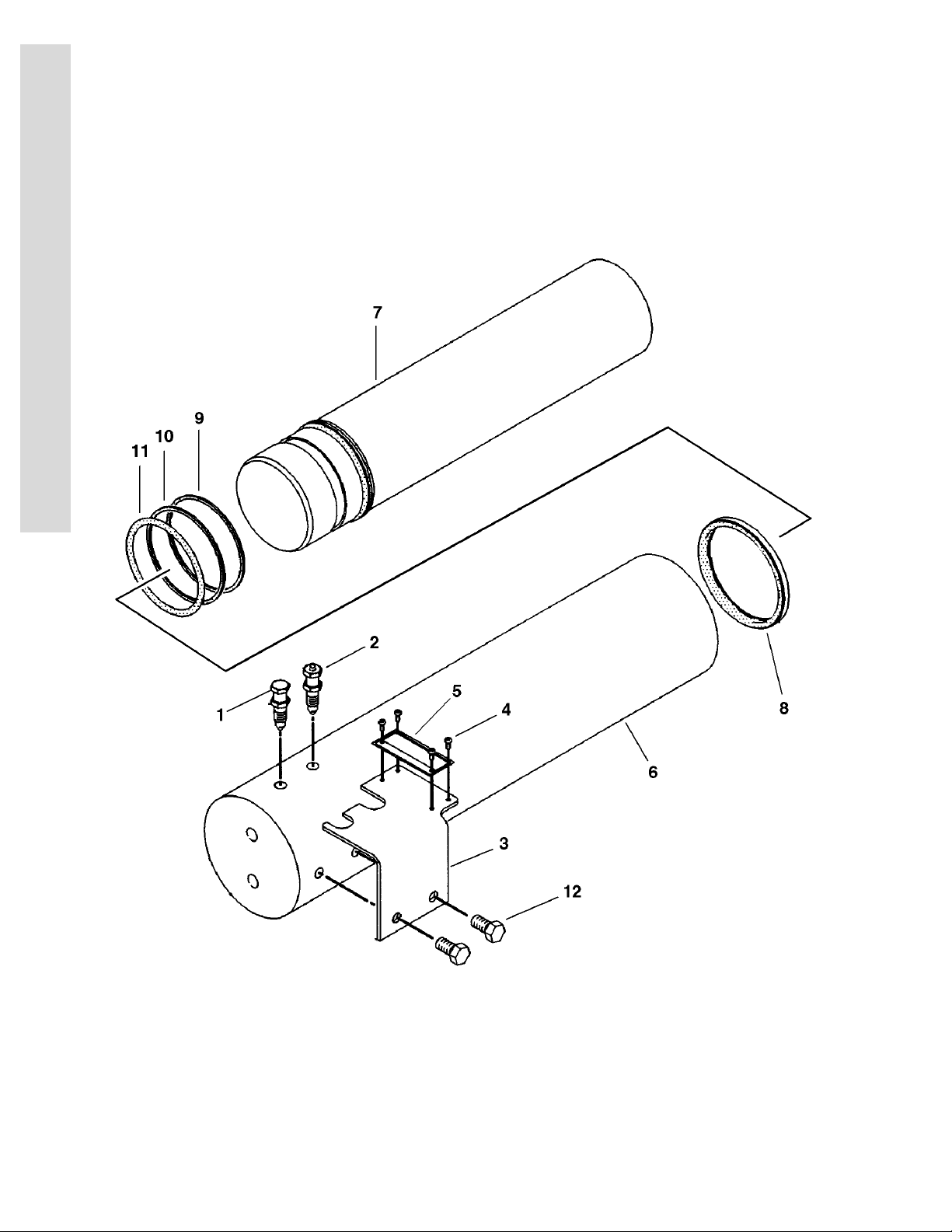
FIGURE 1-9. TRACK ADJUSTER ASSEMBLY
FIG & ITEM # PART NUMBER DESCRIPTION QTY. REV.
TRACK ADJUSTER ASSEMBLY Ref.
1 7022601 Cartridge, Valve (Relief) 1
2 7022655 Cartridge, Valve (Fill) 1
3 7022665 Plate Assembly 1
4 See Note Screw, Drive (Note: Not Available for Purchase.) 4
5 See Note Plate, Warning (Note: Not Available for Purchase.) 1
6 7022600 Barrel, Cylinder 1
7 7022650 Piston 1
8 7022656 Seal, Lip 1
9 7022660 Ring, Back-up 2
10 7022661 Ring, Back-up 2
11 7022653 O-Ring 2
12 7022642 Bolt M8 x 12mm 2
S
E
C
T
I
O
N
1
F
R
A
M
E
3120795 1-21
Page 28

SECTION 1 FRAME
S
E
C
T
I
O
N
1
F
R
A
M
E
FIGURE 1-9. TRACK ADJUSTER ASSEMBLY (CONTINUED)
FIG & ITEM # PART NUMBER DESCRIPTION QTY. REV.
1-22 3120795
Page 29

SECTION 2 3 TURNTABLE
TABLE OF CONTENTS
FIGURE DESCRIPTION PAGE
2-1 CONTROL VALVES INSTALLATIONS . . . . . . . . . . . . . . . . . . . . . . . . . . . . . . . . . . . . . . . . . . . . 2-2
2-2 MAIN CONTROL VALVE ASSEMBLY. . . . . . . . . . . . . . . . . . . . . . . . . . . . . . . . . . . . . . . . . . . . . 2-6
2-3 ARTICULATING JIB VALVE ASSEMBLY . . . . . . . . . . . . . . . . . . . . . . . . . . . . . . . . . . . . . . . . . . 2-10
2-4 SWING DRIVE, TURNTABLE BEARING & LOCK INSTALLATIONS . . . . . . . . . . . . . . . . . . . . 2-12
2-5 SWING HUB ASSEMBLY . . . . . . . . . . . . . . . . . . . . . . . . . . . . . . . . . . . . . . . . . . . . . . . . . . . . . 2-16
2-6 SWING BRAKE ASSEMBLY . . . . . . . . . . . . . . . . . . . . . . . . . . . . . . . . . . . . . . . . . . . . . . . . . . . 2-18
2-7 SWING MOTOR ASSEMBLY (WHITE ROLLER STATOR) . . . . . . . . . . . . . . . . . . . . . . . . . . . . . 2-22
2-8 SWING MOTOR ASSEMBLY (PARKER) . . . . . . . . . . . . . . . . . . . . . . . . . . . . . . . . . . . . . . . . . . 2-24
2-9 DEUTZ ENGINE INSTALLATION . . . . . . . . . . . . . . . . . . . . . . . . . . . . . . . . . . . . . . . . . . . . . . . . 2-26
2-10 GENERATOR INSTALLATION - DEUTZ MACHINES (OPTIONAL) . . . . . . . . . . . . . . . . . . . . . 2-32
2-11 PISTON PUMP ASSEMBLY . . . . . . . . . . . . . . . . . . . . . . . . . . . . . . . . . . . . . . . . . . . . . . . . . . . . 2-36
2-12 GEAR PUMP ASSEMBLY. . . . . . . . . . . . . . . . . . . . . . . . . . . . . . . . . . . . . . . . . . . . . . . . . . . . . . 2-42
2-13 TANK INSTALLATIONS. . . . . . . . . . . . . . . . . . . . . . . . . . . . . . . . . . . . . . . . . . . . . . . . . . . . . . . . 2-44
2-14 ROTARY COUPLING INSTALLATION . . . . . . . . . . . . . . . . . . . . . . . . . . . . . . . . . . . . . . . . . . . . 2-46
2-15 GROUND CONTROL BOX ASSEMBLY . . . . . . . . . . . . . . . . . . . . . . . . . . . . . . . . . . . . . . . . . . . 2-48
2-16 ELECTRICAL OPTIONS INSTALLATION (TURNTABLE MOUNTED) . . . . . . . . . . . . . . . . . . . . 2-52
2-17 ENGINE TRAY JACK INSTALLATION (OPTIONAL). . . . . . . . . . . . . . . . . . . . . . . . . . . . . . . . . . 2-56
2-18 HOODS & LIFTING PLATE INSTALLATIONS . . . . . . . . . . . . . . . . . . . . . . . . . . . . . . . . . . . . . . 2-58
S
E
C
T
I
O
N
2
T
U
R
N
T
A
B
L
E
3120795 2-1
Page 30
S
E
C
T
I
O
N
2
T
U
R
SECTION 2 3 TURNTABLE
FIGURE 2-1. CONTROL VALVES INSTALLATIONS
N
T
A
B
L
E
2-2 3120795
Page 31

SECTION 2 3 TURNTABLE
.
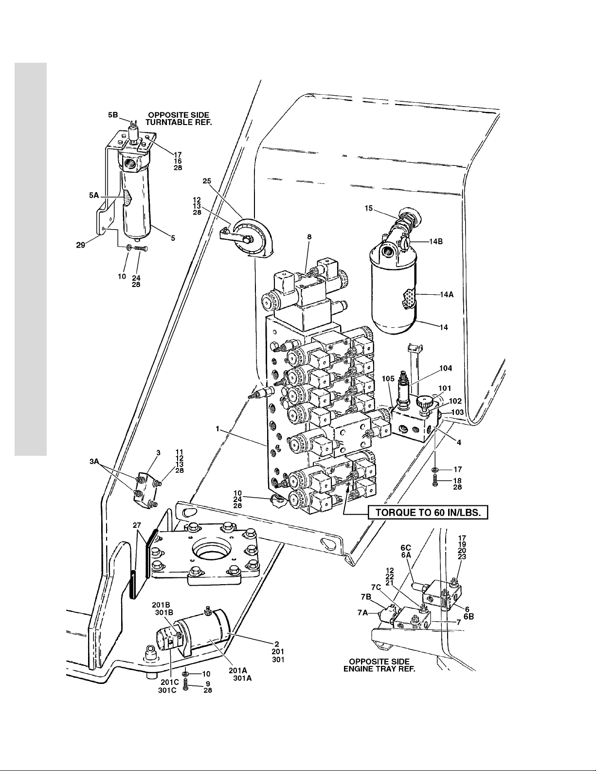
FIGURE 2-1. CONTROL VALVES INSTALLATIONS
FIG & ITEM # PART NUMBER DESCRIPTION QTY. REV.
VALVES INSTALLATIONS Ref.
0257488 600SC (Prior to S/N 0300064782) Ref. 5
0271631 600SC (S/N 0300064782 to S/N 0300128000) Ref. 3
0257489 600SJC & 660SJC (Prior to S/N 0300064782) Ref. 5
0271667 600SJC & 660SJC (S/N 0300064782 to S/N 0300128000) Ref. 3
1 4641017 Main Control Valve Assembly (See Figure 2-2 for
Breakdown)
2 Auxiliary Pump Assemblies Options: 1
3600243 Auxiliary Pump Assembly (See Item 201 for Breakdown)
(Prior to S/N 0300070773)
3600365 Auxiliary Pump Assembly (See Item 301 for Breakdown)
(S/N 0300070773 to S/N 0300128000)
3 4640908 Counterbalance Valve Assembly 1
3A 7011328 Cartridge, Counterbalance 2
2900770 Seal, Kit - 7011328 Cartridge 2
4 4640931 Manual Descent Valve Assembly (See Items 101-105 for
Breakdown) (Prior to S/N 0300071456)
5 2120146 Hydraulic Pressure Filter Assembly 1
5A 2120150 Element, Filter 1
5B 7016312 Indicator, Clogged 1
6 4640689 Valve Assembly (Pressure Reducing)
(Prior to S/N 0300061570 Only)
6A 7010530 Cartridge 1
7010531 Seal Kit - 7010530 Cartridge 1
6B 4640907 Valve Assembly (Pressure Reducing)
(S/N 0300064782 to S/N 0300128000)
6C 7012941 Cartridge 1
7010543 Seal Kit - 7012941 Cartridge 1
7 4640906 Valve Assembly (Two Speed) 1
7A 7023981 Cartridge without Coil 1
7012905 Seal Kit - 7023981 Cartridge 1
7B 7012944 Coil 1
7C 7017481 Cartridge, Check 2
7012972 Seal Kit 2
8 Valve Kit (Articulating Jib) Options: A/R
Not Required 600SC 0
4640921 600SJC & 660SJC (See Figure 2-3 for Breakdown) 1
9 0641613 Bolt 3/8in-16NC x 1-5/8in 2
10 4711600 Flatwasher 3/8in Thin 7
11 4891800 Flatwasher 1/2in Hardened 2
12 4751500 Flatwasher 5/16in Regular 5
13 3311501 Nut 5/16in-18NC 3
14 2120145 Return Filter Assembly 1
14A 2120149 Element, Filter 1
14B 7016313 Indicator, Clogged 1
15 2220893 Fitting, Adapter 1
16 0651406 Bolt 1/4in-28NF x 3/4in 4
17 4711400 Flatwasher 1/4in Thin A/R
1
1
1
1
S
E
C
T
I
O
N
2
T
U
R
N
T
A
B
L
E
3120795 2-3
Page 32

SECTION 2 3 TURNTABLE
FIGURE 2-1. CONTROL VALVES INSTALLATIONS (CONTINUED)
S
E
C
T
I
O
N
2
T
U
R
N
T
A
B
L
E
FIG & ITEM # PART NUMBER DESCRIPTION QTY. REV.
18 0651406 Bolt 1/4in-28NF x 3/4in (Prior to S/N 0300071456) 3
19 Bolt Options: 2
0641420 Bolt 1/4in-20NC x 2-1/2in (Prior to S/N 0300061570 Only)
0641416 Bolt 1/4in-20NC x 2in (S/N 0300064782 to
S/N 0300128000)
20 4891400 Flatwasher 1/4in Hardened Options: A/R
Prior to S/N 0300061570 Only 2
S/N 0300064782 to S/N 0300128000 4
21 0641508 Bolt 5/16in-18NC x 1in 2
22 4891500 Flatwasher 5/16in Hardened 2
23 3311405 Locknut 1/4in-20NC 2
24 0641608 Bolt 3/8in-16NC x 1in 5
25 0140001 Horn 1
26 Not Used
27 4060918 Flex-Trim
28 0100011 Compound, Locking A/R
29 0902587 Bracket, Filter 1
4640931 MANUAL DESCENT VALVE ASSEMBLY (Prior to
S/N 0300071456)
101 7012961 Knob 1
102 7012954 Cartridge, Needle Valve 1
7012953 Seal Kit - 7012954 Valve 1
103 7012975 Cartridge, Check Valve 1
7012540 Seal Kit - 7012975 Valve 1
104 7012976 Cartridge, Relief Valve 1
7012953 Seal Kit - 7012976 Valve 1
105 7012977 Cartridge, Pilot Valve 1
7012918 Seal Kit - 7012977 Valve 1
40in/10m
Ref.
3600243 AUXILIARY PUMP ASSEMBLY (Prior to S/N 0300070773) Ref. B
201 3600243 Auxiliary Pump Assembly 1
201A 7013755 Replacement Motor 1
7013799 Brush Kit - 7013755 1
7016744 Bolt (Mounts Motor to Mounting Bracket) 2
201B 7013711 Coupling 1
201C 7013796 Replacement Pump 1
See Note Seal Kit (Note: Not Available - Purchase Individual
Pieces.)
7016700 Seal, Oil 1
7016701 O-Ring 1
7016702 O-Ring 1
7022203 Bolt (Mounts Pump to Mounting Bracket) 2
2-4 3120795
1
Page 33

SECTION 2 3 TURNTABLE
FIGURE 2-1. CONTROL VALVES INSTALLATIONS (CONTINUED)
FIG & ITEM # PART NUMBER DESCRIPTION QTY. REV.
3600365 AUXILIARY PUMP ASSEMBLY (S/N 0300070773 to
S/N 03000128000)
301 3600365 Auxiliary Pump Assembly 1
301A Replacement Motor Options: 1
Use 7004290 Replacement Motor with Endhead Item 105
(was p/n 7011067)
7004248 Replacement Motor without Endhead
7011065 Brush Kit - Motor 1
See Note Bolt (Mounts Motor to Endhead) (Note: Not Available
for
Purchase.)
7011062 Endhead 4
301B 7011063 Coupling & Hardware Kit (Includes Pump Gasket &
Hardware)
301C 7011064 Replacement Pump 1
7011044 Gasket 1
7011066 Seal Kit 1
See Note Relief Valve (Note: Not Available - Purchase Complete
Pump.)
7011043 Bolt (Mounts Pump to Mounting Bracket) 4
7011048 Lockwasher 4
Ref. B
4
1
1
S
E
C
T
I
O
N
2
T
U
R
N
T
A
B
L
E
3120795 2-5
Page 34

S
E
C
T
I
O
N
2
T
U
R
SECTION 2 3 TURNTABLE
FIGURE 2-2. MAIN CONTROL VALVE ASSEMBLY
N
T
A
B
L
E
2-6 3120795
Page 35

SECTION 2 3 TURNTABLE
.
FIGURE 2-2. MAIN CONTROL VALVE ASSEMBLY
FIG & ITEM # PART NUMBER DESCRIPTION QTY. REV.
4641017 MAIN CONTROL VALVE ASSEMBLY Ref. B
1 7017410 Cartridge, Without Coil 1
7012967 Seal Kit - 7017410 Cartridge 1
1A 7012944 Coil 1
2 7017411 Cartridge, Pressure Sensing 1
7012518 Seal Kit 1
3 7012912 Cartridge (Main Relief) 1
7012998 Seal Kit 1
4 7021373 Control Valve Assembly (Platform Level) 1
7012773 Seal Kit 1
7012799 Lanyard Assembly 1
4A 7021376 Coil 2
5 7012914 Cartridge, Check Valve (Platform Level) 1
7012918 Seal Kit - 7012914 Cartridge 1
6 7012914 Cartridge, Check Valve (Platform Level) 1
7012918 Seal Kit - 7012914 Cartridge 1
7 7012912 Cartridge, Relief Valve (Platform Level) 1
7012998 Seal Kit - 7012912 Cartridge 1
8 7012912 Cartridge, Relief Valve 1
7012998 Seal Kit - 7012912 Cartridge 1
9 7012989 Cartridge, Flow Control 1
7012953 Seal Kit - 7012989 Cartridge 1
10 7021373 Control Valve Assembly (Platform Rotate) 1
7012773 Seal Kit 1
7012799 Lanyard Assembly 1
10A 7021376 Coil 2
11 Use 70000579 Control Valve Assembly (Upper Tele) (was p/n 7012766) 1
Note: Refer to Vendor P/N on Valve Nameplate before
ordering Parts. P/N 7012766 is RR00567495 or
R900567495. P/N 70000579 is R900930080.
Seal Kit Options: 1
7012769 7012766 Valve
70000583 70000579 Valve
11A Coil Options: 1
7012772 7012766 Valve (was p/n 7012768)
70000582 70000579 Valve
Nut, Coil Options: 1
7018912 7012766 Valve
70000580 70000579 Valve
12 7022521 Control Valve Assembly (Flow Control) 1
7012773 Seal Kit 1
12A 7018991 Coil 1
13 7010542 Cartridge, Shuttle 1
7010543 Seal Kit - 7010542 Cartridge 1
14 Not Used
15 7010542 Cartridge, Shuttle 1
7010543 Seal Kit - 7010542 Cartridge 1
Ref.
S
E
C
T
I
O
N
2
T
U
R
N
T
A
B
L
E
3120795 2-7
Page 36

SECTION 2 3 TURNTABLE
FIGURE 2-2. MAIN CONTROL VALVE ASSEMBLY (CONTINUED)
S
E
C
T
I
O
N
2
T
U
R
N
T
A
FIG & ITEM # PART NUMBER DESCRIPTION QTY. REV.
16 7010542 Cartridge, Shuttle 1
7010543 Seal Kit - 7010542 Cartridge 1
17 7010542 Cartridge, Shuttle 1
7010543 Seal Kit - 7010542 Cartridge 1
18 7012912 Cartridge, Relief Valve 1
7012998 Seal Kit - 7012912 Cartridge 1
19 7012775 Control Valve Assembly (Upper Lift) 1
7012773 Seal Kit 1
19A 7012772 Coil 2
20 7012775 Control Valve Assembly (Swing) 1
7012773 Seal Kit 1
20A 7012772 Coil 2
21 7012912 Cartridge, Relief Valve 1
7012998 Seal Kit - 7012912 Cartridge 1
22 to 24 Not Used
25 See Note Orifice 1.2mm (Note: Not Available for Purchase.) 2
26 7021310 Block, Valve 1
B
L
E
2-8 3120795
Page 37

SECTION 2 3 TURNTABLE
FIGURE 2-2. MAIN CONTROL VALVE ASSEMBLY (CONTINUED)
FIG & ITEM # PART NUMBER DESCRIPTION QTY. REV.
S
E
C
T
I
O
N
2
T
U
R
N
T
A
B
L
E
3120795 2-9
Page 38

S
E
C
T
I
O
N
2
T
U
R
SECTION 2 3 TURNTABLE
FIGURE 2-3. ARTICULATING JIB VALVE ASSEMBLY
N
T
A
B
L
E
2-10 3120795
Page 39

SECTION 2 3 TURNTABLE
.
FIGURE 2-3. ARTICULATING JIB VALVE ASSEMBLY
FIG & ITEM # PART NUMBER DESCRIPTION QTY. REV.
4640921 ARTICULATING JIB VALVE ASSEMBLY Ref. D
1 7012965 Cartridge, Flow Control 1
7012953 Seal Kit - 7012965 Cartridge 1
2 Use 70001976 Directional Control Valve Assembly (was p/n 7012770) 1
7012773 Seal Kit 1
2A 7018945 O-Ring 2
2B 7018912 Nut 2
2C 7012772 Coil 2
3 7017421 Cartridge, Relief 1
7012998 Seal Kit - 7017421 Cartridge 1
4 7017422 Cartridge, Relief 1
7012998 Seal Kit - 7017422 Cartridge 1
5 4460499 Connector, DIN with Diode (Part of Valve Harness) 2
6 7012777 Capscrew, Socket Head 5/16in-11NC x 2-1/4in (Used to
Mount Valve Assembly)
7 7018942 Capscrew, Socket Head #10-24NC x 2in 4
8 7012776 O-Ring (Used to Mount to Main Valve) 2
4
S
E
C
T
I
O
N
2
T
U
R
N
T
A
B
L
E
3120795 2-11
Page 40

S
E
C
T
I
O
N
2
T
U
R
SECTION 2 3 TURNTABLE
FIGURE 2-4. SWING DRIVE, TURNTABLE BEARING & LOCK INSTALLATIONS
N
T
A
B
L
E
2-12 3120795
Page 41

SECTION 2 3 TURNTABLE
.
FIGURE 2-4. SWING DRIVE, TURNTABLE BEARING & LOCK INSTALLATIONS
FIG & ITEM # PART NUMBER DESCRIPTION QTY. REV.
4620127 TURNTABLE WELDMENT Ref. 1
SWING DRIVE INSTALLATION OPTIONS Ref.
0255025 Prior to S/N 0300064566 Ref. 3/B
0270329 S/N 0300064566 to S/N 0300128000 Ref. A
1 3537318 Plate, Swing Drive Mounting 1
2 0642018 Bolt 5/8in -11NC x 2-1/4in 10
3 4892000 Flatwasher 5/16in Hardened 10
4 0100011 Compound, Locking A/R
5 2780205 Swing Hub Assembly (See Figure 2-5 for Breakdown) 1
6 3932224 Bolt 1/2in-13NC x 1-1/2in 4
7 Swing Brake Assembly Options (See Figure 2-6 for
Breakdown):
Use 0920109 Prior to S/N 0300033476 (was p/n 0920083)
0920109 S/N 0300033476 to S/N 0300064566
0920119 S/N 0300064566 to S/N 0300128000
8 Bolt Options: 2
3931860 Prior to S/N 0300064566
Not Required S/N 0300064566 to S/N 0300128000
9 Swing Motor Assembly Options: 1
3160200 White Roller Stator Motor used Prior to S/N 0300064566
(See Figure 2-7 for Breakdown)
Use
1001110169
1001110169 Parker Motor use as Service Replacement (See Figure
10 Bolt Options: 2
0641810 Bolt 1/2in-13NC x 2-1/2in (Prior to S/N 0300064566)
0681836 Bolt 1/2in-13NC x 4-1/2in (Grade 8) (S/N 0300064566 to
11 4891800 Flatwasher 1/2in Hardened 2
White Roller Stator Motor used S/N 0300064566 to
S/N 0300128000 (was p/n 3160273 - See Figure 2-7 for
Breakdown)
2-8 for Breakdown)
S/N 0300128000)
1
S
E
C
T
I
O
N
2
T
U
R
N
T
A
B
L
E
0259055 TURNTABLE BEARING INSTALLATION Ref. B
101 Use 2915089 Bearing Kit (was p/n 0440233) (Kit Includes Bearing & Mount-
ing Hardware)
102 0682023 Bolt 5/8in - 11NC X 2-7/8in (Grade 8) 36
103 4892000 Flatwasher, Hardened 36
104 0100019 Compound, Locking A/R
0239585 TURNTABLE LOCK INSTALLATION Ref. B
201 3421627 Pin 1
202 3421565 Pin, Snap 1
203 3760170 Ring, Quick Release 2
204 1260017 Chain
3120795 2-13
1
9in/23cm
Page 42

SECTION 2 3 TURNTABLE
FIGURE 2-4. SWING DRIVE, TURNTABLE BEARING & LOCK INSTALLATIONS (CONTINUED)
S
E
C
T
I
O
N
2
T
U
R
N
T
A
FIG & ITEM # PART NUMBER DESCRIPTION QTY. REV.
0255316 REMOTE BEARING LUBE INSTALLATION Ref. 3
301 2751095 Hose, Grease (Prior to S/N 0300070975) 1
302 2180344 Fitting, Bulkhead A/R
303 2160003 Fitting, Grease 45° A/R
304 2220063 Fitting, 90° A/R
305 2751032 Hose, Grease 1
B
L
E
2-14 3120795
Page 43

SECTION 2 3 TURNTABLE
FIGURE 2-4. SWING DRIVE, TURNTABLE BEARING & LOCK INSTALLATIONS (CONTINUED)
FIG & ITEM # PART NUMBER DESCRIPTION QTY. REV.
S
E
C
T
I
O
N
2
T
U
R
N
T
A
B
L
E
3120795 2-15
Page 44
S
9865734
214010111224
23
25
26
26
21
13
171418
19
21A
20
22
29
27
28
141516
15
E
C
T
I
SECTION 2 3 TURNTABLE
FIGURE 2-5. SWING HUB ASSEMBLY
O
N
2
T
U
R
N
T
A
B
L
E
2-16 3120795
Page 45

SECTION 2 3 TURNTABLE
.
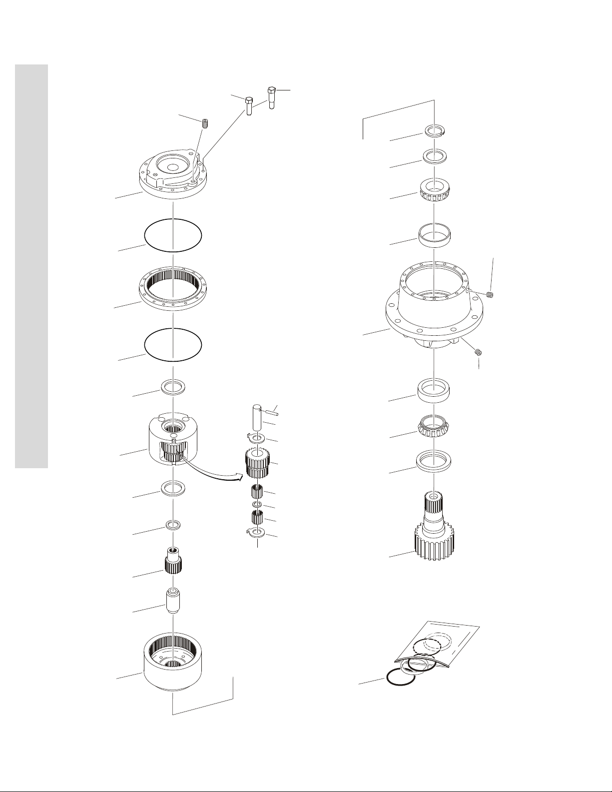
FIGURE 2-5. SWING HUB ASSEMBLY
FIG & ITEM # PART NUMBER DESCRIPTION QTY. REV.
2780205 SWING HUB ASSEMBLY Ref. —
HOUSING ASSEMBLY Ref.
1 7010492 Shaft, Output 1
2 7000228 Seal, Lip 1
3 7000255 Cup, Bearing 1
4 7000256 Cone, Bearing 1
5 7000257 Cup, Bearing 1
6 7000258 Cone, Bearing 1
7 7010496 Housing 1
8 7007633 Thrustwasher 1
9 7000229 Ring, Retaining 1
10 7010494 Pipe, Plug 2
11 7001928 Pipe, Plug 2
12 7000246 Gear, In O-Ring 2
— — — — — — — — — —
CARRIER ASSEMBLY Ref.
13 7001931 Carrier 1
14 7001985 Thrustwasher, Tanged 6
15 7001909 Bearing, Needle 96
16 7000263 Spacer, Thrust 3
17 7001911 Shaft, Planet 3
18 7001987 Gear, Cluster 3
19 7010474 Rollpin 3
20 7001988 Ring Gear 1
21 7000230 O-Ring (Black) 1
21A 7017070 O-Ring (White) 1
22 7000209 Cover, Input 1
23 7010488 Gear, Sun 1
24 7000269 Spacer, Input 1
25 7000270 Thrustwasher 1
26 7000253 Thrustwasher 2
27 7000217 Bolt 8
28 7000214 Bolt, Shoulder 4
29 2200222 Pipe, Plug 1
30 to 39 Not Used
S
E
C
T
I
O
N
2
T
U
R
N
T
A
B
L
E
40 7024100 Kit, Seal (Includes Items 2, 9, 21, 21A & 26) 1
3120795 2-17
Page 46
S
E
C
T
I
O
N
2
T
U
R
SECTION 2 3 TURNTABLE
FIGURE 2-6. SWING BRAKE ASSEMBLY
N
T
A
B
L
E
2-18 3120795
Page 47

SECTION 2 3 TURNTABLE
.
FIGURE 2-6. SWING BRAKE ASSEMBLY
FIG & ITEM # PART NUMBER DESCRIPTION QTY. REV.
SWING BRAKE ASSEMBLY OPTIONS: Ref.
0920083 Prior to S/N 0300033476 Ref. A
0920109 S/N 0300033476 to S/N 0300064566 Ref. B
1 7011720 Shaft 1
2 Guide, Spring Options: 1
7011717 0920083 Brake (Prior to S/N 0300033476)
7018606 0920109 Brake (S/N 0300033476 to S/N 0300064566)
3 Spring Options: A/R
7007979 0920083 Brake (Inner) (Prior to S/N 0300033476) 6
7007980 0920083 Brake (Outer) (Prior to S/N 0300033476) 6
7007970 0920109 Brake (Red) (S/N 0300033476 to
S/N 0300064566)
7018602 0920109 Brake (Blue) (S/N 0300033476 to
S/N 0300064566)
4 Housing Options: 1
7011713 0920083 Brake (Prior to S/N 0300033476)
7018605 0920109 Brake (S/N 0300033476 to S/N 0300064566)
5 Return Plate & Separator Assembly Options: A/R
Use 2900767 Plate, Return - 0920083 Brake (Prior to
S/N 0300033476)
7011715 Separator Assy - 0920083 Brake (Prior to
S/N 0300033476)
7011714 Pin 4
7007983 Separator 2
Use 7018608 Plate, Return/Separator - 0920109 Brake (S/N 0300033476
to S/N 0300064566)
6 See Note Rotor (Note: Use Item 200A, 201A, 202A, 202B or 203B) 2
7 See Note Stator (Note: Use Item 200A, 201A, 202A, 202B or 203B) 2
8 See Note Seal, Oil (Note: Use Item 200A, 201A, 202A, 202B or
203B)
9 Bolt, Washer Head Options: 4
7007985 0920083 Brake (Prior to S/N 0300033476)
7018607 0920109 Brake (S/N 0300033476 to S/N 0300064566)
10 7011719 Cover 1
11 Hardware Options: 1
7007914 Screw, Bleeder (Prior to S/N 0300033906)
7018609 Plug, Pipe (S/N 0300033906 to S/N 0300064566)
12 7007987 Pin, Dowel 2
13 See Note Seal, Oil (Note: Use Item 200A, 201A or 203B) 1
14 7011716 Ring, Retaining 1
15 See Note Bearing (Note: Use Item 201A or 203B) 1
16 7007977 Ring, Retaining 1
17 See Note Ring, Back-Up (Note: Use Item 200A or 203B) 1
18 See Note Ring, Back-Up (Note: Use Item 200A or 203B) 1
19 See Note O-Ring (Note: Use Item 200A or 203B) 1
20 See Note O-Ring (Note: Use Item 200A or 203B) 1
6
3
1
2
1
1
S
E
C
T
I
O
N
2
T
U
R
N
T
A
B
L
E
3120795 2-19
Page 48

SECTION 2 3 TURNTABLE
FIGURE 2-6. SWING BRAKE ASSEMBLY (CONTINUED)
S
E
C
T
I
O
N
2
T
U
R
N
T
A
B
L
E
FIG & ITEM # PART NUMBER DESCRIPTION QTY. REV.
21 Piston Options: 1
7007923 0920083 Brake (Prior to S/N 0300033476)
7018603 0920109 Brake (S/N 0300033476 to S/N 0300064566)
22 7007934 Gasket 2
23 See Note O-Ring (Note: Use Item 200A, 201A, 202A, 202B or
203B)
100 0920119 SWING BRAKE ASSEMBLY (NOT SHOWN) (S/N 0300064566
TO S/N 0300128000)
7007933 Gasket, Mounting Face 2
7007990 O-Ring, Mounting Face 2
Note: Other then Gasket and O-RIng, Item 203B Repair
Kit is only part available.
KIT OPTIONS Ref.
200 Seal Kit Options: A/R
200A 2900766 Seal Kit - 0920083 & 0920109 Brakes (Prior to
S/N 0300064566) (Includes Items 8,13,17,18,19,20,22 &
23)
200B Use 7018612 Seal Kit - 0920119 Brake (S/N 0300064566 to
S/N 0300128000)
201 Bearing Kit Options: A/R
201A 2900768 Bearing Kit - 0920083 & 0920109 Brakes (Prior to
S/N 0300064566) (Includes Items 8,13,14,15,16,22 & 23)
201B Use 7018612 Bearing Kit - 0920119 Brake (S/N 0300064566 to
S/N 0300128000)
202 Lining Kit Options: A/R
202A 2900767 Lining Kit - 0920083 Brake (Prior to S/N 0300033476)
(Includes items 5 Return Plate, 6, 7, 8, 22 & 23)
202B 7018608 Lining Kit - 0920109 Brake (S/N 0300033476 to
S/N 0300064566) (Includes Items 5 Return/Separator
Plate, 6, 7, 8, 22 & 23)
202C Use I7018612 Lining Kit - 0920119 Brake (S/N 0300064566 to
S/N 03000128000)
203 Repair Kit Options: A/R
203A See Note Repair Kit - 0920083 & 0920109 Brakes (Prior to
S/N 0300064566) (Note: Not Available - Purchase Kits
or Individual Items.)
203B 7018612 Repair Kit - 0920119 Brake (S/N 0300064566 to
S/N 0300128000)
2
Ref. B
Ref.
1
1
1
1
1
1
1
1
1
2-20 3120795
Page 49

SECTION 2 3 TURNTABLE
FIGURE 2-6. SWING BRAKE ASSEMBLY (CONTINUED)
FIG & ITEM # PART NUMBER DESCRIPTION QTY. REV.
S
E
C
T
I
O
N
2
T
U
R
N
T
A
B
L
E
3120795 2-21
Page 50

S
14
15
13
16
17
8
25A
26A
25B
26B
12
21
18
19
22
10
6
9
3
1
4
2
5
7
11
20
GENUINE PARTS
E
C
SECTION 2 3 TURNTABLE
FIGURE 2-7. SWING MOTOR ASSEMBLY (WHITE ROLLER STATOR)
T
I
O
N
2
T
U
R
N
T
A
B
L
E
2-22 3120795
Page 51

SECTION 2 3 TURNTABLE
.
FIGURE 2-7. SWING MOTOR ASSEMBLY (WHITE ROLLER STATOR)
FIG & ITEM # PART NUMBER DESCRIPTION QTY. REV.
SWING MOTOR ASSEMBLY OPTIONS: Ref.
3160200 Prior to S/N 0300064566 Ref. C
3160273 S/N 0300064566 to S/N 0300128000 Ref. B
Note: Service replacement motor for machines with
S/N 0300064566 to S/N 0300128000 is p/n 1001110169.
Make sure motor has not been replaced by identifying
motor brand before ordering parts. See next figure for
service replacement parts for p/n 1001110169 motor.
Ref.
S
E
C
T
I
O
1 Use 7005881 Seal, Dust 1
2 Use 7005881 Ring, Split Wire 1
3 Use 7005881 Shim, Metal Back-Up 1
4 Use 7005881 Seal, High Pressure 1
5 Use 7005881 Shim, Metal Back-Up 1
6 Use 7005881 Seal, Teflon Back-Up 1
7 Use 7005881 Seal, Shaft 1
8 Use 7005881 Seal, Body 3
9 Use 7005882 Carrier, Seal 1
10 Use 7005882 Thrustwasher 1
11 Bearing, Thrust Options: 1
7005842 Prior to S/N 0300064566
7016422 S/N 0300064566 to S/N 0300128000
12 7005889 Link, Drive 1
13 Plate, Wear Options: 1
7005845 Prior to S/N 0300064566
7016423 S/N 0300064566 to S/N 0300128000
14 7005890 Rotor Assembly 1
15 7005891 Pin, Drive Link 1
16 See Note Ball (Note: Use Item 26A.) 1
17 See Note Cover, End (Note: Use Item 26A.) 1
18 See Note Tag, I.D. (Note: Not Available for Purchase.) 1
19 7005892 Bolt 4
20 Housing Options: 1
7005841 Prior to S/N 0300064566
7016425 S/N 0300064566 to S/N 0300128000
21 7005893 Plug, Cooling 1
22 Shaft Options: 1
7005894 Prior to S/N 0300064566
7016426 S/N 0300064566 to S/N 0300128000
23 to 24 Not Used
25 Seal Kit Options:
25A 7005881 Seal Kit (Includes Items 1-8) 1
25B 7005882 Seal Carrier Kit (Includes Items 9 & 10) 1
26 Repair Kit Options:
26A End Cover Kit (Includes Items 16 & 17) Options: 1
7005848 Prior to S/N 0300064566
7016424 S/N 0300064566 to S/N 0300128000
26B Housing/Shaft Kit (Includes Items 20-22) Options: 1
7005895 Prior to S/N 0300064566
7016427 S/N 0300064566 to S/N 0300128000
N
2
T
U
R
N
T
A
B
L
E
3120795 2-23
Page 52

S
100
1
2
344
4
8
9
4
4
576
10
12
13
14
14
15
16
25
17
18
19
20
E
C
T
I
O
N
SECTION 2 3 TURNTABLE
FIGURE 2-8. SWING MOTOR ASSEMBLY (PARKER)
T
U
R
N
T
A
B
L
E
2
2-24 3120795
Page 53

SECTION 2 3 TURNTABLE
.
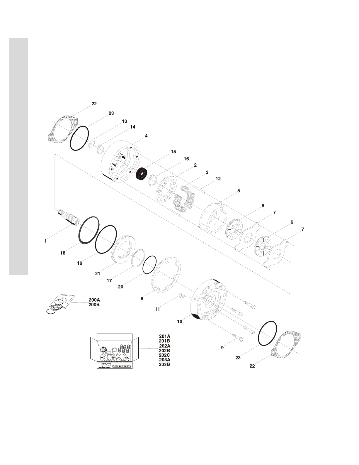
FIGURE 2-8. SWING MOTOR ASSEMBLY (PARKER)
FIG & ITEM # PART NUMBER DESCRIPTION QTY. REV.
1001110169 SWING MOTOR ASSEMBLY (PARKER) Ref. A
1 70002243 Bolt 5
2 7004035 Cover, End 1
3 Use 7024389 Seal, Commutator 1
4 Use 7024389 Seal, Ring 5
5 7024453 Commutator and Ring Assembly 1
6 Use 7024453 Ring 1
7 7024379 Manifold 1
8 70002208 Rotor Set 1
9 7024380 Plate, Wear 1
10 83304150 Link, Drive 1
11 Not Used
12 7024395 Shaft, Coupling 1
13 7024381 Bushing, Bronze 1
14 7004043 Thrustwasher 2
15 7004044 Bearing, Thrust 1
16 Use 7024389 Seal, Inner 1
17 Use 7024389 Washer, Back-up 1
18
19 7024390 Bearing 1
20 Use 7024389 Seal 1
21 to 24 Not Used
25 Use 7024389 Washer, Backup 1
100 7024389 Seal Kit (Includes Items 3, 4, 16,17, 20 & 25) 1
See Note Housing (Note: Not Available - Purchase Complete Swing
Motor Assembly.)
— — — — — — — — — —
1
S
E
C
T
I
O
N
2
T
U
R
N
T
A
B
L
E
3120795 2-25
Page 54

S
E
C
T
I
O
N
2
T
U
R
SECTION 2 3 TURNTABLE
FIGURE 2-9. DEUTZ ENGINE INSTALLATION
N
T
A
B
L
E
2-26 3120795
Page 55

SECTION 2 3 TURNTABLE
.
FIGURE 2-9. DEUTZ ENGINE INSTALLATION
FIG & ITEM # PART NUMBER DESCRIPTION QTY. REV.
0259552 DEUTZ ENGINE INSTALLATIONS (PRIOR TO
S/N 0300067081)
0272292 DEUTZ ENGINE INSTALLATIONS (S/N 0300067081 TO
S/N 0300128000)
1 2000146 Engine - Deutz F4M1011F Diesel 1
2 4845404 Tray Engine 1
3 3539872 Plate, Radiator Mounting 1
4 3620033 Cooler, Oil 1
5 2060025 Fan 1
6 Piston Pump Assembly Options (See Figure 2-11 for
Breakdown):
3600267 Prior to S/N 0300067081
3600358 S/N 0300067081 to S/N 0300070517
3600267 S/N 0300070517 to S/N 0300070643
3600363 S/N 0300070643 to S/N 0300128000
7 1340060 Air Cleaner Assembly 1
7012664 Element 1
8 0340041 Band, Mounting 2
9 4640751 Valve, Oil Drain 1
10 3600242 Gear Pump Assembly (See Figure 2-12 for Breakdown) 1
11 3200401 Mount, Rubber Engine (Rear) 2
12 3537420 Bracket, Engine Mounting - Rear 1
13 3539971 Bracket, Engine Mounting - Front 1
14 3537416 Support, Engine - Right 1
15 Support, Engine - Left Options: 1
3537417 Prior to S/N 0300067975
4846479 S/N 0300067975 to S/N 0300128000
16 0400075 Battery 1
17 0181727 Hold-Down, Battery 1
18 0630498 Rod, Hold-Down 2
19 3740067 Relay 2
20 Not Used
21 4360392 Switch, Restrictor Indicator 1
22 2180798 Fitting 1
23 3422446 Pin, Pivot 1
24 3841143 Keeper, Pin 1
25 3960389 Seal
26 0940070 Bumper, Rubber 1
27 2720398 Hose, Oil Cooler - Left 1
28 2720398 Hose, Oil Cooler - Right 1
29 1703162 Nameplate - Fan Caution 2
30 1320016 Clamp, Hose 4
31 2901392 Throttle Mounting Kit 1
31A 7008833 Bracket, Throttle 1
31B 7008835 Coupling, Ball Joint 1
31C 7008836 Spring 1
32 2220451 Fitting, Straight 2
33 3931620 Capscrew, Socket Head 3/8in-16NC x 1-1/4in 2
Ref. 5/F
Ref. 5/D
1
5ft/1.5m
S
E
C
T
I
O
N
2
T
U
R
N
T
A
B
L
E
3120795 2-27
Page 56

SECTION 2 3 TURNTABLE
FIGURE 2-9. DEUTZ ENGINE INSTALLATION (CONTINUED)
S
E
C
T
I
O
N
2
T
U
R
N
T
A
B
L
E
FIG & ITEM # PART NUMBER DESCRIPTION QTY. REV.
34 0902511 Bracket, Control Module Mounting 1
35 0641818 Bolt 1/2in-13NC x 2-1/4in 2
36 3311805 Locknut 1/2in-13NC 4
37 0641610 Bolt 3/8in-16NC x 1-1/4in 21
38 3311605 Locknut 3/8in-16NC 22
39 4751600 Flatwasher 3/8in Regular 44
40 0701414 Bolt 1/4in-20NC x 3/4in A/R
41 4891600 Flatwasher, 3/8in Hardened 2
42 0641407 Bolt 1/4in-20NC x 7/8in 12
43 4751400 Flatwasher 1/4in Regular 20
44 3311405 Locknut 1/4in-20NC 12
45 0721005 Bolt #10-24NC x 5/8in 2
46 3311005 Locknut #10-24NC 2
47 4751000 Flatwasher #10 Regular 2
48 1320022 Clamp, Hose 6
49 2220273 Fitting, Reducer 2
50 2180536 Fitting, Straight 1
51 2220313 Fitting,90° 1
52 2750532 Hose 3/8in
53 2220250 Fitting, Reducer 1
54 2220459 Fitting, 90° 1
55 2720271 Hose 3/16in
56 0641812 Bolt 1/2in-13NC x 1-1/2in 2
57 0100020 Sealant, Thread A/R
58 0100011 Compound, Locking A/R
59 Not Used
60 Coupling, Rubber Intake Options: A/R
2720351 Prior to S/N 0300067975
2720449 S/N 0300067975 to S/N 0300128000 1
61 0700808 Bolt M8 x 16mm 4
62 Use 2910000 Actuator Assembly (was p/n 0060033) (See Section 7 for
Breakdown)
63 0641508 Bolt 5/16in-18NC x 1-1/4in 3
64 0641514 Bolt 5/16in-18NC x 1-3/4in 3
65 2720434 Elbow, Rubber 1
66 4845395 Air Intake Adapter Weldment 1
67 0641510 Bolt 5/16in-18NC x 1-1/4in 3
68 3311505 Locknut 5/16in-18NC 10
69 0961986 Bushing, Flanged 2
70 2901358 Battery Cable Kit (Standard) 1
70A 7016800 Cable, Battery (Red) 1
70B 7016812 Cable, Battery (Black) 1
70C 7016802 Cable (Red) 1
70D 7016803 Cable (Red) 1
70E 7016804 Cable (Red) 1
71 4460611 Terminal, Battery Jumper Post 1
72 4360294 Breaker, Circuit - 30 Amp 1
73 1320222 J-Clip 3/8in 1
74 1320223 J-Clip 1/2in 4
6ft./1.83m
14ft./4.2m
3in./8cm
1
2-28 3120795
Page 57

SECTION 2 3 TURNTABLE
FIGURE 2-9. DEUTZ ENGINE INSTALLATION (CONTINUED)
FIG & ITEM # PART NUMBER DESCRIPTION QTY. REV.
75 0641606 Bolt 3/8in-16NC x 3/4in 3
76 Not Used
77 3790152 O-Ring 1
78 3960407 Gasket 1
79 4791400 Starwasher 1/4in 4
80 0701012 Bolt M10 x 25mm 4
81 0701015 Bolt M10 x 35mm 4
82 0642010 Bolt 5/8in-11NC x 1-1/4in 1
83 4752000 Flatwasher 5/8in Regular 1
84 1701505 Decal - Diesel (Not Shown - Located on Hood) 1
85 2720058 Hose
86 2220794 Fitting, Barbed 1
87 4711600 Flatwasher 3/8in Thin 3
88 Not Used
89 3200362 Mount, Rubber Engine (Front) 2
90 Not Used
91 3960468 Seal, Foam Gasket 1
92 3960469 Seal, Foam Gasket 1
93 Not Used
94 4060805 Flex-Trim 1/4in
95 4060804 Flex-Trim 3/16in
96 1060637 Lanyard 1
97 0641808 Bolt 1/2in-13NC x 1in 4
98 3311801 Nut 1/2in-13NC 1
99 4751800 Flatwasher 1/2in Regular 2
100 3380429 Panel, Rubber 1
101 3539957 Plate, Hold Down 2
102 Not Used
103 4847815 Tuning Tube Weldment 1
104 Not Used
105 0641826 Bolt 1/2in-13NC x 3-1/4in 2
106 4740274 Washer, Snubbing 4
107 Piston Pump Assembly Options (See Figure 2-11 for
Breakdown):
3600268 Prior to S/N 0300067081
3600359 S/N 0300067081 to S/N 0300128000
108 3790045 O-Ring 1
109 4711900 Flatwasher 9/16in Thin (S/N 0300067975 to S/N 0300128000) 6
16ft/4.9m
7in/18cm
16in/40cm
1
S
E
C
T
I
O
N
2
T
U
R
N
T
A
B
L
E
3120795 2-29
Page 58

SECTION 2 3 TURNTABLE
FIGURE 2-9. DEUTZ ENGINE INSTALLATION (CONTINUED)
S
E
C
T
I
O
N
2
T
U
R
N
T
A
B
L
E
FIG & ITEM # PART NUMBER DESCRIPTION QTY. REV.
MUFFLER INSTALLATION - STANDARD MACHINES Ref.
0256689 Standard Equipment (Spark Arresting) Ref.
0256690 Optional Equipment (Catalytic) Ref.
201 Muffler Options: 1
3220103 Standard Spark Arresting
3220104 Optional Catalytic
1320176 Clamp, Saddle (3220103 Muffler) (Not Shown) 1
70001017 Clamp, Band (3220104 Muffler) (Not Shown) 1
7024398 Pipe, Exhaust 1
7024560 Plug, Brass (Not Shown) 1
7020471 Gasket, Exhaust Manifold to Engine Block (Not Shown) 4
70002200 Stud, Exhaust Manifold to Engine Block (Not Shown) 8
70003476 Nut, Exhaust Manifold to Engine Block (Not Shown) 8
7000699 Gasket, Doughnut (Not Shown) 1
2000146 ENGINE COMPONENTS Ref.
301 7016639 Fuel Filter Assembly with Water Drain 1
Use 8320270 Filter, Fuel (was p/n 7016328) 1
302 Use 7000663 Alternator (was p/n 7016329, 7020436 & 7020410) 1
70002234 Bar, Adjustment 1
303 7016330 Switch, Oil Pressure (Not Shown) 1
304 7016331 Filter, Oil (was p/n 7016641) 1
70002813 Seal (Between Filter Head & Engine Block) 1
305 7016332 Starter 1
306 7026631 Dipstick Kit - Engine Oil (Includes Dipstick, Dipstick Tube &
Clamp) (was p/n 7019664) (Not Shown)
70001002 Tube, Dipstick (Not Shown)
307 7020025 Switch, Oil Temperature (Not Shown) 1
308 7020414 V-Belt 1
309 Gasket, Head Options (Not Shown): 1
70001681 Gasket with 1 Notch
70002411 Gasket with 2 Notches
70002530 Gasket with 3 Notches
310 7020463 Pump, Fuel Supply 1
7020432 Repair Kit - Fuel Pump 1
7020411 O-Ring 1
311 Use 7019607 Shutdown Device (was p/n 7016359) 1
7027250 Spring, Tension 1
312 70001687 Module, Glow Plug Timer Control (Not Shown) 1
313 7026522 Injector, Fuel (Includes Nozzle) 4
7020425 Nozzle, Injector 4
7020424 Ring, Injector Sealing 4
7012599 Pump, Injection 4
314 7020465 Cap, Oil Fill (Not Shown) 1
315 7020027 Flywheel/Ring Gear Assembly (Not Shown) 1
7020477 Ring Gear (Not Shown) 1
316 7020419 Hose, Fuel Return (Not Shown) 1
317 7020431 Gasket, Valve Cover (Not Shown) 1
1
2-30 3120795
Page 59

SECTION 2 3 TURNTABLE
FIGURE 2-9. DEUTZ ENGINE INSTALLATION (CONTINUED)
FIG & ITEM # PART NUMBER DESCRIPTION QTY. REV.
0256847 PUMP COUPLING INSTALLATION Ref.
401 1660234 Coupling, Hayes 1
402 0080163 Plate, Pump Adapter 1
403 0700810 Bolt M8 x 20mm 6
404 4831900 Lockwasher M8 6
405 Not Used
406 4832000 Lockwasher M10 8
407 3020021 Grease, Coupling A/R
S
E
C
T
I
O
N
2
T
U
R
N
T
A
B
L
E
3120795 2-31
Page 60
S
USE
EXISTING
HARDWARE
OR
10
9
9
101010
1010161711
5
1
2021222B152C192D1423202222
21
2
2
2A
S/N 00300067975
TO S/N 0300128000
7
10
12
4B
3B
PRIOR TO
S/N 00300067975
9
10
13
17
12
4A
6
8
7
3A
9
13
8
E
C
T
I
O
N
2
T
U
R
SECTION 2 3 TURNTABLE
FIGURE 2-10. GENERATOR INSTALLATION - DEUTZ MACHINES (OPTIONAL)
N
T
A
B
L
E
2-32 3120795
Page 61

SECTION 2 3 TURNTABLE
.
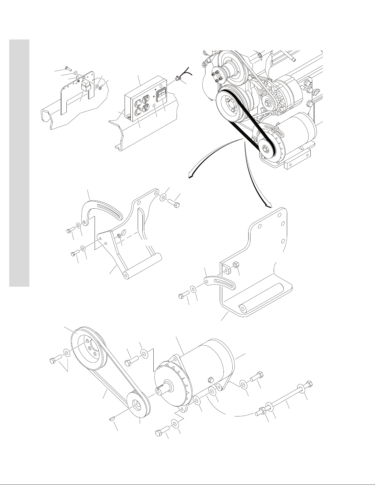
FIGURE 2-10. GENERATOR INSTALLATION - DEUTZ MACHINES (OPTIONAL)
FIG & ITEM # PART NUMBER DESCRIPTION QTY. REV.
GENERATOR INSTALLATION OPTIONS: Ref.
0257853 110V Generator (Prior to S/N 0300067975) Ref. 3
0272417 110V Generator (S/N 0300067975 to S/N 0300128000) Ref. 1
0257857 220V Generator (Prior to S/N 0300067975) Ref. 4
1 3580158 Pulley 1
2 Generator and Control Box Assembly Options: 1
2460011 110V (Prior to S/N 0300067975)
2460032 110V (S/N 0300067975 to S/N 0300128000)
2460013 220V
2A Generator Options: 1
7012558 110V
1001100321 220V
Note: Replacement Generators come standard
with p/n 3580134 pulley. This pulley may not
be correct for all applications. Refer to
pulley options below.
Armature with Slip Rings Options: 1
7026199 110V 1
70000123 220V 1
7012513 Cap, Brush Holder 4
7020108 Brush 4
7020109 Holder, Brush 4
7012514 Fan 1
7020190 Bearing 2
7020110 End Bell, Front 1
7020111 End Bell, Rear 1
2B Control Box Options: 1
7003657 110V
70002235 220V
Breaker, Circuit Options: 1
4360542 110V
70000126 220V
4460190 Receptacle, Double (110V) 2
70000124 Receptacle, Double (220V) 1
70000125 Receptacle, Single Twist Lock (220V) 1
2920162 Lamp Assembly 1
7020191 Switch, Toggle 1
2C Voltmeter Options: 1
2420203 110V 1
7020192 220V 1
2D Pulley Options: 1
3580134 110V (Prior to S/N 0300067975)
3580276 110V (S/N 0300067975 to S/N 0300128000)
3580134 220V
7027887 Key, Woodruff 1
3 Bracket, Generator Mounting Options: 1
3A Use 4845531 Prior to S/N 0300034200 (was p/n 4845184)
4845531 S/N 0300034200 to S/N 0300067975
Ref.
S
E
C
T
I
O
N
2
T
U
R
N
T
A
B
L
E
3120795 2-33
Page 62

S
E
C
T
I
O
N
2
T
U
R
N
T
A
B
L
E
SECTION 2 3 TURNTABLE
FIGURE 2-10. GENERATOR INSTALLATION - DEUTZ MACHINES (OPTIONAL) (CONTINUED)
FIG & ITEM # PART NUMBER DESCRIPTION QTY. REV.
3B 4846479 S/N 0300067975 to S/N 0300128000
(Part of Engine Assembly)
4 Arm, Adjusting Options: 1
4A 0200530 Prior to S/N 0300067975
4B 0200741 S/N 0300067975 to S/N 0300128000
5 V-Belt Options: 1
0480050 Prior to S/N 0300067975
0480111 S/N 0300067975 to S/N 0300128000
6 0711414 Bolt M14 x 30mm A/R
7 Hardware Options: A/R
4751900 Flatwasher 9/16in Regular (Prior to S/N 0300067975) 2
0641610 Bolt 3/8in-16NC x 1-1/4in (S/N 0300067975 to
S/N 0300128000)
8 0100011 Compound, Locking A/R
9 Bolt Options: A/R
0681612 Bolt 3/8in-16NC x 1-1/2in (Prior to S/N 0300067975) 3
0641772 Bolt 7/16in-14NC x 9in (S/N 0300067975 to
S/N 0300128000)
10 4751600 Flatwasher 3/8in Regular 6
11 2860012 Key, Woodruff 1
12 3311605 Locknut 3/8in-16NC 1
13 Hardware Options: A/R
0700819 Bolt M8 x 55mm (Prior to S/N 0300064395) 1
3311705 Locknut 7/16in-14NC (S/N 0300064395 to
S/N 0300128000)
14 3740080 Relay 1
15 4460023 Connector, Strain Relief 1
16 0641508 Bolt 5/16in-18NC x 1in 1
17 4751500 Flatwasher 5/16in Regular 2
18 Not Used
19 3520028 Plug, Hole 1
20 0721006 Bolt #10-24NC x 3/4in 4
21 3311005 Locknut #10-24NC 4
22 4751000 Flatwasher #10 Regular 9
23 4360294 Breaker, Circuit - 30 Amp 1
24 Not Used
25 4360336 Switch, Toggle (Not Shown - Located at Platform) 1
26 4740397 Bushing (Not Shown - Located at Platform) 1
27 4060802 Guard, Switch (Not Shown - Located at Platform) 1
28 Not Used
29 2820031 Heatshrink (Not Shown - Located at Platform)
30 3251102 Decal (Not Shown - Located at Platform) 1
1
1
1
4in/10cm
2-34 3120795
Page 63

SECTION 2 3 TURNTABLE
FIGURE 2-10. GENERATOR INSTALLATION - DEUTZ MACHINES (OPTIONAL) (CONTINUED)
FIG & ITEM # PART NUMBER DESCRIPTION QTY. REV.
S
E
C
T
I
O
N
2
T
U
R
N
T
A
B
L
E
3120795 2-35
Page 64

S
42
10
9
8
7
5
6
4
27
37
38
65
61
62
63
64
32
114
115
1
3
2
33
29
30
26
28
91
90
87
88
89
38
37
36
40
39
OR
OR
85
858484
222318
17
1516317071
72
736869
101
67
66
31
100
100
99
99
98
98
97
95
96
94
92
93
58
58
59
59
60
60
57
57
53
55
34
11035111
54
56
14
13
12
11
24
19
20
21
REAR
PUMP
104
106
105
107
107
108
108
109
109
FRONT
PUMP
8382817980
75
7677788674
125
41
52434445112
113
1034746
10248495051
25
103
E
C
T
SECTION 2 3 TURNTABLE
FIGURE 2-11. PISTON PUMP ASSEMBLY
I
O
N
2
T
U
R
N
T
A
B
L
E
2-36 3120795
Page 65

SECTION 2 3 TURNTABLE
.
FIGURE 2-11. PISTON PUMP ASSEMBLY
FIG & ITEM # PART NUMBER DESCRIPTION QTY. REV.
PISTON PUMP ASSEMBLIES Ref.
3600267 Front Pump (15 Tooth) (Prior to S/N 0300067081) Ref. D
3600358 Front Pump (15 Tooth) (S/N 0300067081 to
S/N 0300070517)
3600267 Front Pump (15 Tooth) (S/N 0300070517 to
S/N 0300070643)
3600363 Front Pump (15 Tooth) (S/N 0300070643 to
S/N 0300128000)
3600268 Rear Pump (13 Tooth) (Prior to S/N 0300067081) Ref. D
3600359 Rear Pump (13 Tooth) (S/N 0300067081 to
S/N 0300128000)
1 Cam Follower Bearing Assembly Options (Includes Item 3): 1
7021234 Used with p/n 3600267/3600268
7024805 Used with p/n 3600358/3600359/3600363
2 7022330 Swashplate 1
3 7021236 Bearing, Needle 1
4 Shaft Options: 1
7021237 Front Pump (15 Tooth)
7022354 Rear Pump (13 Tooth)
5 7021238 Ring, Retaining 1
6 7021239 Bearing, Roller 1
7 Shaft Options (Includes Items 4, 5 & 6): 1
7021240 Front Pump (15 Tooth)
7022355 Rear Pump (13 Tooth)
8 Use 7021280 O-Ring 1
9 Use 7021280 Seal, Lip 1
10 7021243 Carrier, Shaft Seal 1
11 7023996 Screw 1
12 7022331 Link, Control Summing 1
13 7022332 Link, Control Feedback 1
14 7022333 Link, Neutral Adjust 1
15 7022334 Screw, Neutral Adjust 1
16 7023997 Nut, Seal 1
17 7022321 Plug (Includes Item 18) 1
18 Use 7021280 O-Ring 1
19 7022335 Control Kit (Includes Items 20 & 21) 1
20 7023998 Screw 4
21 7021267 Screw 3
22 7022336 Spool Assembly 1
23 7022337 Spring 1
24 7022338 Gasket, Control 1
25 Housing Assembly (Includes Items 27, 32, 36 & 41): 1
7022339 Front Pump (Used with p/n 3600267)
7023999 Front Pump (Used with p/n 3600358/3600363)
7022356 Rear Pump (Used with p/n 3600268)
Use 3600359 Rear Pump (Used with p/n 3600359) (Note: Not
Available - Purchase Complete Rear Pump.)
26 7021248 Side Cover Assembly 1
Ref. A
Ref. D
Ref. B
Ref. A
S
E
C
T
I
O
N
2
T
U
R
N
T
A
B
L
E
3120795 2-37
Page 66

SECTION 2 3 TURNTABLE
FIGURE 2-11. PISTON PUMP ASSEMBLY (CONTINUED)
S
E
C
T
I
O
N
2
T
U
R
N
T
A
B
L
E
FIG & ITEM # PART NUMBER DESCRIPTION QTY. REV.
27 7021249 Bearing, Needle 1
28 7021250 Pin 1
29 7021251 Screw 2
30 Use 7021280 Gasket, Side Cover 1
31 7021253 Gasket, Servo Cover 2
32 7021254 Screen, Filter (Used with p/n 3600267/3600268) 1
33 7021255 Screw 4
34 7022321 Plug (Includes Item 35) 1
35 Use 7021280 O-Ring 1
36 Plug 1
7001485 Front Pump
Not Required Rear Pump
37 7007419 Plug (Includes Item 38) 2
38 Use 7021280 O-Ring 2
39 7007470 Plug (Includes Item 40) 2
40 Use 7021280 O-Ring 2
41 7001485 Plug, Pipe 2
42 7021257 Ring, Retaining 1
43 7022340 Bracket, Lifting 1
44 7021251 Screw 1
45 7022342 Key 1
46 7022341 Ring, Retaining 1
47 Component Options: 1
7022343 Gerotor Assembly (Front Pump)
7022357 Spacer (Rear Pump)
48 7021259 Bearing, Journal 1
49 Cover Assembly (Gerotor) Options (Includes Item 48): 1
7022344 Front Pump
7022360 Rear Pump (Used with p/n 3600268)
7021260 Rear Pump (Used with p/n 3600359)
50 See Note O-Ring (Note: No longer required per supplier.
Pressure is the same on either side of o-ring.)
51 Use 7021280 O-Ring 1
52 See Note Pin (Note: Not Available for Purchase.) 1
53 7022345 Valve, SCR 1
54 Spring Options: 1
7021264 Used with p/n 3600267/3600268
7024800 Used with p/n 3600358/3600359/3600363
55 7022345 Valve, SCR 1
56 Spring Options: 1
7021264 Used with p/n 3600267/3600268
7024800 Used with p/n 3600358/3600359/3600363
57 7021265 Bypass Valve Assembly (Includes Items 58, 59 & 60) 2
58 Use 7021280 O-Ring 2
59 Use 7021280 Ring, Back-up 2
60 Use 7021280 O-Ring 2
61 7022346 Adjuster 1
62 7021289 O-Ring 1
63 7022347 Spring 1
1
2-38 3120795
Page 67

SECTION 2 3 TURNTABLE
FIGURE 2-11. PISTON PUMP ASSEMBLY (CONTINUED)
FIG & ITEM # PART NUMBER DESCRIPTION QTY. REV.
64 Poppet Options: 1
See Note Used with p/n 3600267/3600268 (Note: Not Available
for Purchase.)
7024804 Used with p/n 3600358/3600359/3600363
65 7022190 Nut 1
66 7022348 Cover, Servo 1
67 7021255 Screw, Torx 5
68 7007470 Plug (Includes Item 69) 1
69 Use 7021280 O-Ring 1
70 7001268 Cover, Servo 1
71 7021255 Screw, Torx 5
72 7007470 Plug (Includes Item 73) 1
73 Use 7021280 O-Ring 1
74 Cylinder Block Kit Options (Includes Items 75 to 83): 1
7022349 Front Pump (With Speed Ring)
7021269 Rear Pump (Without Speed Ring)
75 7021271 Washer, Special 1
76 7021272 Spring, Cylinder Block 1
77 7021273 Washer, Special 1
78 7021274 Ring, Retaining 1
79 7021275 Pin, Slipper Hold Down 3
80 7021276 Retainer, Pin 1
81 7021277 Guide, Retainer 1
82 7021278 Retainer, Slipper 1
83 7021279 Piston Assembly 9
84 Component Options (Includes Item 85): 1
7022350 Sensor, Speed (Front Pump)
7007470 Plug (Rear Pump)
85 Use 7021280 O-Ring 1
86 7021281 Plate, Valve (Right Side) 1
87 7007470 Plug (Includes Item 88) (Front Pump Only) 1
88 Use 7021280 O-Ring (Front Pump Only) 1
89 Spool, Loop Flushing Options: 1
7021282 Used with p/n 3600267/3600363
7024801 Used with p/n 3600358/3600359
90 7021283 Plug (Includes Item 91) (Front Pump Only) 1
91 Use 7021280 O-Ring (Front Pump Only) 1
92 7021285 Adapter, Remote Filter (Front Pump Only) 1
93 Use 7021280 Gasket, Filter Adapter (Front Pump Only) 1
94 7021255 Screw (Front Pump Only) 7
95 7007470 Plug (Includes Item 96) 1
96 Use 7021280 O-Ring 1
97 7022351 Servo Piston Kit (Includes Qty 2 of Item 98) 1
98 7007412 Servo Piston Ring Kit (Includes Items 99 & 100) 2
99 Use 7021280 O-Ring 2
100 Use 7021280 Ring, Piston 2
101 Use 7021280 Nut, Seal 1
S
E
C
T
I
O
N
2
T
U
R
N
T
A
B
L
E
3120795 2-39
Page 68

SECTION 2 3 TURNTABLE
FIGURE 2-11. PISTON PUMP ASSEMBLY (CONTINUED)
S
E
C
T
I
O
N
2
T
U
R
N
T
A
B
L
E
FIG & ITEM # PART NUMBER DESCRIPTION QTY. REV.
102 Coupling Options: 1
7022352 Front Pump
7022359 Rear Pump
103 7001481 Pin 2
104 Use 7021280 Gasket, Charge Pump 1
105 7021296 Screw, Torx 6
106 Cover, Charge Pump 1
7022353 Front Pump
7021297 Rear Pump
107 Seal Options: 1
Use 7021280 O-Ring (Front Pump)
7021298 Seal (Rear Pump)
108 Cover, Flange Options: 1
7021229 Front Pump
7021299 Rear Pump
109 7007289 Screw 2
110 7007419 Plug (Rear Pump Only) 1
111 Use 7021280 O-Ring (Rear Pump Only) 1
112 7022358 Plug (Include Item 113) (Rear Pump Only) 1
113 Use 7021280 O-Ring (Rear Pump Only) 1
114 Plug Options (Include Item 115) (Rear Pump Only): 1
7021283 Used with p/n 3600268 1
7021256 Used with p/n 3600359 1
115 Use 7021280 O-Ring (Rear Pump Only) 1
116 7024802 Spring (Used with p/n 3600358/3600359 Only) 1
117 7024803 Poppet (Used with p/n 3600358/3600359 Only) 1
118 to 124 Not Used
125 7021280 Seal Kit - Complete (Includes Items 8, 9, 16, 18, 30, 31, 35,
38, 40, 51, 58, 59, 60, 69, 73, 85, 88, 91, 93, 96, 99, 100,
101, 104, 107, 111,113 & 115)
1
2-40 3120795
Page 69

SECTION 2 3 TURNTABLE
FIGURE 2-11. PISTON PUMP ASSEMBLY (CONTINUED)
FIG & ITEM # PART NUMBER DESCRIPTION QTY. REV.
S
E
C
T
I
O
N
2
T
U
R
N
T
A
B
L
E
3120795 2-41
Page 70

S
20
6
1
12
4
5
2
11
3
9
8
7
13
10
E
C
T
I
O
N
2
T
U
R
SECTION 2 3 TURNTABLE
FIGURE 2-12. GEAR PUMP ASSEMBLY
N
T
A
B
L
E
2-42 3120795
Page 71

SECTION 2 3 TURNTABLE
.
FIGURE 2-12. GEAR PUMP ASSEMBLY
FIG & ITEM # PART NUMBER DESCRIPTION QTY. REV.
3600242 GEAR PUMP ASSEMBLY Ref.
1 7010105 Bearing/Bushing 2
2 See Note Housing (Note: Not Available - Purchase Complete Gear
Pump Assembly.)
3 See Note Flange (Note: Not Available - Purchase Complete Gear
Pump Assembly.)
4 7010103 Cover 1
5 7012987 Gear, Drive 1
6 7012988 Gear, Idler 1
7 Use I7007489 Ring, Anti-Extrusion 2
8 Use I7007489 Seal 2
9 See Note Bolt (Note: Not Available for Purchase.)
10 7010104 Ring, Retaining 1
11 See Note Pin, Dowel (Note: Not Available for Purchase.)
12 Use I7007489 Seal, O-Ring 2
13 Use I7007489 Seal, Shaft 1
14 to 19 Not Used
20 7007489 Seal Kit (Includes Items 7,8,12 & 13) 1
1
1
S
E
C
T
I
O
N
2
T
U
R
N
T
A
B
L
E
3120795 2-43
Page 72

S
E
C
T
I
O
N
2
T
U
R
SECTION 2 3 TURNTABLE
FIGURE 2-13. TANK INSTALLATIONS
N
T
A
B
L
E
2-44 3120795
Page 73

SECTION 2 3 TURNTABLE
.
FIGURE 2-13. TANK INSTALLATIONS
FIG & ITEM # PART NUMBER DESCRIPTION QTY. REV.
TANKS INSTALLATION OPTIONS: Ref.
0254849 Standard Without Locking Fuel Tank Ref. 9
0257483 Optional With Locking Fuel Tank Ref. 2
1 Hydraulic Tank Assemblies Options: 1
4400375 Prior to S/N 0300068129 (See Items 101-104 for Break-
down)
4400449 S/N 0300068129 to S/N 0300128000 (See Items 201-
207 for Breakdown)
2 4400400 Tank, Fuel 1
2A 7019658 Tube, Fuel Pick-up 1
2B Cap Options: 1
7016314 Standard - Non-Locking
1120487 Optional Locking (Blue - Diesel Machines) (Not Included
with Tank)
3 4360436 Switch, Fuel Level 1
4 4845393 Hydraulic Tray Weldment 1
5 4240112 Strap, Tank (Prior to S/N 0300068129) 4
6 4240113 Strap, Tank 1
7 4751600 Flatwasher 3/8in Regular 12
8 3311601 Nut 3/8in-16NC A/R
9 0641614 Bolt 3/8in-16NC x 1-3/4in 6
10 0100011 Compound, Locking A/R
11 0100079 Sealant, Pipe A/R
12 2200222 Fitting 1
13 4280295 Strip, Protective
14 4420038 Tape, Rubber
15 0641608 Bolt 3/6in-16NC x 1in (S/N 0300068129 to
S/N 0300128000)
25in/44cm
70in/1.78m
4
S
E
C
T
I
O
N
2
T
U
R
N
T
A
B
L
E
4400375 HYDRAULIC TANK ASSEMBLY (PRIOR TO S/N 0300068129) Ref. F
101 7014810 Filler/Breather Assembly 1
7014811 Cap, Breather 1
102 7014802 Gauge, Sight 1
103 7014801 Strainer 1-1/4inNPT 1
104 7014800 Plug, Magnetic 1
4400449 HYDRAULIC TANK ASSEMBLY (S/N 0300068129 TO
S/N 0300128000)
201 7024444 Filler/Breather Assembly 1
202 7024441 Gauge, Sight 1
203 7024442 Strainer 1-1/4inNPT 2
204 7024446 Plug, Magnetic 1
205 7024445 Strainer 1
206 7024443 Neck, Filler 1
207 7024439 Cover 1
7024440 Gasket 1
3120795 2-45
Ref. B
Page 74

S
E
C
T
I
O
N
2
T
U
R
SECTION 2 3 TURNTABLE
FIGURE 2-14. ROTARY COUPLING INSTALLATION
N
T
A
B
L
E
2-46 3120795
Page 75

SECTION 2 3 TURNTABLE
.
FIGURE 2-14. ROTARY COUPLING INSTALLATION
FIG & ITEM # PART NUMBER DESCRIPTION QTY. REV.
ROTARY COUPLING ASSEMBLY Ref.
1660243 Prior to S/N 0300064782 Ref. D
1660245 S/N 0300064782 to S/N 0300128000 Ref. A
1 7022720 Bolt M10 x 25mm 6
2 7022721 Washer 2
3 7022722 Cover 1
4 7022723 O-Ring 1
5 7022724 Retainer 1
6 Housing Options: 1
7022725 Prior to S/N 0300064782
7022735 S/N 0300064782 to S/N 0300128000
7 7022726 Seal A/R
8 7022727 O-Ring 3
9 Rotor Options: 1
7022728 Prior to S/N 0300064782
7022736 S/N 0300064782 to S/N 0300128000
10 7022729 Plug, Pipe 1
11 7022730 O-Ring 1
12 7022731 Plug, O-Ring 1
ROTARY COUPLING INSTALLATIONS Ref.
0259694 Prior to S/N 0300064782 Ref. E
0271915 S/N 0300064782 to S/N 0300128000 Ref. B
101 0100011 Compound, Locking A/R
102 0641611 Bolt 3/8in-16NC x 1-3/8in 2
103 0701012 Bolt, Metric M10 x 25mm 4
104 Bracket Options: 1
Use 0902814 Prior to S/N 0300062876 (was p/n 0902591)
Use 0902814 S/N 0300062876 to S/N 0300067081 (was p/n 0902738)
0902814 S/N 0300067081 to S/N 0300128000
105 Rotary Coupling Assembly Options (See Items 1-12 for
Breakdown):
1660243 Prior to S/N 0300064782
1660245 S/N 0300064782 to S/N 0300128000
106 3841456 Rod, Coupling 1
107 4740490 Washer, Special 1
108 4751600 Flatwasher 3/8in Regular 6
1
S
E
C
T
I
O
N
2
T
U
R
N
T
A
B
L
E
3120795 2-47
Page 76
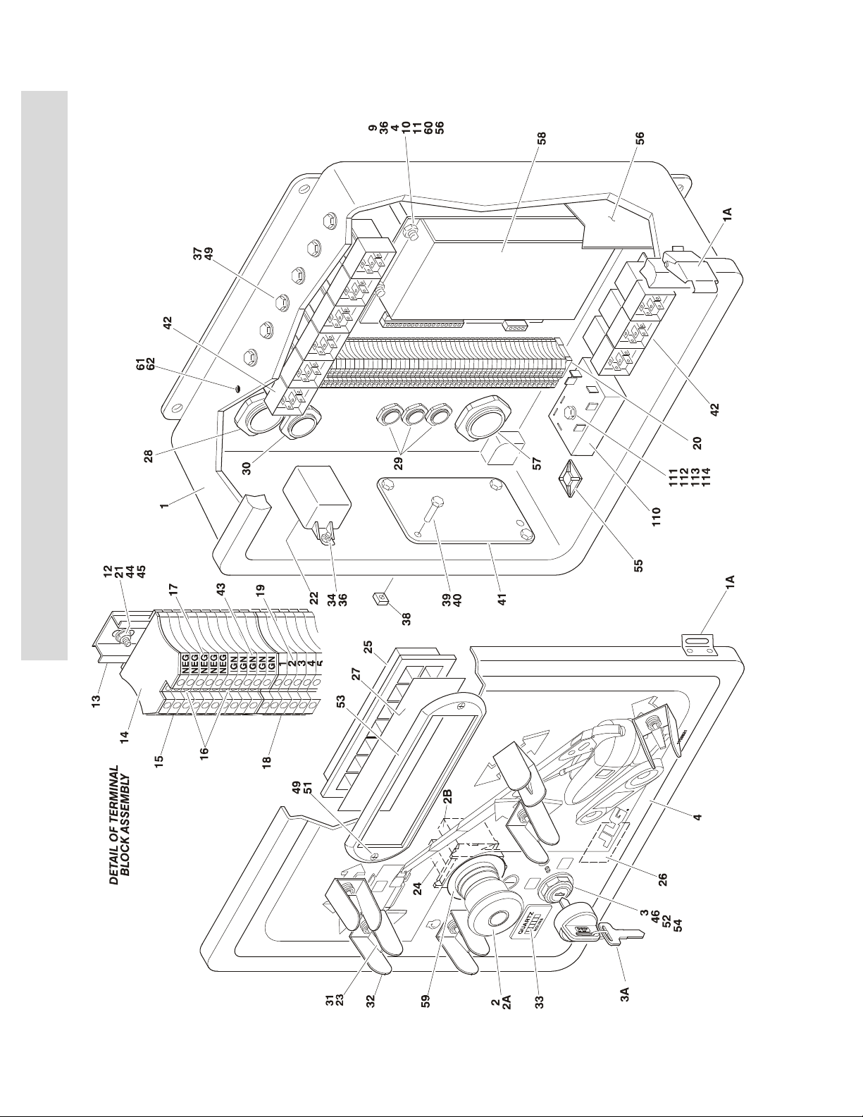
S
E
C
T
I
O
N
2
T
U
R
SECTION 2 3 TURNTABLE
FIGURE 2-15. GROUND CONTROL BOX ASSEMBLY
N
T
A
B
L
E
2-48 3120795
Page 77

SECTION 2 3 TURNTABLE
.
FIGURE 2-15. GROUND CONTROL BOX ASSEMBLY
FIG & ITEM # PART NUMBER DESCRIPTION QTY. REV.
GROUND CONTROL BOX ASSEMBLIES Ref.
0861322 600SC (Prior to S/N 0300064782) Ref. 5
0861513 600SC (S/N 0300064782 to S/N 0300128000) Ref. 1
0861108 600SJC & 660SJC (Prior to S/N 0300064782) Ref. 5
0861514 600SJC & 660SJC (S/N 0300064782 to S/N 0300128000) Ref. 2
1 0861112 Box, Fiberglass 1
1A 7020246 Latch 2
2 4360475 Switch, Emergency Stop 1
2A 7020175 Cap, Red 1
2B 7020176 Contact Block
3 4360469 Switch, Key 1
3A 2860030 Key Replacement 1
4 Decal - Faceplate Options: 1
1703521 600SC
1704436 600SJC & 660SJC
5 Engine Harness Assembly Options (Not Shown - See
Section 7 for Breakdown):
4922330 Prior to S/N 0300064782
4922554 S/N 0300064782 to S/N 0300128000
6 4921923 Valve Harness Assembly (Not Shown - See Section 7 for
Breakdown)
7 Not Used
8 0731005 Screw #10-32NF x 5/8in 4
9 3321001 Nut #10-32NF 4
10 4761000 Lockwasher #10 4
11 4751400 Flatwasher 1/4in Regular 8
12 3910608 Screw #6-32NC x 1/2in 2
13 3640970 Rail 1
14 4460602 Barrier, Terminal 1
15 4460601 Block, Terminal 10
16 4460603 Bussbar - 10 Position (Requires being cut into (2) 5 position
bussbars)
17 4460631 Marker, Terminal (Negative) 1
18 4460600 Block, Terminal 48
19 4460628 Marker, Terminal (1-50) 2
20 4460607 Stop, Terminal 1
21 4750600 Flatwasher #6 Regular 4
22 3740112 Relay, Bosch 1
23 4360314 Switch, Toggle A/R
24 4360476 Switch, Contact Block 1
25 2760105 Housing, Display Light 1
26 4420038 Insulation, Adhesive Foam
27 Decal - Ground Control Display Options: 1
1702610 Prior to S/N 0300064782
1704704 S/N 0300064782 to S/N 0300128000
28 4460526 Connector, Strain Relief 1
29 4460428 Connector, Strain Relief 3
30 4460426 Connector, Strain Relief 1
1
1
1
4in/10cm
S
E
C
T
I
O
N
2
T
U
R
N
T
A
B
L
E
3120795 2-49
Page 78

SECTION 2 3 TURNTABLE
FIGURE 2-15. GROUND CONTROL BOX ASSEMBLY (CONTINUED)
S
E
C
T
I
O
N
2
T
U
R
N
T
A
B
L
E
FIG & ITEM # PART NUMBER DESCRIPTION QTY. REV.
31 4740444 Washer, Special A/R
32 4060906 Shield, Toggle Switch A/R
33 2420172 Gauge, Hourmeter 1
34 0721005 Screw #10-24NC x 5/8in 2
35 Not Used
36 4751000 Flatwasher #10 Regular 8
37 3900268 Screw #10-24NC A/R
38 3300205 Nut, Retainer 4
39 0641506 Bolt 5/16in-18NC x 3/4in 4
40 0100011 Compound, Locking A/R
41 3539219 Plate, Reinforcement 1
42 3740049 Relay - SPDT A/R
43 4460630 Marker, Terminal (Ignition) 1
44 4760600 Lockwasher #6 4
45 3310601 Nut #6-32NC 2
46 4070987 Shim 1
47 to 48 Not Used
49 3300408 Locknut, Plastic Insert A/R
50 Not Used
51 0630464 Capscrew, Button Head 2
52 4070991 Shim (.125) 1
53 1670829 Bezel 1
54 3910804 Screw #8-32NC x 1/4in 7
55 4460234 Base, Tie-Strap 6
56 1703622 Decal - Service Manual Reference 1
57 4460711 Connector, Strain Relief 1
58 1600262 Controller, OEM 1
59 1704260 Decal - Emergency Stop (Prior to S/N 0300064782) 1
60 4300142 Stud, Stand-Off 4
61 3520174 Plug 3
62 0100009 Adhesive A/R
GENERATOR OPTION COMPONENTS Ref.
101 to 109 Not Used
110 3740118 Relay, Timer 1
111 3911024 Screw #10-24NC x 1-1/2in 1
112 4751000 Flatwasher #10 Regular 2
113 4761000 Lockwasher #10 1
114 3311001 Nut #10-24NC 1
2-50 3120795
Page 79

SECTION 2 3 TURNTABLE
FIGURE 2-15. GROUND CONTROL BOX ASSEMBLY (CONTINUED)
FIG & ITEM # PART NUMBER DESCRIPTION QTY. REV.
S
E
C
T
I
O
N
2
T
U
R
N
T
A
B
L
E
3120795 2-51
Page 80

S
E
C
T
I
O
N
2
T
U
R
SECTION 2 3 TURNTABLE
FIGURE 2-16. ELECTRICAL OPTIONS INSTALLATION (TURNTABLE MOUNTED)
N
T
A
B
L
E
2-52 3120795
Page 81

SECTION 2 3 TURNTABLE
.
FIGURE 2-16. ELECTRICAL OPTIONS INSTALLATION (TURNTABLE MOUNTED)
FIG & ITEM # PART NUMBER DESCRIPTION QTY. REV.
ELECTRICAL OPTIONS INSTALLATIONS (TURNTABLE
MOUNTED)
LIMIT SWITCH INSTALLATION - DRIVE DISABLE Ref.
0270313 600SC & 600SCJ Ref. 4
0270381 660SJC Ref. 4
1 Use 4360578 Switch, Limit (Prior to S/N 0300074441 - was
p/n 4360322 & p/n 4360549)
2 Connector, Strain Relief Options: 2
4460428 Used on Limit Switch p/n 4360322
4460968 Used on Limit Switch p/n 4360549 & p/n 4360578
3 0100035 Compound, Locking A/R
4 3930816 Capscrew, Socket Head #8-32NC x 1in 2
5 3930828 Capscrew, Socket Head #8-32NC x 1-3/4in 2
6 3310801 Locknut #8-32NC 2
7 4420060 Tape, Double Sided
8 Bar, Fiberglass Options: 1
Use 1001106479
Use 1001106484
9 1670824 Cover, Limit Switch 1
10 4751400 Flatwasher 1/4in Regular 4
11 Not Used
12 0641408 Bolt 1/4in-20NC x 1in 4
13 3572415 Cover 1
14 to 15 Not Used
16 0100011 Compound, Locking A/R
600SC & 600SCJ (was p/n 0362528)
660SCJ (was p/n 0362951)
Ref.
2
8.7ft/2.7m
S
E
C
T
I
O
N
2
T
U
R
N
T
A
B
L
E
LIMIT SWITCHES INSTALLATION - TRANSPORT Ref.
0256305 600SC & 660SCJ Ref. 2
0256306 600SJC Ref. 2
101 Use 4360578 Switch, Limit (Prior to S/N 0300074441 - was
p/n 4360322 & p/n 4360549)
102 Connector, Strain Relief Options: 1
4460428 Used on Limit Switch p/n 4360322
4460968 Used on Limit Switch p/n 4360549 & p/n 4360578
103 0100035 Compound, Locking A/R
104 3930816 Capscrew, Socket Head #8-32NC x 1in 2
105 Bar, Fiberglass Options: 1
Use 1001106481
Use 1001106482
106 4420054 Tape, Double Sided A/R
107 4751400 Flatwasher 1/4in Regular 4
108 3931403 Capscrew, Socket Head 1/4in-20NC x 3/8in 4
109 1670824 Cover, Limit Switch 1
3120795 2-53
600SC/660SJC (was p/n 0362609)
600SCJ (was p/n 0362610
600SC & 660SCJ
600SCJ
1
17.1ft/5.2m
15ft/4.6m
Page 82

SECTION 2 3 TURNTABLE
FIGURE 2-16. ELECTRICAL OPTIONS INSTALLATION (TURNTABLE MOUNTED) (CONTINUED)
S
E
C
T
I
O
N
2
T
U
R
N
T
A
B
L
FIG & ITEM # PART NUMBER DESCRIPTION QTY. REV.
0257882 LIMIT SWITCHES INSTALLATION - 8METER (JAPANESE
SPEC OPTION ONLY) (PRIOR TO S/N 0300064251)
201 Use 4360578 Switch, Limit (Prior to S/N 0300074441 - was
p/n 4360322 & p/n 4360549)
202 Connector, Strain Relief Options: 1
4460428 Used on Limit Switch p/n 4360322
4460968 Used on Limit Switch p/n 4360549 & p/n 4360578
203 3930828 Capscrew, Socket Head #8-32NC x 1-3/4in 2
204 3310805 Locknut #8-32NC 2
205 1060016 Cable, Electrical - 16/3 (Not Shown)
206 Not Used
207 4751400 Flatwasher 1/4in Regular 2
208 3931408 Bolt 1/4in-20NC x 1/2in 2
209 1670821 Cover, Limit Switch 1
0257886 ALARMS INSTALLATIONS Ref. 1
301 0257887 Alarm/Harness Assembly 1
302 0641406 Bolt 1/4in-20NC x 3/4in 2
303 4711400 Flatwasher 1/4in Thin 2
304 Not Used
305 0100048 Sealant, Silicone A/R
306 to 309 Not Used
Ref. 1/A
1
15ft/4.6m
E
0257885 STROBE LIGHT INSTALLATIONS (AMBER) (OPTIONAL) Ref. 3
310 4220162 Spacer, Stop (Used with ECCO Model 6640 Only) 1
311 Adapter Options: 1
0630491 Adapter for ECCO Model 6640
0080241 Adapter for ECCO Model 6650
312 3539281 Plate, Mounting (Used with ECCO Model 6640 Only) 1
313 0741606 Screw, Flathead Countersunk 3/8in-16NC x 3/4in (Used
with ECCO Model 6640 Only)
314 0100011 Compound, Locking A/R
315 4240032 Wire-Tile 1
316 Strobe Light/Guard/Harness Assembly Options : 1
Use 0272507 Prior to S/N 0300070400 (was p/n 0255917)
0272507 S/N 0300070400 to S/N 0300128000
7016380 Bulb, Replacement for ECCO Model 6640 1
70001941 Bulb, Replacement for ECCO Model 6650 1
316A Guard Options: 1
4060907 Guard for ECCO Model 6640 1
2920215 Guard for ECCO Model 6650 1
317 4460234 Clamp 1
318 0100048 Sealant, Silicone A/R
319 to 324 Not Used
1
2-54 3120795
Page 83

SECTION 2 3 TURNTABLE
FIGURE 2-16. ELECTRICAL OPTIONS INSTALLATION (TURNTABLE MOUNTED) (CONTINUED)
FIG & ITEM # PART NUMBER DESCRIPTION QTY. REV.
0257884 LIGHTS INSTALLATIONS (OPTIONAL) Ref. 1
325 2920110 Headlight 2
326 0902206 Bracket, Mounting 2
327 0642612 Bolt 1in-8NC x 1-1/2in 1
328 4220162 Spacer 2
329 0100011 Compound, Locking A/R
330 2920113 Taillight 2
331 3911040 Screw, Machine #10-24NC x 2-1/2in 4
332 3311005 Nut #10-24NC 4
333 4751000 Flatwasher #10 Regular 4
334 4740362 Washer, Fender 4
335 3960461 Gasket 2
336 Not Used
337 4240032 Tie-Strap (Not Shown) 12
338 4460234 Mount, Tie-Strap (Not Shown) 12
339 4360336 Switch, Toggle (Not Shown - Located on Console) 1
340 3790012 O-Ring (Not Shown - Located on Console) 1
0270366 TILT INDICATOR SWITCH INSTALLATION Ref. 2
401 Switch, Level Sensing 1
4360493 Switch 5° & 4° (Prior to S/N 0300071456)
4360492 Switch 1.8° & 5° (S/N 0300071456 to S/N 0300128000)
402 0641406 Bolt 1/4in-20NC x 3/4in 2
403 3311405 Locknut 1/4in-20NC 2
S
E
C
T
I
O
N
2
T
U
R
N
T
A
B
L
E
3120795 2-55
Page 84

FIGURE 2-17. ENGINE TRAY JACK INSTALLATION (OPTIONAL)
3A
22
23
15
4
4
1
11
10
2
2
6
7
7
8
7
7
7
13
3B
3
12
7
5
9
NOTE: HANDLE
LOCATED ON HOOD.
14
S
E
C
T
I
O
N
2
T
U
R
SECTION 2 3 TURNTABLE
N
T
A
B
L
E
2-56 3120795
Page 85

SECTION 2 3 TURNTABLE
.
FIGURE 2-17. ENGINE TRAY JACK INSTALLATION (OPTIONAL)
FIG & ITEM # PART NUMBER DESCRIPTION QTY. REV.
0255881 ENGINE TRAY JACK INSTALLATION Ref. 3/G
1 3537445 Bracket 1
2 3537446 Bracket 2
3 2840016 Hydraulic Jack Assembly 1 F
3A Handle Options: 1
7016374 Burr Manufacturing Brand
7024598 Hammerblow Crop Brand
3B 7016322 Wiper 1
4 0962051 Bushing, Flanged 2
5 3430816 Pin, Clevis 1
6 4891800 Flatwasher 1/2in Hardened 1
7 4711800 Flatwasher 1/2in Thin 6
8 3450404 Pin, Cotter 1/8in x 1in 1
9 0641609 Bolt 3/8in-16NC x 1-1/8in 4
10 3311605 Locknut 3/8in-16NC 4
11 4891600 Flatwasher 3/8in Hardened 4
12 0641818 Bolt 1/2in-13NC x 2-1/4in 4
13 3311805 Locknut 1/2in-13NC 4
14 3422530 Pin, Hitch (Prior to S/N 0300070643) 1
15 1380147 Clip, Spring 1
16 to 21 Not Used
22 3910608 Screw #6-32NC x 1in 2
23 3310601 Nut #6-32NC 2
24 4770600 Starwasher #6 2
S
E
C
T
I
O
N
2
T
U
R
N
T
A
B
L
E
3120795 2-57
Page 86

S
E
C
T
I
O
N
2
T
U
R
SECTION 2 3 TURNTABLE
FIGURE 2-18. HOODS & LIFTING PLATE INSTALLATIONS
N
T
A
B
L
E
2-58 3120795
Page 87

SECTION 2 3 TURNTABLE
.
FIGURE 2-18. HOODS & LIFTING PLATE INSTALLATIONS
FIG & ITEM # PART NUMBER DESCRIPTION QTY. REV.
0256830 HOODS INSTALLATIONS Ref. 9/I
1 2680449 Hood Assembly - Engine Side 1
2600209 Hinge
1A 3960464 Seal
3960462 Seal
1B 2940088 Latch 1
2 2680448 Hood Assembly - Tank Side 1
2600233 Hinge
2A 2940088 Latch 2
2B 3960438 Seal
2C 3960464 Seal
2D 3960462 Seal
3 2680450 Hood Assembly - Engine Spacer 1
3A 3960453 Seal
4 0902416 Bracket, Hood Mounting 1
5 0902351 Bracket, Hood Mounting 1
6 3539934 Plate, Seal 1
7 3960389 Seal
8 0902491 Bracket, Latch 1
9 0902223 Bracket, Latch 1
10 0902143 Bracket, Latch 1
11 3520033 Plug, Hole 2
12 0902161 Bracket, Hood Spacer Mounting 1
13 0940071 Bumper 5
14 0630507 Bolt, Carriage 1/2in-13NC x 1-1/4in 6
15 0641608 Bolt 3/8in-16NC x 1in A/R
16 4740171 Washer, Hardened 6
17 4751500 Flatwasher 5/16in Regular 15
18 4751000 Flatwasher #10 Regular 12
19 4751600 Flatwasher 3/8in Regular A/R
20 3311805 Locknut 1/2in-13NC 6
21 3960470 Seal 1
22 3311605 Locknut 3/8in-16NC 5
23 4160139 Spring, Gas (Tank Side) 2
24 0641406 Bolt 1/4in-20NC x 3/4in 4
25 0721006 Screw #10-24NC x 3/4in 6
26 4160143 Spring, Gas (Engine Side) 2
27 4845411 Outlet, Exhaust 1
28 3311505 Locknut 5/16in-18NC 4
29 0100011 Compound, Locking A/R
30 4740076 Washer, Fender 4
31 3900232 Screw, Button Head 3/8in-16NC x 1-1/4in 5
32 4761000 Lockwasher #10 6
33 3311001 Nut #10-24NC 6
34 1670771 Cover 1
35 3311501 Nut 5/16in-18NC 2
36 0641512 Bolt 5/16in-18NC x 1-1/2in 2
65in/1.67m
61in/1.55m
53in/1.35m
83in/2.11m
55in/1.4m
68in/1.73m
3.5ft/1m
S
E
C
T
I
O
N
2
T
U
R
N
T
A
B
L
E
3120795 2-59
Page 88

SECTION 2 3 TURNTABLE
FIGURE 2-18. HOODS & LIFTING PLATE INSTALLATIONS (CONTINUED)
S
E
C
T
I
O
N
2
T
U
R
N
T
A
B
L
E
FIG & ITEM # PART NUMBER DESCRIPTION QTY. REV.
37 1670779 Cover, Side 1
38 Not Used
39 4740076 Washer, Fender A/R
40 4070410 Shim 1/16in A/R
41 4070411 Shim 1/8in A/R
42 4070412 Shim 3/16in A/R
43 0902219 Bracket, Bumper 2
44 4751400 Flatwasher 1/4in Regular 4
45 3311601 Nut 3/8in-16NC A/R
46 0641609 Bolt 3/8in-16NC x 1-1/8in 2
47 3311405 Locknut 1/4in-20NC 4
48 4845356 Hood Mount Weldment 2
49 3539979 Plate, Inlet Baffle (Prior to S/N 0300076518) 1
50 0902384 Bracket, Hood Mount 1
51 0940088 Hood, Bumper 1
52 3321501 Nut 5/16in-24NF 2
53 0641506 Bolt 5/16in-18NC x 3/4in 10
0256122 LIFTING PLATE INSTALLATION Ref. 1/B
101 3539590 Plate, Lifting 1
102 0682014 Bolt 5/8in-11NC x 1-3/4in (Grade 8) 4
103 4892000 Flatwasher 5/8in Hardened 4
104 0100019 Compound, Locking A/R
105 1701500 Decal - Tie Down/Lift 2
0256823 NOISE REDUCTION INSTALLATION Ref. 1
201 2820078 Foam, Acoustical 1
202 2820079 Foam, Acoustical 1
203 2820080 Foam, Acoustical 1
204 2820081 Foam, Acoustical 1
205 3539955 Plate, Baffle 1
206 0641506 Bolt 5/16in-18NC x 3/4in 2
207 4751500 Flatwasher 5/16in Regular 2
208 0100011 Loctite #242 A/R
2-60 3120795
Page 89

SECTION 3 BOOM
TABLE OF CONTENTS
FIGURE DESCRIPTION PAGE
3-1 BOOM INSTALLATION - 600SC . . . . . . . . . . . . . . . . . . . . . . . . . . . . . . . . . . . . . . . . . . . . . . . . 3-2
3-2 BOOM INSTALLATION - 600SJC & 660SJC . . . . . . . . . . . . . . . . . . . . . . . . . . . . . . . . . . . . . . . 3-6
3-3 BOOM ASSEMBLIES . . . . . . . . . . . . . . . . . . . . . . . . . . . . . . . . . . . . . . . . . . . . . . . . . . . . . . . . 3-10
3-4 ROTATOR ASSEMBLIES (FRONT ENTRY PLATFORM) . . . . . . . . . . . . . . . . . . . . . . . . . . . . . . 3-14
3-5 ROTATOR ASSEMBLIES (SIDE ENTRY PLATFORM) . . . . . . . . . . . . . . . . . . . . . . . . . . . . . . . . 3-18
3-6 POWER TRACK INSTALLATIONS - PLASTIC TRACK . . . . . . . . . . . . . . . . . . . . . . . . . . . . . . . 3-20
3-7 POWER TRACK INSTALLATIONS - STEEL TRACK . . . . . . . . . . . . . . . . . . . . . . . . . . . . . . . . . 3-24
3-8 BOOM WIPERS INSTALLATION (OPTIONAL) . . . . . . . . . . . . . . . . . . . . . . . . . . . . . . . . . . . . . 3-28
S
E
C
T
I
O
N
3
B
O
O
M
3120795 3-1
Page 90

S
E
C
T
I
O
N
3
B
SECTION 3 BOOM
FIGURE 3-1. BOOM INSTALLATIONS - 600SC
O
O
M
3-2 3120795
Page 91

SECTION 3 BOOM
.
FIGURE 3-1. BOOM INSTALLATIONS - 600SC
FIG & ITEM # PART NUMBER DESCRIPTION QTY. REV.
BOOM AND CYLINDERS INSTALLATIONS Ref.
0270300 Front Entry Platform Ref. 2
0272138 Side Entry Platform Ref. 2
S
1 Boom Assembly - 600SC Options (See Figure 3-3 for
Breakdown):
0801247 Prior to S/N 0300073986
0801385 S/N 0300073986 to S/N 0300128000
2 1683275 Lift Cylinder Assembly (See Section 5 for Breakdown) 1
3 1683266 Master Cylinder Assembly (See Section 5 for Breakdown) 1
4 1683415 Platform Level Cylinder Assembly (See Section 5 for
Breakdown)
5 Rotator Assembly Options: (Note: Torque Nut on Bottom of
Rotator to 480 Ft Lbs when Reassembling.)
Use 0060075 Front Entry Platform (p/n was 0060034) (See Figure 3-4
for Breakdown)
0060067 Side Entry Platform (See Figure 3-5 for Breakdown)
6 Weldment, Platform Support Options: 1
4844790 Front Entry Platform
See Note Side Entry Platform (Note: See Items 101-110)
7 4844944 Weldment, Push Link 1
8 3422564 Pin (Cylinder Pivot - T/T End & Boom Pivot) 2
9 3422568 Pin (Lift Cylinder Pivot - Boom End) 1
10 3422566 Pin (Link - T/T End) 1
11 3422557 Pin (Link - Boom End) 1
12 3422567 Pin (Master Cylinder - Boom End) 1
13 3422565 Pin (Master Cylinder - T/T End) 1
14 3422562 Pin (Rotator) 1
15 3422569 Pin (Level Cylinder - Boom End) 1
16 3841258 Keeper, Pin 3
17 3841143 Keeper, Pin 5
18 3422580 Pin (Level Cylinder - Rotator End) 1
19 0642012 Bolt 5/8in-11NC x 1-1/2in 3
20 0641608 Bolt 3/8in-16NC x 1in 5
21 0100011 Compound, Locking A/R
22 0100019 Compound, Locking A/R
23 0741607 Screw, Countersunk 3/8in-16NC x 7/8in 2
24 0641810 Bolt 1/2in-13NC x 2-1/2in (Front Entry Platform) 6
25 3539475 Cover, Boom End (Back) (Prior to S/N 0300063957) 1
26 Cover, Boom End (Top & Sides) Options: 1
3539476 Prior to S/N 0300063957
Use
1001148925
27 0962057 Bushing (Prior to S/N 0300063957) 2
28 Hardware Options: A/R
3340800 Pad, Wear (Prior to S/N 0300063957) 1
4751400 Flatwasher 1/4in Regular (S/N 0300063957 to S/N
29 0630458 U-Bolt 1
S/N 0300063957 to S/N 0300128000 (was p/n 1671055)
0300128000)
1
1
1
4
E
C
T
I
O
N
3
B
O
O
M
3120795 3-3
Page 92

S
E
C
T
I
O
N
3
B
O
O
M
SECTION 3 BOOM
FIGURE 3-1. BOOM INSTALLATIONS - 600SC (CONTINUED)
FIG & ITEM # PART NUMBER DESCRIPTION QTY. REV.
30 3311402 Nut, Jam 1/4in-20NC 4
31 Hardware Options: A/R
0641407 Bolt 1/4in-20NC x 7/8in (Prior to S/N 0300063957) 4
3311401 Locknut 1/4in-20NC (S/N 0300063957 to
S/N 0300128000)
32 0641820 Bolt 1/2in-13NC x 2-1/2in (Front Entry Platform) 4
33 4711800 Flatwasher 1/2in Thin (Front Entry Platform) 8
34 3311805 Locknut 1/2in-13NC (Front Entry Platform) 4
35 0681610 Bolt 3/8in-16NC x 1-1/4in (Grade 8) (Front Entry Platform) 4
36 4711600 Flatwasher 3/8in Thin (Front Entry Platform) 4
37 0961950 Bushing 2
38 0962006 Bushing, Garmax 3
39 0961951 Bushing, Garmax 2
40 3539563 Cover 1
41 0641604 Bolt 3/8in-16NC x 1/2in 6
42 2080043 Rivnut (Prior to S/N 0300063957) 4
43 4740314 Thrustwasher A/R
44 4740158 Thrustwasher A/R
45 1320235 Clamp, Staff 1
46 4100033 Sleeve
47 4240033 Tie-Strap 2
48 3841340 Loop, Hose 1
2
2ft/.3m
0272070 SUPPORT INSTALLATIONS (SIDE ENTRY PLATFORM) Ref. C
101 0100011 Compound, Locking A/R
102 0641812 Bolt 1/2in-13NC x 1-1/2in 8
103 0642684 Bolt 1in-8NC x 10-1/2in 1
104 0681608 Bolt 3/8in-16NC x 1in (Grade 8) 8
105 3272605 Locknut 1in-8NC 1
106 3311805 Locknut 1/2in-13NC 8
107 4846573 Weldment, Platform Support 1
108 4891600 Flatwasher 3/8in Hardened 8
109 4891800 Flatwasher 1/2in Hardened 8
110 4892600 Flatwasher 1in Hardened 1
3-4 3120795
Page 93

SECTION 3 BOOM
FIGURE 3-1. BOOM INSTALLATIONS - 600SC (CONTINUED)
FIG & ITEM # PART NUMBER DESCRIPTION QTY. REV.
S
E
C
T
I
O
N
3
B
O
O
M
3120795 3-5
Page 94

S
E
C
T
I
O
N
3
B
SECTION 3 BOOM
FIGURE 3-2. BOOM INSTALLATIONS - 600SJC & 660SJC
O
O
M
3-6 3120795
Page 95

SECTION 3 BOOM
.
FIGURE 3-2. BOOM INSTALLATIONS - 600SJC & 660SJC
FIG & ITEM # PART NUMBER DESCRIPTION QTY. REV.
BOOM & CYLINDERS INSTALLATIONS Ref.
0270358 ANSI Machines - 600SJC (Front Entry Platform) Ref. 2
0272144 ANSI Machines - 600SJC (Side Entry Platform) Ref. 3
0270360 ANSI Machines - 660SJC (Front Entry Platform) Ref. 2
0272147 ANSI Machines - 660SJC (Side Entry Platform) Ref. 3
1 Boom Assembly Options (See Figure 3-3 for Breakdown): 1
0801250 600SJC (Prior to S/N 0300073986)
0801391 600SJC (S/N 0300073986 to S/N 0300128000)
0801252 660SJC (Prior to S/N 0300073986)
0801393 660SJC (S/N 0300073986 to S/N 0300128000)
2 Boom Lift Cylinder Assembly Options (See Section 5 for
Breakdown):
1683275 Prior to S/N 0300070975
Use
1001112468
3 1683263 Master Cylinder Assembly (See Section 5 for Breakdown) 1
4 1683418 Articulating Jib Level Cylinder Assembly (See Section 5 for
5 Rotator Assembly Options: (Note: Torque Nut on Bottom of
Use 0060074 Front Entry Platform (was p/n 0060031) (See Figure 3-4
0060066 Side Entry Platform (See Figure 3-5 for Breakdown)
6 Weldment, Platform Support Options: 1
4844790 Front Entry Platform
See Note Side Entry Platform (Note: See Items 101-110)
7 4844944 Weldment, Push Link 1
8 4844815 Weldment, Pivot 1
9 4844816 Weldment, Tube (Top) 1
10 4844817 Weldment, Tube (Bottom) 2
11 Articulating Jib Lift Cylinder Assembly Options
1683258 Prior to S/N 0300070975
1683609 S/N 0300070975 to S/N 0300128000
12 3422564 Pin (Boom Pivot & Lift Cylinder Pivot - T/T End) 2
13 3422568 Pin (Boom Lift Cylinder - Boom End) 1
14 3422566 Pin (Link - T/T End & Master Cylinder - T/T End) 2
15 3422561 Pin (Articulating Jib Cylinder - Pivot End & Pivot - Boom
16 3422583 Pin (Articulating Jib Level Cylinder - Boom End) 1
17 3422860 Pin (Top Tube - Pivot End) A/R
18 3422861 Pin (Bottom Tube - Both Ends) 2
19 Pin Options (Articulating Jib Lift Cylinder - Top Tube End): 1
3422560 Prior to S/N 0300067888
3422867 S/N 0300067888 to S/N 0300128000
20 3422563 Pin (Top Tube - Rotator End) (Front Entry Platform) 1
21 3841258 Keeper, Pin 3
22 3841143 Keeper, Pin 9
23 3422557 Pin (Link - Boom) 1
S/N 0300070975 to S/N 0300128000 (was p/n 1683666)
Breakdown)
Rotator to 480 Ft Lbs when Reassembling.)
for Breakdown)
(See Section 5 for Breakdown):
End)
1
1
1
1
2
S
E
C
T
I
O
N
3
B
O
O
M
3120795 3-7
Page 96

S
E
C
T
I
O
N
3
B
O
O
M
SECTION 3 BOOM
FIGURE 3-2. BOOM INSTALLATIONS - 600SJC & 660SJC (CONTINUED)
FIG & ITEM # PART NUMBER DESCRIPTION QTY. REV.
24 3422574 Pin (Master Cylinder - Boom End) 1
25 0642012 Bolt 5/8in-11NC x 1-1/2in 3
26 0641608 Bolt 3/8in-16NC x 1in 7
27 0741607 Screw, Countersunk 3/8in-16NC x 7/8in 1
28 0100011 Compound, Locking A/R
29 0100019 Compound, Locking A/R
30 4740439 Thrustwasher 2
31 0641808 Bolt 1/2in-13NC x 1in 6
32 0641618 Bolt 3/8in-16NC x 2-1/4in 4
33 3311605 Locknut 3/8in-16NC 5
34 0641614 Bolt 3/8in-16NC x 1-3/4in 1
35 3539475 Cover, Boom End (Back) (Prior to S/N 0300063957) 1
36 Cover, Boom End (Top & Sides) Options: 1
3539476 Prior to S/N 0300063957
Use
1001148925
37 0962057 Bushing (Prior to S/N 0300063957) 2
38 Hardware Options: A/R
3340800 Pad, Wear (Prior to S/N 0300063957) 1
4751400 Flatwasher 1/4in Regular (S/N 0300063957 to
39 0630458 U-Bolt 1
40 3311402 Nut, Jam 1/4in-20NC 4
41 Hardware Options: A/R
0641407 Bolt 1/4in-20NC x 7/8in (Prior to S/N 0300063957) 4
3311401 Locknut 1/4in-20NC (S/N 0300063957 to
42 0641820 Bolt 1/2in-13NC x 2-1/2in (Front Entry Platform) 4
43 4711800 Flatwasher 1/2in Thin (Front Entry Platform) 8
44 3311805 Locknut 1/2in-13NC (Front Entry Platform) 4
45 0681610 Bolt 3/8in-16NC x 1-1/4in (Grade 8) (Front Entry Platform) 4
46 4711600 Flatwasher 3/8in Thin (Front Entry Platform) 4
47 0961950 Bushing 2
48 0962006 Bushing, Garmax 3
49 0961947 Bushing, Garmax 6
50 0961951 Bushing, Garmax 2
51 3539563 Cover 1
52 0641604 Bolt 3/8in-16NC x 1/2in 4
53 2080043 Rivnut (Prior to S/N 0300063957) 4
54 2080044 Rivnut 4
55 0641611 Bolt 3/8in-16NC x 1-3/8in 1
56 to 57 Not Used
58 4740314 Thrustwasher A/R
59 4740158 Thrustwasher A/R
60 1320235 Clamp 1
61 4100033 Sleeve, Abrasion 2ft/.6m
62 4240033 Tie-Strap 2
63 3841340 Clamp, Loop 1
64 0641606 Bolt 3/8in-16NC x 3/4in 2
S/N 0300063957 to S/N 0300128000 (was p/n 1671055)
4
S/N 0300128000)
2
S/N 0300128000)
3-8 3120795
Page 97

SECTION 3 BOOM
FIGURE 3-2. BOOM INSTALLATIONS - 600SJC & 660SJC (CONTINUED)
FIG & ITEM # PART NUMBER DESCRIPTION QTY. REV.
65 0962335 Bushing 4
CABLE COVER INSTALLATIONS Ref.
0270172 600SJC Ref. 4
0270171 660SJC Ref. 3
101 to 109 Not Used
110 1670769 Cover 1
111 0561237 Block, Clamp 2
112 0641416 Bolt 1/4in-20NC x 2in 4
0272070 SUPPORT INSTALLATIONS (SIDE ENTRY PLATFORM) Ref. C
201 0100011 Compound, Locking A/R
202 0641812 Bolt 1/2in-13NC x 1-1/2in 8
203 0642684 Bolt 1in-8NC x 10-1/2in 1
204 0681608 Bolt 3/8in-16NC x 1in (Grade 8) 8
205 3272605 Locknut 1in-8NC 1
206 3311805 Locknut 1/2in-13NC 8
207 4846573 Weldment, Platform Support 1
208 4891600 Flatwasher 3/8in Hardened 8
209 4891800 Flatwasher 1/2in Hardened 8
210 4892600 Flatwasher 1in Hardened 1
S
E
C
T
I
O
N
3
B
O
O
M
3120795 3-9
Page 98

S
E
C
T
I
O
N
3
B
SECTION 3 BOOM
FIGURE 3-3. MAIN BOOM ASSEMBLIES
O
O
M
3-10 3120795
Page 99

SECTION 3 BOOM
.
FIGURE 3-3. MAIN BOOM ASSEMBLIES
FIG & ITEM # PART NUMBER DESCRIPTION QTY. REV.
MAIN BOOM ASSEMBLY OPTIONS: Ref.
0801247 600SC (Prior to S/N 0300073986) Ref. 6/D
0801385 600SC (S/N 0300073986 to S/N 0300128000) Ref. 1/A
0801250 600SJC (Prior to S/N 0300073986) Ref. 5/D
0801391 600SJC (S/N 0300073986 to S/N 0300128000) Ref. 1/A
0801252 660SJC (Prior to S/N 0300073986) Ref. 5/D
0801393 660SJC (S/N 0300073986 to S/N 0300128000) Ref. 1/A
S
E
C
T
1 Base Weldment Options: 1
0801246 600SC (Prior to S/N 0300063255)
0801254 600SC (S/N 0300063255 to S/N 0300128000)
0801253 600SJC
0801254 660SJC
1A 0961950 Bushing, Garmax 2
2 Mid Weldment Options: 1
0801012 600SC/660SJC (Prior to S/N 0300073986)
0801372 600SC/660SJC (S/N 0300073986 to S/N 0300128000)
0801037 600SJC (Prior to S/N 0300073986)
0801373 600SJC (S/N 0300073986 to S/N 0300128000)
3 Fly Weldment Options: 1
0801065 600SC
0801038 600SJC
0801014 660SJC
3A 0961951 Bushing, Garmax (600SJC & 660SJC Only) 2
4 Telescope Cylinder Assembly Options (See Section 5 for
Breakdown):
1683618 600SC & 660SJC
1683620 600SJC
5 3580241 Sheave Assembly (Extend) 1 2/B
5A 0961951 Bushing, Garmax 2
6 3580243 Sheave Assembly (Extend) 1 1/A
6A 0961951 Bushing, Garmax (1 Per Sheave) 2
7 1220078 Block, Sheave 2
8 Cable (Extend) Options: 2
3890005 600SC & 660SJC
3890007 600SJC
9 Cable (Retract) Options: 2
3890006 600SC & 660SJC
3890008 600SJC
10 3580248 Guard, Sheave (Extend) 1
11 3580249 Guard, Sheave (Retract) 2
12 Support, Wear Pad Options: 1
12A See Note Prior to S/N 0300056429
(Note: was p/n 1220042 - shown. When replacing use Kit
p/n 2901986 which includes Support p/n 4846319, Wear
Pad p/n 3340900, Shims and Mounting Hardware. If
replacement is required after kit is installed, use p/n
4846319.
12B 4846319 S/N 0300056429 to S/N 0300128000
1
I
O
N
3
B
O
O
M
3120795 3-11
Page 100

S
E
C
T
I
O
N
3
B
O
O
M
SECTION 3 BOOM
FIGURE 3-3. MAIN BOOM ASSEMBLIES (CONTINUED)
FIG & ITEM # PART NUMBER DESCRIPTION QTY. REV.
13 3340844 Pad, Wear 1
14 4070975 Shim .05 (Prior to S/N 0300072078) 4
15 0641608 Bolt 3/8in-16NC x 1in 10
16 0100011 Compound, Locking A/R
17 0681612 Bolt 3/8in-16NC x 1-1/2in (Grade 8) 4
18 Not Used
19 0561184 Block, Cable 1
20 0641824 Bolt 1/2in-13NC x 3in 2
21 3312201 Nut 3/4in-10NC 4
22 3300241 Locknut, Special 3/4in-10NC 4
23 3340757 Pad, Wear 2
24 4070896 Shim (.06) (Without Slide-In Slots) 4
25 0641607 Bolt 3/8in-16NC x 7/8in 20
26 Pad, Wear Options: 20
3340756 Prior to S/N 0300063255
3340881 S/N 0300063255 to S/N 0300128000
27 4070897 Shim (.05) (Without Slide-In Slots) 28
28 4070898 Shim (.12) (Without Slide-In Slots) 24
29 0641605 Bolt 3/8in-16NC x 5/8in 16
30 0561185 Block 2
31 0641618 Bolt 3/8in-16NC x 2-1/4in 6
32 0561183 Block, Cable 1
33 3951608 Setscrew 3/8in-16NC x 1in 2
34 4711600 Flatwasher 3/8in Thin 14
35 3422424 Pin (Retract Sheave) 2
36 0741612 Screw, Countersunk 3/8in-16NC x 1-1/2in 6
37 Pad, Wear Options: 5
3340705 Prior to S/N 0300063255
3340871 S/N 0300063255 to S/N 0300128000
38 4070863 Shim (.12) 12
39 4070864 Shim (.05) 12
40 0641613 Bolt 3/8in-16NC x 1-5/8in 8
41 3340758 Pad, Wear 2
42 4070895 Shim (.06) 8
43 0641610 Bolt 3/8in-16NC x 1-1/4in 14
44 0561076 Block 1
45 3422417 Pin (Extend Sheave) 2
46 3841143 Keeper, Pin 1
47 3340755 Pad, Wear 2
48 0641634 Bolt 3/8in-16NC x 4-1/4in 4
49 3311605 Locknut 3/8in-16NC 4
50 4070976 Shim (.12) 1
51 Shim (.25) Options (See Note at Item 12): 1
4070977 Prior to S/N 0300056429
4071004 S/N 0300056429 to S/N 0300128000
52 0641640 Bolt 3/8in-16NC x 5in 2
53 to 54 Not Used
55 4891600 Flatwasher 3/8in Hardened 6
56 4891800 Flatwasher 1/2in Hardened 2
3-12 3120795
 Loading...