

Page 1
Service and Maintenance Manual
Model
24RS
P/N - 3121287
September 12, 2013
Page 2

Page 3

SECTION A. INTRODUCTION - MAINTENANCE SAFETY PRECAUTIONS
INTRODUCTION
AGENERAL
This section contains the general safety precautions which
must be observed during maintenance of the aerial platform.
It is of utmost importance that maintenance personnel pay
strict attention to these warnings and precautions to avoid
possible injury to themselves or others, or damage to the
equipment. A maintenance program must be followed to
ensure that the machine is safe to operate.
MODIFICATION OR ALTERATION OF AN AERIAL WORK PLATFORM SHALL BE
MADE ONLY WITH WRITTEN PERMISSION FROM THE MANUFACTURER.
The specific precautions to be observed during maintenance
are inserted at the appropriate point in the manual. These precautions are, for the most part, those that apply when servicing hydraulic and larger machine component parts.
Your safety, and that of others, is the first consideration when
engaging in the maintenance of equipment. Always be conscious of weight. Never attempt to move heavy parts without
the aid of a mechanical device. Do not allow heavy objects to
rest in an unstable position. When raising a portion of the
equipment, ensure that adequate support is provided.
CMAINTENANCE
FAILURE TO COMPLY WITH SAFETY PRECAUTIONS LISTED IN THIS SECTION
COULD RESULT IN MACHINE DAMAGE, PERSONNEL INJURY OR DEATH AND IS A
SAFETY VIOLATION.
• ENSURE REPLACEMENT PARTS OR COMPONENTS ARE
IDENTICAL OR EQUIVALENT TO ORIGINAL PARTS OR
COMPONENTS.
• NO SMOKING IS MANDATORY. NEVER REFUEL DURING ELECTRICAL STORMS. ENSURE THAT FUEL CAP IS CLOSED AND
SECURE AT ALL OTHER TIMES.
• REMOVE ALL RINGS, WATCHES AND JEWELRY WHEN PERFORMING ANY MAINTENANCE.
• DO NOT WEAR LONG HAIR UNRESTRAINED, OR LOOSE-FITTING CLOTHING AND NECKTIES WHICH ARE APT TO BECOME
CAUGHT ON OR ENTANGLED IN EQUIPMENT.
• OBSERVE AND OBEY ALL WARNINGS AND CAUTIONS ON
MACHINE AND IN SERVICE MANUAL.
• KEEP OIL, GREASE, WATER, ETC. WIPED FROM STANDING
SURFACES AND HAND HOLDS.
• USE CAUTION WHEN CHECKING A HOT, PRESSURIZED COOLANT SYSTEM.
SINCE THE MACHINE MANUFACTURER HAS NO DIRECT CONTROL OVER THE
FIELD INSPECTION AND MAINTENANCE, SAFETY IN THIS AREA RESPONSIBIL-
ITY OF THE OWNER/OPERATOR.
BHYDRAULIC SYSTEM SAFETY
It should be noted that the machines hydraulic systems operate at extremely high potentially dangerous pressures. Every
effort should be made to relieve any system pressure prior to
disconnecting or removing any portion of the system.
• NEVER WORK UNDER AN ELEVATED BOOM UNTIL BOOM HAS
BEEN SAFELY RESTRAINED FROM ANY MOVEMENT BY
BLOCKING OR OVERHEAD SLING, OR BOOM SAFETY PROP
HAS BEEN ENGAGED.
• BEFORE MAKING ADJUSTMENTS, LUBRICATING OR PERFORMING ANY OTHER MAINTENANCE, SHUT OFF ALL
POWER CONTROLS.
• BATTERY SHOULD ALWAYS BE DISCONNECTEDDURING
REPLACEMENT OF ELECTRICAL COMPONENTS.
• KEEP ALL SUPPORT EQUIPMENT AND ATTACHMENTS
STOWED IN THEIR PROPER PLACE.
• USE ONLY APPROVED, NONFLAMMABLE CLEANING SOLVENTS.
3121287 – JLG Lift – A-1
Page 4

INTRODUCTION
REVISON LOG
Original Issue - September 12, 2013
A-2 – JLG Lift – 3121287
Page 5

TABLE OF CONTENTS
SECTION NO. TITLE PAGE NO.
SECTION A - INTRODUCTION - MAINTENANCE SAFETY PRECAUTIONS
A General . . . . . . . . . . . . . . . . . . . . . . . . . . . . . . . . . . . . . . . . . . . . . . . . . . . . . . . . . . . . . . . . . . . . . . . . . . . . . . . . . . . . . . . . . . . . A-1
B Hydraulic System Safety . . . . . . . . . . . . . . . . . . . . . . . . . . . . . . . . . . . . . . . . . . . . . . . . . . . . . . . . . . . . . . . . . . . . . . . . . . . . A-1
C Maintenance. . . . . . . . . . . . . . . . . . . . . . . . . . . . . . . . . . . . . . . . . . . . . . . . . . . . . . . . . . . . . . . . . . . . . . . . . . . . . . . . . . . . . . . A-1
SECTION 1 - SPECIFICATIONS
1.1 Operating Specifications . . . . . . . . . . . . . . . . . . . . . . . . . . . . . . . . . . . . . . . . . . . . . . . . . . . . . . . . . . . . . . . . . . . . . . . . . . . 1-1
Operating Specifications . . . . . . . . . . . . . . . . . . . . . . . . . . . . . . . . . . . . . . . . . . . . . . . . . . . . . . . . . . . . . . . . . . . . . . 1-1
Dimensional Data . . . . . . . . . . . . . . . . . . . . . . . . . . . . . . . . . . . . . . . . . . . . . . . . . . . . . . . . . . . . . . . . . . . . . . . . . . . . . 1-1
Capacities. . . . . . . . . . . . . . . . . . . . . . . . . . . . . . . . . . . . . . . . . . . . . . . . . . . . . . . . . . . . . . . . . . . . . . . . . . . . . . . . . . . . . 1-1
Tires . . . . . . . . . . . . . . . . . . . . . . . . . . . . . . . . . . . . . . . . . . . . . . . . . . . . . . . . . . . . . . . . . . . . . . . . . . . . . . . . . . . . . . . . . . 1-2
Engine Data. . . . . . . . . . . . . . . . . . . . . . . . . . . . . . . . . . . . . . . . . . . . . . . . . . . . . . . . . . . . . . . . . . . . . . . . . . . . . . . . . . . 1-2
Hydraulic Oil . . . . . . . . . . . . . . . . . . . . . . . . . . . . . . . . . . . . . . . . . . . . . . . . . . . . . . . . . . . . . . . . . . . . . . . . . . . . . . . . . . 1-2
Major Component Weights. . . . . . . . . . . . . . . . . . . . . . . . . . . . . . . . . . . . . . . . . . . . . . . . . . . . . . . . . . . . . . . . . . . . 1-3
1.2 Function Speeds . . . . . . . . . . . . . . . . . . . . . . . . . . . . . . . . . . . . . . . . . . . . . . . . . . . . . . . . . . . . . . . . . . . . . . . . . . . . . . . . . . . 1-3
1.1 Operator Maintenance . . . . . . . . . . . . . . . . . . . . . . . . . . . . . . . . . . . . . . . . . . . . . . . . . . . . . . . . . . . . . . . . . . . . . . . . . . . . . 1-7
SECTION 2 - GENERAL
2.1 Machine Preparation, Inspection, and Maintenance . . . . . . . . . . . . . . . . . . . . . . . . . . . . . . . . . . . . . . . . . . . . . . . . . 2-1
General . . . . . . . . . . . . . . . . . . . . . . . . . . . . . . . . . . . . . . . . . . . . . . . . . . . . . . . . . . . . . . . . . . . . . . . . . . . . . . . . . . . . . . . 2-1
Preparation, Inspection, and Maintenance . . . . . . . . . . . . . . . . . . . . . . . . . . . . . . . . . . . . . . . . . . . . . . . . . . . . . 2-1
Pre-Start Inspection . . . . . . . . . . . . . . . . . . . . . . . . . . . . . . . . . . . . . . . . . . . . . . . . . . . . . . . . . . . . . . . . . . . . . . . . . . . 2-1
Pre-Delivery Inspection and Frequent Inspection. . . . . . . . . . . . . . . . . . . . . . . . . . . . . . . . . . . . . . . . . . . . . . . 2-1
Annual Machine Inspection. . . . . . . . . . . . . . . . . . . . . . . . . . . . . . . . . . . . . . . . . . . . . . . . . . . . . . . . . . . . . . . . . . . . 2-1
Preventative Maintenance. . . . . . . . . . . . . . . . . . . . . . . . . . . . . . . . . . . . . . . . . . . . . . . . . . . . . . . . . . . . . . . . . . . . . 2-1
2.2 Service and Guidelines . . . . . . . . . . . . . . . . . . . . . . . . . . . . . . . . . . . . . . . . . . . . . . . . . . . . . . . . . . . . . . . . . . . . . . . . . . . . . 2-2
General . . . . . . . . . . . . . . . . . . . . . . . . . . . . . . . . . . . . . . . . . . . . . . . . . . . . . . . . . . . . . . . . . . . . . . . . . . . . . . . . . . . . . . . 2-2
Safety and Workmanship . . . . . . . . . . . . . . . . . . . . . . . . . . . . . . . . . . . . . . . . . . . . . . . . . . . . . . . . . . . . . . . . . . . . . . 2-2
Cleanliness. . . . . . . . . . . . . . . . . . . . . . . . . . . . . . . . . . . . . . . . . . . . . . . . . . . . . . . . . . . . . . . . . . . . . . . . . . . . . . . . . . . . 2-2
Components Removal and Installation. . . . . . . . . . . . . . . . . . . . . . . . . . . . . . . . . . . . . . . . . . . . . . . . . . . . . . . . . 2-2
Component Disassembly and Reassembly . . . . . . . . . . . . . . . . . . . . . . . . . . . . . . . . . . . . . . . . . . . . . . . . . . . . . 2-3
Pressure-Fit Parts. . . . . . . . . . . . . . . . . . . . . . . . . . . . . . . . . . . . . . . . . . . . . . . . . . . . . . . . . . . . . . . . . . . . . . . . . . . . . . 2-3
Bearings . . . . . . . . . . . . . . . . . . . . . . . . . . . . . . . . . . . . . . . . . . . . . . . . . . . . . . . . . . . . . . . . . . . . . . . . . . . . . . . . . . . . . . 2-3
Gaskets . . . . . . . . . . . . . . . . . . . . . . . . . . . . . . . . . . . . . . . . . . . . . . . . . . . . . . . . . . . . . . . . . . . . . . . . . . . . . . . . . . . . . . . 2-3
Bolt Usage and Torque Application . . . . . . . . . . . . . . . . . . . . . . . . . . . . . . . . . . . . . . . . . . . . . . . . . . . . . . . . . . . . 2-3
Hydraulic Lines and Electrical Wiring. . . . . . . . . . . . . . . . . . . . . . . . . . . . . . . . . . . . . . . . . . . . . . . . . . . . . . . . . . . 2-3
Hydraulic System. . . . . . . . . . . . . . . . . . . . . . . . . . . . . . . . . . . . . . . . . . . . . . . . . . . . . . . . . . . . . . . . . . . . . . . . . . . . . . 2-3
Lubrication . . . . . . . . . . . . . . . . . . . . . . . . . . . . . . . . . . . . . . . . . . . . . . . . . . . . . . . . . . . . . . . . . . . . . . . . . . . . . . . . . . . 2-3
Battery. . . . . . . . . . . . . . . . . . . . . . . . . . . . . . . . . . . . . . . . . . . . . . . . . . . . . . . . . . . . . . . . . . . . . . . . . . . . . . . . . . . . . . . . 2-3
Lubrication and Servicing . . . . . . . . . . . . . . . . . . . . . . . . . . . . . . . . . . . . . . . . . . . . . . . . . . . . . . . . . . . . . . . . . . . . . 2-3
2.3 Lubrication and Information. . . . . . . . . . . . . . . . . . . . . . . . . . . . . . . . . . . . . . . . . . . . . . . . . . . . . . . . . . . . . . . . . . . . . . . . 2-3
Hydraulic System. . . . . . . . . . . . . . . . . . . . . . . . . . . . . . . . . . . . . . . . . . . . . . . . . . . . . . . . . . . . . . . . . . . . . . . . . . . . . . 2-3
Hydraulic Oil . . . . . . . . . . . . . . . . . . . . . . . . . . . . . . . . . . . . . . . . . . . . . . . . . . . . . . . . . . . . . . . . . . . . . . . . . . . . . . . . . . 2-4
Changing Hydraulic Oil. . . . . . . . . . . . . . . . . . . . . . . . . . . . . . . . . . . . . . . . . . . . . . . . . . . . . . . . . . . . . . . . . . . . . . . . 2-4
Lubrication Specifications . . . . . . . . . . . . . . . . . . . . . . . . . . . . . . . . . . . . . . . . . . . . . . . . . . . . . . . . . . . . . . . . . . . . . 2-4
2.4 Cylinder Drift Test. . . . . . . . . . . . . . . . . . . . . . . . . . . . . . . . . . . . . . . . . . . . . . . . . . . . . . . . . . . . . . . . . . . . . . . . . . . . . . . . . . 2-4
Platform Drift . . . . . . . . . . . . . . . . . . . . . . . . . . . . . . . . . . . . . . . . . . . . . . . . . . . . . . . . . . . . . . . . . . . . . . . . . . . . . . . . . 2-4
Cylinder Drift. . . . . . . . . . . . . . . . . . . . . . . . . . . . . . . . . . . . . . . . . . . . . . . . . . . . . . . . . . . . . . . . . . . . . . . . . . . . . . . . . . 2-5
2.5 Pins and Composite Bearing Repair Guidelines. . . . . . . . . . . . . . . . . . . . . . . . . . . . . . . . . . . . . . . . . . . . . . . . . . . . . . 2-5
2.6 Welding on JLG Equipment. . . . . . . . . . . . . . . . . . . . . . . . . . . . . . . . . . . . . . . . . . . . . . . . . . . . . . . . . . . . . . . . . . . . . . . . . 2-5
Do the Following When Welding on JLG Equipment. . . . . . . . . . . . . . . . . . . . . . . . . . . . . . . . . . . . . . . . . . . . 2-5
Do NOT Do the Following When Welding on JLG Equipment . . . . . . . . . . . . . . . . . . . . . . . . . . . . . . . . . . . 2-5
3121287 – JLG Lift – i
Page 6

TABLE OF CONTENTS
SECTION NO. TITLE PAGE NO.
SECTION 3 - CHASSIS & TURNTABLE
3.1 Tires and Wheels . . . . . . . . . . . . . . . . . . . . . . . . . . . . . . . . . . . . . . . . . . . . . . . . . . . . . . . . . . . . . . . . . . . . . . . . . . . . . . . . . . . 3-1
Tire Replacement. . . . . . . . . . . . . . . . . . . . . . . . . . . . . . . . . . . . . . . . . . . . . . . . . . . . . . . . . . . . . . . . . . . . . . . . . . . . . 3-1
Wheel and Tire Replacement. . . . . . . . . . . . . . . . . . . . . . . . . . . . . . . . . . . . . . . . . . . . . . . . . . . . . . . . . . . . . . . . . . 3-1
Wheel Installation . . . . . . . . . . . . . . . . . . . . . . . . . . . . . . . . . . . . . . . . . . . . . . . . . . . . . . . . . . . . . . . . . . . . . . . . . . . . 3-1
3.2 Drive Orientation System . . . . . . . . . . . . . . . . . . . . . . . . . . . . . . . . . . . . . . . . . . . . . . . . . . . . . . . . . . . . . . . . . . . . . . . . . . . 3-2
3.3 Drive System . . . . . . . . . . . . . . . . . . . . . . . . . . . . . . . . . . . . . . . . . . . . . . . . . . . . . . . . . . . . . . . . . . . . . . . . . . . . . . . . . . . . . . . 3-2
3.4 Steer Cylinder . . . . . . . . . . . . . . . . . . . . . . . . . . . . . . . . . . . . . . . . . . . . . . . . . . . . . . . . . . . . . . . . . . . . . . . . . . . . . . . . . . . . . . 3-3
Removal . . . . . . . . . . . . . . . . . . . . . . . . . . . . . . . . . . . . . . . . . . . . . . . . . . . . . . . . . . . . . . . . . . . . . . . . . . . . . . . . . . . . . 3-3
Installation . . . . . . . . . . . . . . . . . . . . . . . . . . . . . . . . . . . . . . . . . . . . . . . . . . . . . . . . . . . . . . . . . . . . . . . . . . . . . . . . . . . 3-3
3.5 Drive Hub . . . . . . . . . . . . . . . . . . . . . . . . . . . . . . . . . . . . . . . . . . . . . . . . . . . . . . . . . . . . . . . . . . . . . . . . . . . . . . . . . . . . . . . . . . 3-4
Removal . . . . . . . . . . . . . . . . . . . . . . . . . . . . . . . . . . . . . . . . . . . . . . . . . . . . . . . . . . . . . . . . . . . . . . . . . . . . . . . . . . . . . 3-4
Installation . . . . . . . . . . . . . . . . . . . . . . . . . . . . . . . . . . . . . . . . . . . . . . . . . . . . . . . . . . . . . . . . . . . . . . . . . . . . . . . . . . . 3-9
3.6 Drive Motor . . . . . . . . . . . . . . . . . . . . . . . . . . . . . . . . . . . . . . . . . . . . . . . . . . . . . . . . . . . . . . . . . . . . . . . . . . . . . . . . . . . . . . . . 3-9
Removal . . . . . . . . . . . . . . . . . . . . . . . . . . . . . . . . . . . . . . . . . . . . . . . . . . . . . . . . . . . . . . . . . . . . . . . . . . . . . . . . . . . . . 3-9
Disassembly. . . . . . . . . . . . . . . . . . . . . . . . . . . . . . . . . . . . . . . . . . . . . . . . . . . . . . . . . . . . . . . . . . . . . . . . . . . . . . . . . . 3-9
End Cover Disassembly . . . . . . . . . . . . . . . . . . . . . . . . . . . . . . . . . . . . . . . . . . . . . . . . . . . . . . . . . . . . . . . . . . . . . . 3-11
Cleaning . . . . . . . . . . . . . . . . . . . . . . . . . . . . . . . . . . . . . . . . . . . . . . . . . . . . . . . . . . . . . . . . . . . . . . . . . . . . . . . . . . . . . 3-11
Measuring And Replacement . . . . . . . . . . . . . . . . . . . . . . . . . . . . . . . . . . . . . . . . . . . . . . . . . . . . . . . . . . . . . . . . . 3-11
Lubrication. . . . . . . . . . . . . . . . . . . . . . . . . . . . . . . . . . . . . . . . . . . . . . . . . . . . . . . . . . . . . . . . . . . . . . . . . . . . . . . . . . . 3-11
Assembly . . . . . . . . . . . . . . . . . . . . . . . . . . . . . . . . . . . . . . . . . . . . . . . . . . . . . . . . . . . . . . . . . . . . . . . . . . . . . . . . . . . . 3-11
Assembly of End Cover . . . . . . . . . . . . . . . . . . . . . . . . . . . . . . . . . . . . . . . . . . . . . . . . . . . . . . . . . . . . . . . . . . . . . . . 3-12
Installation . . . . . . . . . . . . . . . . . . . . . . . . . . . . . . . . . . . . . . . . . . . . . . . . . . . . . . . . . . . . . . . . . . . . . . . . . . . . . . . . . . . 3-13
3.7 Swing Drive Hub . . . . . . . . . . . . . . . . . . . . . . . . . . . . . . . . . . . . . . . . . . . . . . . . . . . . . . . . . . . . . . . . . . . . . . . . . . . . . . . . . . . 3-14
Disassembly. . . . . . . . . . . . . . . . . . . . . . . . . . . . . . . . . . . . . . . . . . . . . . . . . . . . . . . . . . . . . . . . . . . . . . . . . . . . . . . . . . 3-14
Tightening and Torquing Bolts. . . . . . . . . . . . . . . . . . . . . . . . . . . . . . . . . . . . . . . . . . . . . . . . . . . . . . . . . . . . . . . . 3-20
Assembly . . . . . . . . . . . . . . . . . . . . . . . . . . . . . . . . . . . . . . . . . . . . . . . . . . . . . . . . . . . . . . . . . . . . . . . . . . . . . . . . . . . . 3-20
Brake Test . . . . . . . . . . . . . . . . . . . . . . . . . . . . . . . . . . . . . . . . . . . . . . . . . . . . . . . . . . . . . . . . . . . . . . . . . . . . . . . . . . . . 3-29
Roll and Leak Test. . . . . . . . . . . . . . . . . . . . . . . . . . . . . . . . . . . . . . . . . . . . . . . . . . . . . . . . . . . . . . . . . . . . . . . . . . . . 3-31
3.8 Procedure for Setting Swing Gear backlash. . . . . . . . . . . . . . . . . . . . . . . . . . . . . . . . . . . . . . . . . . . . . . . . . . . . . . . . . . 3-37
3.9 Swing Bearing. . . . . . . . . . . . . . . . . . . . . . . . . . . . . . . . . . . . . . . . . . . . . . . . . . . . . . . . . . . . . . . . . . . . . . . . . . . . . . . . . . . . . . 3-39
Wear Tolerance. . . . . . . . . . . . . . . . . . . . . . . . . . . . . . . . . . . . . . . . . . . . . . . . . . . . . . . . . . . . . . . . . . . . . . . . . . . . . . . 3-39
Turntable/Swing Bearing Removal . . . . . . . . . . . . . . . . . . . . . . . . . . . . . . . . . . . . . . . . . . . . . . . . . . . . . . . . . . . . 3-43
Installation . . . . . . . . . . . . . . . . . . . . . . . . . . . . . . . . . . . . . . . . . . . . . . . . . . . . . . . . . . . . . . . . . . . . . . . . . . . . . . . . . . . 3-47
Swing Bearing Torque Values . . . . . . . . . . . . . . . . . . . . . . . . . . . . . . . . . . . . . . . . . . . . . . . . . . . . . . . . . . . . . . . . . 3-49
3.10 Chassis Tilt Indicator System. . . . . . . . . . . . . . . . . . . . . . . . . . . . . . . . . . . . . . . . . . . . . . . . . . . . . . . . . . . . . . . . . . . . . . . . 3-50
3.11 Cold Start System . . . . . . . . . . . . . . . . . . . . . . . . . . . . . . . . . . . . . . . . . . . . . . . . . . . . . . . . . . . . . . . . . . . . . . . . . . . . . . . . . . 3-51
3.12 Engine Operating States . . . . . . . . . . . . . . . . . . . . . . . . . . . . . . . . . . . . . . . . . . . . . . . . . . . . . . . . . . . . . . . . . . . . . . . . . . . . 3-51
3.13 Engine Start Conditions. . . . . . . . . . . . . . . . . . . . . . . . . . . . . . . . . . . . . . . . . . . . . . . . . . . . . . . . . . . . . . . . . . . . . . . . . . . . . 3-52
3.14 Engine RPM Levels . . . . . . . . . . . . . . . . . . . . . . . . . . . . . . . . . . . . . . . . . . . . . . . . . . . . . . . . . . . . . . . . . . . . . . . . . . . . . . . . . 3-52
Engine Stop RPM . . . . . . . . . . . . . . . . . . . . . . . . . . . . . . . . . . . . . . . . . . . . . . . . . . . . . . . . . . . . . . . . . . . . . . . . . . . . . 3-52
Idle RPM . . . . . . . . . . . . . . . . . . . . . . . . . . . . . . . . . . . . . . . . . . . . . . . . . . . . . . . . . . . . . . . . . . . . . . . . . . . . . . . . . . . . . 3-52
Cold Idle RPM . . . . . . . . . . . . . . . . . . . . . . . . . . . . . . . . . . . . . . . . . . . . . . . . . . . . . . . . . . . . . . . . . . . . . . . . . . . . . . . . 3-52
Mid Engine RPM . . . . . . . . . . . . . . . . . . . . . . . . . . . . . . . . . . . . . . . . . . . . . . . . . . . . . . . . . . . . . . . . . . . . . . . . . . . . . . 3-53
High Engine RPM . . . . . . . . . . . . . . . . . . . . . . . . . . . . . . . . . . . . . . . . . . . . . . . . . . . . . . . . . . . . . . . . . . . . . . . . . . . . . 3-53
Generator RPM . . . . . . . . . . . . . . . . . . . . . . . . . . . . . . . . . . . . . . . . . . . . . . . . . . . . . . . . . . . . . . . . . . . . . . . . . . . . . . . 3-53
3.15 Engine controls . . . . . . . . . . . . . . . . . . . . . . . . . . . . . . . . . . . . . . . . . . . . . . . . . . . . . . . . . . . . . . . . . . . . . . . . . . . . . . . . . . . . 3-53
Alternator Excitation. . . . . . . . . . . . . . . . . . . . . . . . . . . . . . . . . . . . . . . . . . . . . . . . . . . . . . . . . . . . . . . . . . . . . . . . . . 3-53
Glow Plugs . . . . . . . . . . . . . . . . . . . . . . . . . . . . . . . . . . . . . . . . . . . . . . . . . . . . . . . . . . . . . . . . . . . . . . . . . . . . . . . . . . . 3-54
Ambient Air Temperature Sensor . . . . . . . . . . . . . . . . . . . . . . . . . . . . . . . . . . . . . . . . . . . . . . . . . . . . . . . . . . . . . 3-54
3.16 Auxiliary Pump . . . . . . . . . . . . . . . . . . . . . . . . . . . . . . . . . . . . . . . . . . . . . . . . . . . . . . . . . . . . . . . . . . . . . . . . . . . . . . . . . . . . . 3-54
Removal . . . . . . . . . . . . . . . . . . . . . . . . . . . . . . . . . . . . . . . . . . . . . . . . . . . . . . . . . . . .
Installation . . . . . . . . . . . . . . . . . . . . . . . . . . . . . . . . . . . . . . . . . . . . . . . . . . . . . . . . . . . . . . . . . . . . . . . . . . . . . . . . . . . 3-55
3.17 Counterweight . . . . . . . . . . . . . . . . . . . . . . . . . . . . . . . . . . . . . . . . . . . . . . . . . . . . . . . . . . . . . . . . . . . . . . . . . . . . . . . . . . . . . 3-61
. . . . . . . . . . . . . . . . . . . . . . . . . 3-54
ii – JLG Lift – 3121287
Page 7

TABLE OF CONTENTS
SECTION NO. TITLE PAGE NO.
SECTION 4 - BOOM & PLATFORM
4.1 Platform Control Enable System . . . . . . . . . . . . . . . . . . . . . . . . . . . . . . . . . . . . . . . . . . . . . . . . . . . . . . . . . . . . . . . . . . . . 4-1
4.2 Function Speed Control System . . . . . . . . . . . . . . . . . . . . . . . . . . . . . . . . . . . . . . . . . . . . . . . . . . . . . . . . . . . . . . . . . . . . 4-1
4.3 Transport Position Sensing System . . . . . . . . . . . . . . . . . . . . . . . . . . . . . . . . . . . . . . . . . . . . . . . . . . . . . . . . . . . . . . . . . 4-1
4.4 Boom Telescope Speed . . . . . . . . . . . . . . . . . . . . . . . . . . . . . . . . . . . . . . . . . . . . . . . . . . . . . . . . . . . . . . . . . . . . . . . . . . . . 4-1
Extend Function . . . . . . . . . . . . . . . . . . . . . . . . . . . . . . . . . . . . . . . . . . . . . . . . . . . . . . . . . . . . . . . . . . . . . . . . . . . . . . 4-1
Retract Function. . . . . . . . . . . . . . . . . . . . . . . . . . . . . . . . . . . . . . . . . . . . . . . . . . . . . . . . . . . . . . . . . . . . . . . . . . . . . . 4-1
4.5 Beyond Transport Position - Drive Speed Cutback System . . . . . . . . . . . . . . . . . . . . . . . . . . . . . . . . . . . . . . . . . . . 4-1
4.6 Drive/Steer – Boom Function Cutout System (Optional) . . . . . . . . . . . . . . . . . . . . . . . . . . . . . . . . . . . . . . . . . . . . . 4-1
4.7 Emergency Descent System . . . . . . . . . . . . . . . . . . . . . . . . . . . . . . . . . . . . . . . . . . . . . . . . . . . . . . . . . . . . . . . . . . . . . . . . 4-2
4.8 Platform Load Sensing System (JAPAN) . . . . . . . . . . . . . . . . . . . . . . . . . . . . . . . . . . . . . . . . . . . . . . . . . . . . . . . . . . . . . 4-2
4.9 Main Boom . . . . . . . . . . . . . . . . . . . . . . . . . . . . . . . . . . . . . . . . . . . . . . . . . . . . . . . . . . . . . . . . . . . . . . . . . . . . . . . . . . . . . . . . 4-2
Dissassembly . . . . . . . . . . . . . . . . . . . . . . . . . . . . . . . . . . . . . . . . . . . . . . . . . . . . . . . . . . . . . . . . . . . . . . . . . . . . . . . . . 4-2
Assembly . . . . . . . . . . . . . . . . . . . . . . . . . . . . . . . . . . . . . . . . . . . . . . . . . . . . . . . . . . . . . . . . . . . . . . . . . . . . . . . . . . . . . 4-3
4.10 Lower Boom . . . . . . . . . . . . . . . . . . . . . . . . . . . . . . . . . . . . . . . . . . . . . . . . . . . . . . . . . . . . . . . . . . . . . . . . . . . . . . . . . . . . . . . 4-5
Disassembly . . . . . . . . . . . . . . . . . . . . . . . . . . . . . . . . . . . . . . . . . . . . . . . . . . . . . . . . . . . . . . . . . . . . . . . . . . . . . . . . . . 4-5
Assembly . . . . . . . . . . . . . . . . . . . . . . . . . . . . . . . . . . . . . . . . . . . . . . . . . . . . . . . . . . . . . . . . . . . . . . . . . . . . . . . . . . . . . 4-6
4.11 Telescope Cylinder . . . . . . . . . . . . . . . . . . . . . . . . . . . . . . . . . . . . . . . . . . . . . . . . . . . . . . . . . . . . . . . . . . . . . . . . . . . . . . . . . 4-12
Removal . . . . . . . . . . . . . . . . . . . . . . . . . . . . . . . . . . . . . . . . . . . . . . . . . . . . . . . . . . . . . . . . . . . . . . . . . . . . . . . . . . . . . . 4-12
Installation. . . . . . . . . . . . . . . . . . . . . . . . . . . . . . . . . . . . . . . . . . . . . . . . . . . . . . . . . . . . . . . . . . . . . . . . . . . . . . . . . . . . 4-16
4.12 Hose Adjustment Procedure. . . . . . . . . . . . . . . . . . . . . . . . . . . . . . . . . . . . . . . . . . . . . . . . . . . . . . . . . . . . . . . . . . . . . . . . 4-17
4.13 Platform Control Enable System . . . . . . . . . . . . . . . . . . . . . . . . . . . . . . . . . . . . . . . . . . . . . . . . . . . . . . . . . . . . . . . . . . . . 4-23
SECTION 5 - HYDRAULICS
5.1 Lubricating O-Rings in the Hydraulic System . . . . . . . . . . . . . . . . . . . . . . . . . . . . . . . . . . . . . . . . . . . . . . . . . . . . . . . . 5-1
Cup and Brush . . . . . . . . . . . . . . . . . . . . . . . . . . . . . . . . . . . . . . . . . . . . . . . . . . . . . . . . . . . . . . . . . . . . . . . . . . . . . . . . 5-1
Dip Method. . . . . . . . . . . . . . . . . . . . . . . . . . . . . . . . . . . . . . . . . . . . . . . . . . . . . . . . . . . . . . . . . . . . . . . . . . . . . . . . . . . 5-2
Spray Method. . . . . . . . . . . . . . . . . . . . . . . . . . . . . . . . . . . . . . . . . . . . . . . . . . . . . . . . . . . . . . . . . . . . . . . . . . . . . . . . . 5-2
Brush-on Method . . . . . . . . . . . . . . . . . . . . . . . . . . . . . . . . . . . . . . . . . . . . . . . . . . . . . . . . . . . . . . . . . . . . . . . . . . . . . 5-2
5.2 Hydraulic Cylinders . . . . . . . . . . . . . . . . . . . . . . . . . . . . . . . . . . . . . . . . . . . . . . . . . . . . . . . . . . . . . . . . . . . . . . . . . . . . . . . . 5-3
Platform Slave Level Cylinder . . . . . . . . . . . . . . . . . . . . . . . . . . . . . . . . . . . . . . . . . . . . . . . . . . . . . . . . . . . . . . . . . . 5-3
Master Cylinder . . . . . . . . . . . . . . . . . . . . . . . . . . . . . . . . . . . . . . . . . . . . . . . . . . . . . . . . . . . . . . . . . . . . . . . . . . . . . . . 5-5
Steer Cylinder. . . . . . . . . . . . . . . . . . . . . . . . . . . . . . . . . . . . . . . . . . . . . . . . . . . . . . . . . . . . . . . . . . . . . . . . . . . . . . . . . 5-7
Lift Cylinder. . . . . . . . . . . . . . . . . . . . . . . . . . . . . . . . . . . . . . . . . . . . . . . . . . . . . . . . . . . . . . . . . . . . . . . . . . . . . . . . . . . 5-9
Telescope Cylinder . . . . . . . . . . . . . . . . . . . . . . . . . . . . . . . . . . . . . . . . . . . . . . . . . . . . . . . . . . . . . . . . . . . . . . . . . . . . 5-11
5.3 Sauer Danfoss Pump . . . . . . . . . . . . . . . . . . . . . . . . . . . . . . . . . . . . . . . . . . . . . . . . . . . . . . . . . . . . . . . . . . . . . . . . . . . . . . . 5-31
New Pump Startup Procedure . . . . . . . . . . . . . . . . . . . . . . . . . . . . . . . . . . . . . . . . . . . . . . . . . . . . . . . . . . . . . . . . . 5-31
Troubleshooting . . . . . . . . . . . . . . . . . . . . . . . . . . . . . . . . . . . . . . . . . . . . . . . . . . . . . . . . . . . . . . . . . . . . . . . . . . . . . . 5-32
General Adjustment Practices . . . . . . . . . . . . . . . . . . . . . . . . . . . . . . . . . . . . . . . . . . . . . . . . . . . . . . . . . . . . . . . . . 5-35
Charge Pressure Relief Valve Adjustment . . . . . . . . . . . . . . . . . . . . . . . . . . . . . . . . . . . . . . . . . . . . . . . . . . . . . . 5-35
Pressure Limiter Adjustments. . . . . . . . . . . . . . . . . . . . . . . . . . . . . . . . . . . . . . . . . . . . . . . . . . . . . . . . . . . . . . . . . . 5-36
Engaging the Bypass Function. . . . . . . . . . . . . . . . . . . . . . . . . . . . . . . . . . . . . . . . . . . . . . . . . . . . . . . . . . . . . . . . . 5-38
Displacement Limiter Adjustment . . . . . . . . . . . . . . . . . . . . . . . . . . . . . . . . . . . . . . . . . . . . . . . . . . . . . . . . . . . . . 5-38
Control Neutral Adjustment . . . . . . . . . . . . . . . . . . . . . . . . . . . . . . . . . . . . . . . . . . . . . . . . . . . . . . . . . . . . . . . . . . . 5-39
Mechanical Neutral Adjustment . . . . . . . . . . . . . . . . . . . . . . . . . . . . . . . . . . . . . . . . . . . . . . . . . . . . . . . . . . . . . . . 5-40
Standard Procedures, Removing the Pump. . . . . . . . . . . . . . . . . . . . . . . . . . . . . . . . . . . . . . . . . . . . . . . . . . . . . 5-41
Electric Control Module . . . . . . . . . . . . . . . . . . . . . . . . . . . . . . . . . . . . . . . . . . . . . . . . . . . . . . . . . . . . . . . . . . . . . . . 5-42
Control Solenoids . . . . . . . . . . . . . . . . . . . . . . . . . . . . . . . . . . . . . . . . . . . . . . . . . . . . . . . . . . . . . . . . . . . . . . . . . . . . . 5-43
Shaft Seal, Roller Bearing and Shaft Replacement. . . . . . . . . . . . . . . . . . . . . . . . . . . . . . . . . . . . . . . . . . . . . . . 5-44
Charge Pump . . . . . . . . . . . . . . . . . . . . . . . . . . . . . . . . . . . . . . . . . . . . . . . . . . . . . . . . . . . . . . . . . . . . . . . . . . . . . . . . . 5-45
Charge Check / HPRV. . . . . . . . . . . . . . . . . . . . . . . . . . . . . . . . . . . . . . . . . . . . . . . . . . . . . . . . . . . . . . . . . . . . . . . . . . 5-46
Charge Pressure Relief Valve. . . . . . . . . . . . . . . . . . . . . . . . . . . . . . . . . . . . . . . . . . . . . . . . . . . . . . . . . . . . . . . . . . . 5-47
Pressure Limiter Valve Replacement . . . . . . . . . . . . . . . . . . . . . . . . . . . . . . . . . . . . . . . . . . . . . . . . . . . . . . . . . . . 5-47
5.4 Hydraulic Drive Pump Pre-fill Procedure . . . . . . . . . . . . . . . . . . . . . . . . . . . . . . . . . . . . . . . . . . . . . . . . . . . . . . . . . . . . 5-51
5.5 Pressure Setting Procedure. . . . . . . . . . . . . . . . . . . . . . . . . . . . . . . . . . . . . . . . . . . . . . . . . . . . . . . . . . . . . . . . . . . . . . . . . 5-51
3121287 – JLG Lift – iii
Page 8

TABLE OF CONTENTS
SECTION NO. TITLE PAGE NO.
SECTION 6 - JLG CONTROL SYSTEM
6.1 JLG Control System Analyzer Kit Instructions . . . . . . . . . . . . . . . . . . . . . . . . . . . . . . . . . . . . . . . . . . . . . . . . . . . . . . . . 6-1
Introduction. . . . . . . . . . . . . . . . . . . . . . . . . . . . . . . . . . . . . . . . . . . . . . . . . . . . . . . . . . . . . . . . . . . . . . . . . . . . . . . . . . 6-1
6.2 analyzer Menu Structure. . . . . . . . . . . . . . . . . . . . . . . . . . . . . . . . . . . . . . . . . . . . . . . . . . . . . . . . . . . . . . . . . . . . . . . . . . . . 6-2
6.3 using the hand held analyzer . . . . . . . . . . . . . . . . . . . . . . . . . . . . . . . . . . . . . . . . . . . . . . . . . . . . . . . . . . . . . . . . . . . . . . . 6-3
To Connect the JLG Control System Analyzer . . . . . . . . . . . . . . . . . . . . . . . . . . . . . . . . . . . . . . . . . . . . . . . . . . 6-3
Using the Analyzer . . . . . . . . . . . . . . . . . . . . . . . . . . . . . . . . . . . . . . . . . . . . . . . . . . . . . . . . . . . . . . . . . . . . . . . . . . . 6-3
Changing the Access Level of the Hand Held Analyzer . . . . . . . . . . . . . . . . . . . . . . . . . . . . . . . . . . . . . . . . . 6-4
Adjusting Parameters Using the Hand Held Analyzer . . . . . . . . . . . . . . . . . . . . . . . . . . . . . . . . . . . . . . . . . . 6-5
Machine Setup . . . . . . . . . . . . . . . . . . . . . . . . . . . . . . . . . . . . . . . . . . . . . . . . . . . . . . . . . . . . . . . . . . . . . . . . . . . . . . . 6-6
Level Vehicle Description . . . . . . . . . . . . . . . . . . . . . . . . . . . . . . . . . . . . . . . . . . . . . . . . . . . . . . . . . . . . . . . . . . . . . 6-6
6.4 System Fault Messages . . . . . . . . . . . . . . . . . . . . . . . . . . . . . . . . . . . . . . . . . . . . . . . . . . . . . . . . . . . . . . . . . . . . . . . . . . . . . 6-20
SECTION 7 - BASIC ELECTRICAL INFORMATION & SCHEMATICS
7.1 General . . . . . . . . . . . . . . . . . . . . . . . . . . . . . . . . . . . . . . . . . . . . . . . . . . . . . . . . . . . . . . . . . . . . . . . . . . . . . . . . . . . . . . . . . . . . 7-1
7.2 Multimeter Basics . . . . . . . . . . . . . . . . . . . . . . . . . . . . . . . . . . . . . . . . . . . . . . . . . . . . . . . . . . . . . . . . . . . . . . . . . . . . . . . . . . 7-1
Grounding . . . . . . . . . . . . . . . . . . . . . . . . . . . . . . . . . . . . . . . . . . . . . . . . . . . . . . . . . . . . . . . . . . . . . . . . . . . . . . . . . . . 7-1
Backprobing . . . . . . . . . . . . . . . . . . . . . . . . . . . . . . . . . . . . . . . . . . . . . . . . . . . . . . . . . . . . . . . . . . . . . . . . . . . . . . . . . 7-1
Min/Max . . . . . . . . . . . . . . . . . . . . . . . . . . . . . . . . . . . . . . . . . . . . . . . . . . . . . . . . . . . . . . . . . . . . . . . . . . . . . . . . . . . . . 7-1
Polarity . . . . . . . . . . . . . . . . . . . . . . . . . . . . . . . . . . . . . . . . . . . . . . . . . . . . . . . . . . . . . . . . . . . . . . . . . . . . . . . . . . . . . . 7-1
Scale . . . . . . . . . . . . . . . . . . . . . . . . . . . . . . . . . . . . . . . . . . . . . . . . . . . . . . . . . . . . . . . . . . . . . . . . . . . . . . . . . . . . . . . . . 7-1
Voltage Measurement . . . . . . . . . . . . . . . . . . . . . . . . . . . . . . . . . . . . . . . . . . . . . . . . . . . . . . . . . . . . . . . . . . . . . . . . 7-1
Resistance Measurement . . . . . . . . . . . . . . . . . . . . . . . . . . . . . . . . . . . . . . . . . . . . . . . . . . . . . . . . . . . . . . . . . . . . . 7-2
Continuity Measurement . . . . . . . . . . . . . . . . . . . . . . . . . . . . . . . . . . . . . . . . . . . . . . . . . . . . . . . . . . . . . . . . . . . . . 7-2
Current Measurement . . . . . . . . . . . . . . . . . . . . . . . . . . . . . . . . . . . . . . . . . . . . . . . . . . . . . . . . . . . . . . . . . . . . . . . . 7-3
7.3 Applying Silicone Dielectric Compound to Electrical Connections. . . . . . . . . . . . . . . . . . . . . . . . . . . . . . . . . . . . 7-3
Installation of Dielectric Grease . . . . . . . . . . . . . . . . . . . . . . . . . . . . . . . . . . . . . . . . . . . . . . . . . . . . . . . . . . . . . . . 7-4
Deutsch HD, DT, DTM, DRC Series . . . . . . . . . . . . . . . . . . . . . . . . . . . . . . . . . . . . . . . . . . . . . . . . . . . . . . . . . . . . . 7-4
AMP Seal. . . . . . . . . . . . . . . . . . . . . . . . . . . . . . . . . . . . . . . . . . . . . . . . . . . . . . . . . . . . . . . . . . . . . . . . . . . . . . . . . . . . . 7-4
AMP Mate-N-Lok . . . . . . . . . . . . . . . . . . . . . . . . . . . . . . . . . . . . . . . . . . . . . . . . . . . . . . . . . . . . . . . . . . . . . . . . . . . . . 7-5
DIN Connectors . . . . . . . . . . . . . . . . . . . . . . . . . . . . . . . . . . . . . . . . . . . . . . . . . . . . . . . . . . . . . . . . . . . . . . . . . . . . . . 7-5
Exclusions. . . . . . . . . . . . . . . . . . . . . . . . . . . . . . . . . . . . . . . . . . . . . . . . . . . . . . . . . . . . . . . . . . . . . . . . . . . . . . . . . . . . 7-5
iv – JLG Lift – 3121287
Page 9

LIST OF FIGURES
FIGURE NO. TITLE PAGE NO.
1-1. Maintenance and Lubrication Diagram . . . . . . . . . . . . . . . . . . . . . . . . . . . . . . . . . . . . . . . . . . . . . . . . . . . . . . . . . . . . . 1-6
1-2. Torque Chart (SAE Fasteners - Sheet 1 of 7). . . . . . . . . . . . . . . . . . . . . . . . . . . . . . . . . . . . . . . . . . . . . . . . . . . . . . . . . . 1-10
1-3. Torque Chart (SAE Fasteners - Sheet 2 of 7). . . . . . . . . . . . . . . . . . . . . . . . . . . . . . . . . . . . . . . . . . . . . . . . . . . . . . . . . . 1-11
1-4. Torque Chart (SAE Fasteners - Sheet 3 of 7). . . . . . . . . . . . . . . . . . . . . . . . . . . . . . . . . . . . . . . . . . . . . . . . . . . . . . . . . . 1-12
1-5. Torque Chart (SAE Fasteners - Sheet 4 of 7). . . . . . . . . . . . . . . . . . . . . . . . . . . . . . . . . . . . . . . . . . . . . . . . . . . . . . . . . . 1-13
1-6. Torque Chart (METRIC Fasteners - Sheet 5 of 7). . . . . . . . . . . . . . . . . . . . . . . . . . . . . . . . . . . . . . . . . . . . . . . . . . . . . . 1-14
1-7. Torque Chart (METRIC Fasteners - Sheet 6 of 7). . . . . . . . . . . . . . . . . . . . . . . . . . . . . . . . . . . . . . . . . . . . . . . . . . . . . . 1-15
1-8. Torque Chart (METRIC Fasteners - Sheet 7 of 7). . . . . . . . . . . . . . . . . . . . . . . . . . . . . . . . . . . . . . . . . . . . . . . . . . . . . . 1-16
2-1. Hydraulic Oil Operation Chart . . . . . . . . . . . . . . . . . . . . . . . . . . . . . . . . . . . . . . . . . . . . . . . . . . . . . . . . . . . . . . . . . . . . . . 2-9
2-2. Engine Oil Operation Chart . . . . . . . . . . . . . . . . . . . . . . . . . . . . . . . . . . . . . . . . . . . . . . . . . . . . . . . . . . . . . . . . . . . . . . . . . 2-9
3-1. Steering Hydraulic Lines. . . . . . . . . . . . . . . . . . . . . . . . . . . . . . . . . . . . . . . . . . . . . . . . . . . . . . . . . . . . . . . . . . . . . . . . . . . . 3-3
3-2. Drive Hub/Motor Installation . . . . . . . . . . . . . . . . . . . . . . . . . . . . . . . . . . . . . . . . . . . . . . . . . . . . . . . . . . . . . . . . . . . . . . . 3-4
3-3. Front Drive/Steer Circuit. . . . . . . . . . . . . . . . . . . . . . . . . . . . . . . . . . . . . . . . . . . . . . . . . . . . . . . . . . . . . . . . . . . . . . . . . . . . 3-5
3-4. Rear Drive Circuit. . . . . . . . . . . . . . . . . . . . . . . . . . . . . . . . . . . . . . . . . . . . . . . . . . . . . . . . . . . . . . . . . . . . . . . . . . . . . . . . . . . 3-6
3-5. Axle Hosing. . . . . . . . . . . . . . . . . . . . . . . . . . . . . . . . . . . . . . . . . . . . . . . . . . . . . . . . . . . . . . . . . . . . . . . . . . . . . . . . . . . . . . . . 3-7
3-6. Rear Drive Circuit. . . . . . . . . . . . . . . . . . . . . . . . . . . . . . . . . . . . . . . . . . . . . . . . . . . . . . . . . . . . . . . . . . . . . . . . . . . . . . . . . . . 3-8
3-7. Drive Motor. . . . . . . . . . . . . . . . . . . . . . . . . . . . . . . . . . . . . . . . . . . . . . . . . . . . . . . . . . . . . . . . . . . . . . . . . . . . . . . . . . . . . . . . 3-10
3-8. Swing Motor Disassembly . . . . . . . . . . . . . . . . . . . . . . . . . . . . . . . . . . . . . . . . . . . . . . . . . . . . . . . . . . . . . . . . . . . . . . . . . . 3-14
3-9. Motor Disassembly. . . . . . . . . . . . . . . . . . . . . . . . . . . . . . . . . . . . . . . . . . . . . . . . . . . . . . . . . . . . . . . . . . . . . . . . . . . . . . . . . 3-15
3-10. Input Brake Disassembly . . . . . . . . . . . . . . . . . . . . . . . . . . . . . . . . . . . . . . . . . . . . . . . . . . . . . . . . . . . . . . . . . . . . . . . . . . . 3-16
3-11. Main Disassembly. . . . . . . . . . . . . . . . . . . . . . . . . . . . . . . . . . . . . . . . . . . . . . . . . . . . . . . . . . . . . . . . . . . . . . . . . . . . . . . . . . 3-17
3-12. Housing Shaft Disassembly. . . . . . . . . . . . . . . . . . . . . . . . . . . . . . . . . . . . . . . . . . . . . . . . . . . . . . . . . . . . . . . . . . . . . . . . . 3-18
3-13. Carrier Disassembly . . . . . . . . . . . . . . . . . . . . . . . . . . . . . . . . . . . . . . . . . . . . . . . . . . . . . . . . . . . . . . . . . . . . . . . . . . . . . . . . 3-19
3-14. Carrier Subassembly . . . . . . . . . . . . . . . . . . . . . . . . . . . . . . . . . . . . . . . . . . . . . . . . . . . . . . . . . . . . . . . . . . . . . . . . . . . . . . . 3-21
3-15. Housing Shaft Subassembly . . . . . . . . . . . . . . . . . . . . . . . . . . . . . . . . . . . . . . . . . . . . . . . . . . . . . . . . . . . . . . . . . . . . . . . . 3-22
3-16. Main Assembly. . . . . . . . . . . . . . . . . . . . . . . . . . . . . . . . . . . . . . . . . . . . . . . . . . . . . . . . . . . . . . . . . . . . . . . . . . . . . . . . . . . . . 3-24
3-17. Timing Marks . . . . . . . . . . . . . . . . . . . . . . . . . . . . . . . . . . . . . . . . . . . . . . . . . . . . . . . . . . . . . . . . . . . . . . . . . . . . . . . . . . . . . . 3-24
3-18. Input Brake Assembly . . . . . . . . . . . . . . . . . . . . . . . . . . . . . . . . . . . . . . . . . . . . . . . . . . . . . . . . . . . . . . . . . . . . . . . . . . . . . . 3-26
3-19. Swing Motor Assembly. . . . . . . . . . . . . . . . . . . . . . . . . . . . . . . . . . . . . . . . . . . . . . . . . . . . . . . . . . . . . . . . . . . . . . . . . . . . . 3-27
3-20. Motor Control Valve. . . . . . . . . . . . . . . . . . . . . . . . . . . . . . . . . . . . . . . . . . . . . . . . . . . . . . . . . . . . . . . . . . . . . . . . . . . . . . . . 3-28
3-21. Swing Drive Assembly. . . . . . . . . . . . . . . . . . . . . . . . . . . . . . . . . . . . . . . . . . . . . . . . . . . . . . . . . . . . . . . . . . . . . . . . . . . . . . 3-29
3-22. Roll Test Tool - T201476 . . . . . . . . . . . . . . . . . . . . . . . . . . . . . . . . . . . . . . . . . . . . . . . . . . . . . . . . . . . . . . . . . . . . . . . . . . . . 3-29
3-23. Bearing Cone Press Tool -T144566 . . . . . . . . . . . . . . . . . . . . . . . . . . . . . . . . . . . . . . . . . . . . . . . . . . . . . . . . . . . . . . . . . . 3-32
3-24. Bearing Cone Pressing Tool - T145741 . . . . . . . . . . . . . . . . . . . . . . . . . . . . . . . . . . . . . . . . . . . . . . . . . . . . . . . . . . . . . . 3-32
3-25. Bearing Cup Pressing Tool - T149013 . . . . . . . . . . . . . . . . . . . . . . . . . . . . . . . . . . . . . . . . . . . . . . . . . . . . . . . . . . . . . . . 3-33
3-26. Locknut Wrench Tool - T151047 . . . . . . . . . . . . . . . . . . . . . . . . . . . . . . . . . . . . . . . . . . . . . . . . . . . . . . . . . . . . . . . . . . . . 3-34
3-27. Bearing Cup Pressing Tool - T155291 . . . . . . . . . . . . . . . . . . . . . . . . . . . . . . . . . . . . . . . . . . . . . . . . . . . . . . . . . . . . . . . 3-35
3-28. Seal Press Tool - T175741. . . . . . . . . . . . . . . . . . . . . . . . . . . . . . . . . . . . . . . . . . . . . . . . . . . . . . . . . . . . . . . . . . . . . . . . . . . 3-35
3-29. Leak Test Adapter Plate Tool - T201746 . . . . . . . . . . . . . . . . . . . . . . . . . . . . . . . . . . . . . . . . . . . . . . . . . . . . . . . . . . . . . 3-36
3-30. Swing Drive Test Plate Tool - T187845 . . . . . . . . . . . . . . . . . . . . . . . . . . . . . . . . . . . . . . . . . . . . . . . . . . . . . . . . . . . . . . 3-37
3-31. Swing Bearing Wear Tolerance - Dial Indicator Placement . . . . . . . . . . . . . . . . . . . . . . . . . . . . . . . . . . . . . . . . . . . 3-40
3-32. Swing Bearing Tolerance Boom Placement - Sheet 1 of 2 . . . . . . . . . . . . . . . . . . . . . . . . . . . . . . . . . . . . . . . . . . . . 3-41
3-33. Swing Bearing Tolerance Boom Placement - Sheet 2 of 2 . . . . . . . . . . . . . . . . . . . . . . . . . . . . . . . . . . . . . . . . . . . . 3-42
3-34. Chassis/Turntable Hose Routing - Sheet 1 of 2. . . . . . . . . . . . . . . . . . . . . . . . . . . . . . . . . . . . . . . . . . . . . . . . . . . . . . . 3-44
3-35. Chassis/Turntable Hose Routing - Sheet 2 of 2. . . . . . . . . . . . . . . . . . . . . . . . . . . . . . . . . . . . . . . . . . . . . . . . . . . . . . . 3-45
3-36. Swing Bearing Installation . . . . . . . . . . . . . . . . . . . . . . . . . . . . . . . . . . . . . . . . . . . . . . . . . . . . . . . . . . . . . . . . . . . . . . . . . . 3-48
3-37. Swing Bearing Torque Sequence . . . . . . . . . . . . . . . . . . . . . . . . . . . . . . . . . . . . . . . . . . . . . . . . . . . . . . . . . . . . . . . . . . . 3-50
3-38. Engine Operating State Diagram . . . . . . . . . . . . . . . . . . . . . . . . . . . . . . . . . . . . . . . . . . . . . .
3-39. Alternator Schematic. . . . . . . . . . . . . . . . . . . . . . . . . . . . . . . . . . . . . . . . . . . . . . . . . . . . . . . . . . . . . . . . . . . . . . . . . . . . . . . 3-53
3-40. Auxiliary Pump Hosing and Installation . . . . . . . . . . . . . . . . . . . . . . . . . . . . . . . . . . . . . . . . . . . . . . . . . . . . . . . . . . . . . 3-56
3-41. Cables and Clamps Installation - Sheet 1 of 4 . . . . . . . . . . . . . . . . . . . . . . . . . . . . . . . . . . . . . . . . . . . . . . . . . . . . . . . . 3-57
3-42. Cables and Clamps Installation - Sheet 2 of 4 . . . . . . . . . . . . . . . . . . . . . . . . . . . . . . . . . . . . . . . . . . . . . . . . . . . . . . . . 3-58
3-43. Cables and Clamps Installation - Sheet 3 of 4 . . . . . . . . . . . . . . . . . . . . . . . . . . . . . . . . . . . . . . . . . . . . . . . . . . . . . . . . 3-59
3-44. Cables and Clamps Installation - Sheet 4 of 4 . . . . . . . . . . . . . . . . . . . . . . . . . . . . . . . . . . . . . . . . . . . . . . . . . . . . . . . . 3-60
3-45. Counterweight Bolt Torque . . . . . . . . . . . . . . . . . . . . . . . . . . . . . . . . . . . . . . . . . . . . . . . . . . . . . . . . . . . . . . . . . . . . . . . . 3-61
4-1. Block to Set the Upright On. . . . . . . . . . . . . . . . . . . . . . . . . . . . . . . . . . . . . . . . . . . . . . . . . . . . . . . . . . . . . . . . . . . . . . . . . 4-7
4-2. Lift Cylinder Hydraulic Lines . . . . . . . . . . . . . . . . . . . . . . . . . . . . . . . . . . . . . . . . . . . . . . . . . . . . . . . . . . . . . . . . . . . . . . . . 4-8
. . . . . . . . . . . . . . . . . . . . . 3-51
3121287 – JLG Lift – v
Page 10

LIST OF FIGURES
FIGURE NO. TITLE PAGE NO.
4-3. Powertrack Hosing . . . . . . . . . . . . . . . . . . . . . . . . . . . . . . . . . . . . . . . . . . . . . . . . . . . . . . . . . . . . . . . . . . . . . . . . . . . . . . . . . 4-9
4-4. Tower Boom Hosing - Sheet 1 of 2 . . . . . . . . . . . . . . . . . . . . . . . . . . . . . . . . . . . . . . . . . . . . . . . . . . . . . . . . . . . . . . . . . . 4-10
4-5. Tower Boom Hosing - Sheet 2 of 2 . . . . . . . . . . . . . . . . . . . . . . . . . . . . . . . . . . . . . . . . . . . . . . . . . . . . . . . . . . . . . . . . . . 4-11
4-6. Boom Proximity Sensor . . . . . . . . . . . . . . . . . . . . . . . . . . . . . . . . . . . . . . . . . . . . . . . . . . . . . . . . . . . . . . . . . . . . . . . . . . . . . 4-12
4-7. Telescope Cylinder Hydraulic Lines. . . . . . . . . . . . . . . . . . . . . . . . . . . . . . . . . . . . . . . . . . . . . . . . . . . . . . . . . . . . . . . . . . 4-13
4-8. Hose Adjustment - Figure 1 . . . . . . . . . . . . . . . . . . . . . . . . . . . . . . . . . . . . . . . . . . . . . . . . . . . . . . . . . . . . . . . . . . . . . . . . . 4-18
4-9. Hose Adjustment - Figure 2 . . . . . . . . . . . . . . . . . . . . . . . . . . . . . . . . . . . . . . . . . . . . . . . . . . . . . . . . . . . . . . . . . . . . . . . . . 4-18
4-10. Hose Adjustment - Figure 3 . . . . . . . . . . . . . . . . . . . . . . . . . . . . . . . . . . . . . . . . . . . . . . . . . . . . . . . . . . . . . . . . . . . . . . . . . 4-19
4-11. Hose Adjustment - Figure 4 . . . . . . . . . . . . . . . . . . . . . . . . . . . . . . . . . . . . . . . . . . . . . . . . . . . . . . . . . . . . . . . . . . . . . . . . . 4-19
4-12. Hose Adjustment - Figure 4 . . . . . . . . . . . . . . . . . . . . . . . . . . . . . . . . . . . . . . . . . . . . . . . . . . . . . . . . . . . . . . . . . . . . . . . . . 4-20
4-13. Hose Adjustment - Figure 5 . . . . . . . . . . . . . . . . . . . . . . . . . . . . . . . . . . . . . . . . . . . . . . . . . . . . . . . . . . . . . . . . . . . . . . . . . 4-20
4-14. Powertrack Installation . . . . . . . . . . . . . . . . . . . . . . . . . . . . . . . . . . . . . . . . . . . . . . . . . . . . . . . . . . . . . . . . . . . . . . . . . . . . . 4-22
4-15. Platform Support Torque Values . . . . . . . . . . . . . . . . . . . . . . . . . . . . . . . . . . . . . . . . . . . . . . . . . . . . . . . . . . . . . . . . . . . . 4-23
5-1. Slave Level Head Assembly . . . . . . . . . . . . . . . . . . . . . . . . . . . . . . . . . . . . . . . . . . . . . . . . . . . . . . . . . . . . . . . . . . . . . . . . . 5-3
5-2. Slave Level Head Assembly . . . . . . . . . . . . . . . . . . . . . . . . . . . . . . . . . . . . . . . . . . . . . . . . . . . . . . . . . . . . . . . . . . . . . . . . . 5-3
5-3. Platform Slave Level Cylinder . . . . . . . . . . . . . . . . . . . . . . . . . . . . . . . . . . . . . . . . . . . . . . . . . . . . . . . . . . . . . . . . . . . . . . . 5-4
5-4. Master Cylinder Head Assembly. . . . . . . . . . . . . . . . . . . . . . . . . . . . . . . . . . . . . . . . . . . . . . . . . . . . . . . . . . . . . . . . . . . . . 5-5
5-5. Master Cylinder Piston Assembly. . . . . . . . . . . . . . . . . . . . . . . . . . . . . . . . . . . . . . . . . . . . . . . . . . . . . . . . . . . . . . . . . . . . 5-5
5-6. Master Cylinder . . . . . . . . . . . . . . . . . . . . . . . . . . . . . . . . . . . . . . . . . . . . . . . . . . . . . . . . . . . . . . . . . . . . . . . . . . . . . . . . . . . . 5-6
5-7. Steer Cylinder Head Assembly . . . . . . . . . . . . . . . . . . . . . . . . . . . . . . . . . . . . . . . . . . . . . . . . . . . . . . . . . . . . . . . . . . . . . . 5-7
5-8. Steer Cylinder Piston Assembly . . . . . . . . . . . . . . . . . . . . . . . . . . . . . . . . . . . . . . . . . . . . . . . . . . . . . . . . . . . . . . . . . . . . . 5-7
5-9. Steer Cylinder . . . . . . . . . . . . . . . . . . . . . . . . . . . . . . . . . . . . . . . . . . . . . . . . . . . . . . . . . . . . . . . . . . . . . . . . . . . . . . . . . . . . . . 5-8
5-10. Lift Cylinder Head Assembly . . . . . . . . . . . . . . . . . . . . . . . . . . . . . . . . . . . . . . . . . . . . . . . . . . . . . . . . . . . . . . . . . . . . . . . . 5-9
5-11. Lift Cylinder Piston Assembly . . . . . . . . . . . . . . . . . . . . . . . . . . . . . . . . . . . . . . . . . . . . . . . . . . . . . . . . . . . . . . . . . . . . . . . 5-9
5-12. Lift Cylinder . . . . . . . . . . . . . . . . . . . . . . . . . . . . . . . . . . . . . . . . . . . . . . . . . . . . . . . . . . . . . . . . . . . . . . . . . . . . . . . . . . . . . . . . 5-10
5-13. Telescope Cylinder . . . . . . . . . . . . . . . . . . . . . . . . . . . . . . . . . . . . . . . . . . . . . . . . . . . . . . . . . . . . . . . . . . . . . . . . . . . . . . . . . 5-12
5-14. Telescope Cylinder Valve Block . . . . . . . . . . . . . . . . . . . . . . . . . . . . . . . . . . . . . . . . . . . . . . . . . . . . . . . . . . . . . . . . . . . . . 5-13
5-15. Main Hydraulic Valve - Sheet 1 of 5. . . . . . . . . . . . . . . . . . . . . . . . . . . . . . . . . . . . . . . . . . . . . . . . . . . . . . . . . . . . . . . . . . 5-14
5-16. Main Hydraulic Valve - Sheet 2 of 5. . . . . . . . . . . . . . . . . . . . . . . . . . . . . . . . . . . . . . . . . . . . . . . . . . . . . . . . . . . . . . . . . . 5-15
5-17. Main Hydraulic Valve - Sheet 3 of 5. . . . . . . . . . . . . . . . . . . . . . . . . . . . . . . . . . . . . . . . . . . . . . . . . . . . . . . . . . . . . . . . . . 5-16
5-18. Main Hydraulic Valve - Sheet 4 of 5. . . . . . . . . . . . . . . . . . . . . . . . . . . . . . . . . . . . . . . . . . . . . . . . . . . . . . . . . . . . . . . . . . 5-17
5-19. Main Hydraulic Valve - Sheet 5 of 5. . . . . . . . . . . . . . . . . . . . . . . . . . . . . . . . . . . . . . . . . . . . . . . . . . . . . . . . . . . . . . . . . . 5-18
5-20. Main Hydraulic Valve Schematic . . . . . . . . . . . . . . . . . . . . . . . . . . . . . . . . . . . . . . . . . . . . . . . . . . . . . . . . . . . . . . . . . . . . 5-19
5-21. Flow Divider Valve - Sheet 1 of 2 . . . . . . . . . . . . . . . . . . . . . . . . . . . . . . . . . . . . . . . . . . . . . . . . . . . . . . . . . . . . . . . . . . . . 5-20
5-22. Flow Divider Valve - Sheet 2 of 2 . . . . . . . . . . . . . . . . . . . . . . . . . . . . . . . . . . . . . . . . . . . . . . . . . . . . . . . . . . . . . . . . . . . . 5-21
5-23. Hydraulic Oil Tank - Sheet 1 of 3. . . . . . . . . . . . . . . . . . . . . . . . . . . . . . . . . . . . . . . . . . . . . . . . . . . . . . . . . . . . . . . . . . . . . 5-22
5-24. Hydraulic Oil Tank - Sheet 2 of 3. . . . . . . . . . . . . . . . . . . . . . . . . . . . . . . . . . . . . . . . . . . . . . . . . . . . . . . . . . . . . . . . . . . . . 5-23
5-25. Hydraulic Oil Tank - Sheet 3 of 3. . . . . . . . . . . . . . . . . . . . . . . . . . . . . . . . . . . . . . . . . . . . . . . . . . . . . . . . . . . . . . . . . . . . . 5-24
5-26. Filter Location. . . . . . . . . . . . . . . . . . . . . . . . . . . . . . . . . . . . . . . . . . . . . . . . . . . . . . . . . . . . . . . . . . . . . . . . . . . . . . . . . . . . . . 5-25
5-27. Main Valve Circuit - Sheet 1 of 2. . . . . . . . . . . . . . . . . . . . . . . . . . . . . . . . . . . . . . . . . . . . . . . . . . . . . . . . . . . . . . . . . . . . . 5-26
5-28. Main Valve Circuit - Sheet 2 of 2. . . . . . . . . . . . . . . . . . . . . . . . . . . . . . . . . . . . . . . . . . . . . . . . . . . . . . . . . . . . . . . . . . . . . 5-27
5-29. Hose Routing - Sheet 1 of 3 . . . . . . . . . . . . . . . . . . . . . . . . . . . . . . . . . . . . . . . . . . . . . . . . . . . . . . . . . . . . . . . . . . . . . . . . . 5-28
5-30. Hose Routing - Sheet 2 of 3 . . . . . . . . . . . . . . . . . . . . . . . . . . . . . . . . . . . . . . . . . . . . . . . . . . . . . . . . . . . . . . . . . . . . . . . . . 5-29
5-31. Hose Routing - Sheet 3 of 3 . . . . . . . . . . . . . . . . . . . . . . . . . . . . . . . . . . . . . . . . . . . . . . . . . . . . . . . . . . . . . . . . . . . . . . . . . 5-30
5-32. Charge Pressure Adjustment. . . . . . . . . . . . . . . . . . . . . . . . . . . . . . . . . . . . . . . . . . . . . . . . . . . . . . . . . . . . . . . . . . . . . . . . 5-36
5-33. Pressure Limiter Adjustment. . . . . . . . . . . . . . . . . . . . . . . . . . . . . . . . . . . . . . . . . . . . . . . . . . . . . . . . . . . . . . . . . . . . . . . . 5-36
5-34. Pressure Limiter Valve Adjustment . . . . . . . . . . . . . . . . . . . . . . . . . . . . . . . . . . . . . . . . . . . . . . . . . . . . . . . . . . . . . . . . . . 5-37
5-35. Engaging the Bypass Function . . . . . . . . . . . . . . . . . . . . . . . . . . . . . . . . . . . . . . . . . . . . . . . . . . . . . . . . . . . . . . . . . . . . . . 5-38
5-36. Displacement Limiter Adjustment. . . . . . . . . . . . . . . . . . . . . . . . . . . . . . . . . . . . . . . . . . . . . . . . . . . . . . . . . . . . . . . . . . . 5-38
5-37. Control Adustment . . . . . . . . . . . . . . . . . . . . . . . . . . . . . . . . . . . . . . . . . . . . . . . . . . . . . . . . . . . . . . . . . . . . . . . . . . . . . . . . . 5-39
5-38. Neutral Adjustment (Bottom View). . . . . . . . . . . . . . . . . . . . . . . . . . . . . . . . . . . . . . . . . . . . .
5-39. Servo Adjustment . . . . . . . . . . . . . . . . . . . . . . . . . . . . . . . . . . . . . . . . . . . . . . . . . . . . . . . . . . . . . . . . . . . . . . . . . . . . . . . . . . 5-41
5-40. Proper Screen Orientation . . . . . . . . . . . . . . . . . . . . . . . . . . . . . . . . . . . . . . . . . . . . . . . . . . . . . . . . . . . . . . . . . . . . . . . . . . 5-42
5-41. Control Module Removal/Installation . . . . . . . . . . . . . . . . . . . . . . . . . . . . . . . . . . . . . . . . . . . . . . . . . . . . . . . . . . . . . . . 5-43
5-42. Shaft Assembly. . . . . . . . . . . . . . . . . . . . . . . . . . . . . . . . . . . . . . . . . . . . . . . . . . . . . . . . . . . . . . . . . . . . . . . . . . . . . . . . . . . . . 5-44
5-43. Positioning Seal in Seal Carrier . . . . . . . . . . . . . . . . . . . . . . . . . . . . . . . . . . . . . . . . . . . . . . . . . . . . . . . . . . . . . . . . . . . . . . 5-44
5-44. Charge Pump Removal/Installation . . . . . . . . . . . . . . . . . . . . . . . . . . . . . . . . . . . . . . . . . . . . . . . . . . . . . . . . . . . . . . . . . 5-45
. . . . . . . . . . . . . . . . . . . . . 5-40
vi – JLG Lift – 3121287
Page 11

LIST OF FIGURES
FIGURE NO. TITLE PAGE NO.
5-45. Torque Sequence . . . . . . . . . . . . . . . . . . . . . . . . . . . . . . . . . . . . . . . . . . . . . . . . . . . . . . . . . . . . . . . . . . . . . . . . . . . . . . . . . . 5-46
5-46. Auxiliary Pads. . . . . . . . . . . . . . . . . . . . . . . . . . . . . . . . . . . . . . . . . . . . . . . . . . . . . . . . . . . . . . . . . . . . . . . . . . . . . . . . . . . . . . 5-46
5-47. High Pressure Relief Valves . . . . . . . . . . . . . . . . . . . . . . . . . . . . . . . . . . . . . . . . . . . . . . . . . . . . . . . . . . . . . . . . . . . . . . . . . 5-46
5-48. Charge Pressure Relief Valve. . . . . . . . . . . . . . . . . . . . . . . . . . . . . . . . . . . . . . . . . . . . . . . . . . . . . . . . . . . . . . . . . . . . . . . . 5-47
5-49. Pressure Limiter. . . . . . . . . . . . . . . . . . . . . . . . . . . . . . . . . . . . . . . . . . . . . . . . . . . . . . . . . . . . . . . . . . . . . . . . . . . . . . . . . . . . 5-47
5-50. Fasteners and Plugs - Sheet 1 of 2. . . . . . . . . . . . . . . . . . . . . . . . . . . . . . . . . . . . . . . . . . . . . . . . . . . . . . . . . . . . . . . . . . . 5-49
5-51. Fasteners and Plugs - Sheet 2 of 2. . . . . . . . . . . . . . . . . . . . . . . . . . . . . . . . . . . . . . . . . . . . . . . . . . . . . . . . . . . . . . . . . . . 5-50
6-1. Hand Held Analyzer . . . . . . . . . . . . . . . . . . . . . . . . . . . . . . . . . . . . . . . . . . . . . . . . . . . . . . . . . . . . . . . . . . . . . . . . . . . . . . . . 6-1
6-2. Analyzer Top Level Menu. . . . . . . . . . . . . . . . . . . . . . . . . . . . . . . . . . . . . . . . . . . . . . . . . . . . . . . . . . . . . . . . . . . . . . . . . . . 6-9
6-3. Analyzer Personalities Menu. . . . . . . . . . . . . . . . . . . . . . . . . . . . . . . . . . . . . . . . . . . . . . . . . . . . . . . . . . . . . . . . . . . . . . . . 6-10
6-4. Analyzer Machine Setup Menu . . . . . . . . . . . . . . . . . . . . . . . . . . . . . . . . . . . . . . . . . . . . . . . . . . . . . . . . . . . . . . . . . . . . . 6-11
6-5. Analyzer Diagnostics Menu - Sheet 1 of 2 . . . . . . . . . . . . . . . . . . . . . . . . . . . . . . . . . . . . . . . . . . . . . . . . . . . . . . . . . . . 6-12
6-6. Analyzer Diagnostics Menu - Sheet 2 of 2 . . . . . . . . . . . . . . . . . . . . . . . . . . . . . . . . . . . . . . . . . . . . . . . . . . . . . . . . . . . 6-13
6-7. Control Module Location . . . . . . . . . . . . . . . . . . . . . . . . . . . . . . . . . . . . . . . . . . . . . . . . . . . . . . . . . . . . . . . . . . . . . . . . . . . 6-14
6-8. Ground Module - Sheet 1 of 3 . . . . . . . . . . . . . . . . . . . . . . . . . . . . . . . . . . . . . . . . . . . . . . . . . . . . . . . . . . . . . . . . . . . . . . 6-15
6-9. Ground Module - Sheet 2 of 3 . . . . . . . . . . . . . . . . . . . . . . . . . . . . . . . . . . . . . . . . . . . . . . . . . . . . . . . . . . . . . . . . . . . . . . 6-16
6-10. Ground Module - Sheet 3 of 3 . . . . . . . . . . . . . . . . . . . . . . . . . . . . . . . . . . . . . . . . . . . . . . . . . . . . . . . . . . . . . . . . . . . . . . 6-17
6-11. Platform Module - Sheet 1 of 2. . . . . . . . . . . . . . . . . . . . . . . . . . . . . . . . . . . . . . . . . . . . . . . . . . . . . . . . . . . . . . . . . . . . . . 6-18
6-12. Platform Module - Sheet 2 of 2. . . . . . . . . . . . . . . . . . . . . . . . . . . . . . . . . . . . . . . . . . . . . . . . . . . . . . . . . . . . . . . . . . . . . . 6-19
7-1. Voltage Measurement (DC). . . . . . . . . . . . . . . . . . . . . . . . . . . . . . . . . . . . . . . . . . . . . . . . . . . . . . . . . . . . . . . . . . . . . . . . . 7-1
7-2. Resistance Measurement . . . . . . . . . . . . . . . . . . . . . . . . . . . . . . . . . . . . . . . . . . . . . . . . . . . . . . . . . . . . . . . . . . . . . . . . . . . 7-2
7-3. Continuity Measurement . . . . . . . . . . . . . . . . . . . . . . . . . . . . . . . . . . . . . . . . . . . . . . . . . . . . . . . . . . . . . . . . . . . . . . . . . . . 7-2
7-4. Current Measurement (DC) . . . . . . . . . . . . . . . . . . . . . . . . . . . . . . . . . . . . . . . . . . . . . . . . . . . . . . . . . . . . . . . . . . . . . . . . . 7-3
7-5. Application to Female Contacts. . . . . . . . . . . . . . . . . . . . . . . . . . . . . . . . . . . . . . . . . . . . . . . . . . . . . . . . . . . . . . . . . . . . . 7-4
7-6. Use of Seal Plugs . . . . . . . . . . . . . . . . . . . . . . . . . . . . . . . . . . . . . . . . . . . . . . . . . . . . . . . . . . . . . . . . . . . . . . . . . . . . . . . . . . . 7-5
7-7. Electrical System Installation - Sheet 1 of 7 . . . . . . . . . . . . . . . . . . . . . . . . . . . . . . . . . . . . . . . . . . . . . . . . . . . . . . . . . . 7-7
7-8. Electrical System Installation - Sheet 2 of 7 . . . . . . . . . . . . . . . . . . . . . . . . . . . . . . . . . . . . . . . . . . . . . . . . . . . . . . . . . . 7-8
7-9. Electrical System Installation - Sheet 3 of 7 . . . . . . . . . . . . . . . . . . . . . . . . . . . . . . . . . . . . . . . . . . . . . . . . . . . . . . . . . . 7-9
7-10. Electrical System Installation - Sheet 4 of 7 . . . . . . . . . . . . . . . . . . . . . . . . . . . . . . . . . . . . . . . . . . . . . . . . . . . . . . . . . . 7-10
7-11. Electrical System Installation - Sheet 5 of 7 . . . . . . . . . . . . . . . . . . . . . . . . . . . . . . . . . . . . . . . . . . . . . . . . . . . . . . . . . . 7-11
7-12. Electrical System Installation - Sheet 6 of 7 . . . . . . . . . . . . . . . . . . . . . . . . . . . . . . . . . . . . . . . . . . . . . . . . . . . . . . . . . . 7-12
7-13. Electrical System Installation - Sheet 7 of 7 . . . . . . . . . . . . . . . . . . . . . . . . . . . . . . . . . . . . . . . . . . . . . . . . . . . . . . . . . . 7-13
7-14. Electrical Schematic - Sheet 1 of 11 . . . . . . . . . . . . . . . . . . . . . . . . . . . . . . . . . . . . . . . . . . . . . . . . . . . . . . . . . . . . . . . . . 7-15
7-15. Electrical Schematic - Sheet 2 of 11 . . . . . . . . . . . . . . . . . . . . . . . . . . . . . . . . . . . . . . . . . . . . . . . . . . . . . . . . . . . . . . . . . 7-16
7-16. Electrical Schematic - Sheet 3 of 11 . . . . . . . . . . . . . . . . . . . . . . . . . . . . . . . . . . . . . . . . . . . . . . . . . . . . . . . . . . . . . . . . . 7-17
7-17. Electrical Schematic - Sheet 4 of 11 . . . . . . . . . . . . . . . . . . . . . . . . . . . . . . . . . . . . . . . . . . . . . . . . . . . . . . . . . . . . . . . . . 7-18
7-18. Electrical Schematic - Sheet 5 of 11 . . . . . . . . . . . . . . . . . . . . . . . . . . . . . . . . . . . . . . . . . . . . . . . . . . . . . . . . . . . . . . . . . 7-19
7-19. Electrical Schematic - Sheet 6 of 11 . . . . . . . . . . . . . . . . . . . . . . . . . . . . . . . . . . . . . . . . . . . . . . . . . . . . . . . . . . . . . . . . . 7-20
7-20. Electrical Schematic - Sheet 7 of 11 . . . . . . . . . . . . . . . . . . . . . . . . . . . . . . . . . . . . . . . . . . . . . . . . . . . . . . . . . . . . . . . . . 7-21
7-21. Electrical Schematic - Sheet 8 of 11 . . . . . . . . . . . . . . . . . . . . . . . . . . . . . . . . . . . . . . . . . . . . . . . . . . . . . . . . . . . . . . . . . 7-22
7-22. Electrical Schematic - Sheet 9 of 11 . . . . . . . . . . . . . . . . . . . . . . . . . . . . . . . . . . . . . . . . . . . . . . . . . . . . . . . . . . . . . . . . . 7-23
7-23. Electrical Schematic - Sheet 10 of 11 . . . . . . . . . . . . . . . . . . . . . . . . . . . . . . . . . . . . . . . . . . . . . . . . . . . . . . . . . . . . . . . . 7-24
7-24. Electrical Schematic - Sheet 11 of 11 . . . . . . . . . . . . . . . . . . . . . . . . . . . . . . . . . . . . . . . . . . . . . . . . . . . . . . . . . . . . . . . . 7-25
7-25. Hydraulic Schematic - Sheet 1 of 2 . . . . . . . . . . . . . . . . . . . . . . . . . . . . . . . . . . . . . . . . . . . . . . . . . . . . . . . . . . . . . . . . . . 7-26
7-26. Hydraulic Schematic - Sheet 2 of 2 . . . . . . . . . . . . . . . . . . . . . . . . . . . . . . . . . . . . . . . . . . . . . . . . . . . . . . . . . . . . . . . . . . 7-27
3121287 – JLG Lift – vii
Page 12

LIST OF TABLES
TABLE NO. TITLE PAGE NO.
1-1 Operating Specifications. . . . . . . . . . . . . . . . . . . . . . . . . . . . . . . . . . . . . . . . . . . . . . . . . . . . . . . . . . . . . . . . . . . . . . . . . . . . 1-1
1-2 Dimensional Data . . . . . . . . . . . . . . . . . . . . . . . . . . . . . . . . . . . . . . . . . . . . . . . . . . . . . . . . . . . . . . . . . . . . . . . . . . . . . . . . . . 1-1
1-3 Capacities . . . . . . . . . . . . . . . . . . . . . . . . . . . . . . . . . . . . . . . . . . . . . . . . . . . . . . . . . . . . . . . . . . . . . . . . . . . . . . . . . . . . . . . . . . 1-1
1-4 Tires . . . . . . . . . . . . . . . . . . . . . . . . . . . . . . . . . . . . . . . . . . . . . . . . . . . . . . . . . . . . . . . . . . . . . . . . . . . . . . . . . . . . . . . . . . . . . . . 1-2
1-5 Deutz D2011 . . . . . . . . . . . . . . . . . . . . . . . . . . . . . . . . . . . . . . . . . . . . . . . . . . . . . . . . . . . . . . . . . . . . . . . . . . . . . . . . . . . . . . . 1-2
1-6 Hydraulic Oil . . . . . . . . . . . . . . . . . . . . . . . . . . . . . . . . . . . . . . . . . . . . . . . . . . . . . . . . . . . . . . . . . . . . . . . . . . . . . . . . . . . . . . . 1-2
1-7 Critical Stability Weights . . . . . . . . . . . . . . . . . . . . . . . . . . . . . . . . . . . . . . . . . . . . . . . . . . . . . . . . . . . . . . . . . . . . . . . . . . . . 1-3
1-8 Machine Orientation When Performing Speed Test . . . . . . . . . . . . . . . . . . . . . . . . . . . . . . . . . . . . . . . . . . . . . . . . . . 1-4
1-9 Function Speeds . . . . . . . . . . . . . . . . . . . . . . . . . . . . . . . . . . . . . . . . . . . . . . . . . . . . . . . . . . . . . . . . . . . . . . . . . . . . . . . . . . . 1-5
1-10 Lubrication Specifications. . . . . . . . . . . . . . . . . . . . . . . . . . . . . . . . . . . . . . . . . . . . . . . . . . . . . . . . . . . . . . . . . . . . . . . . . . . 1-7
2-1 Inspection and Maintenance. . . . . . . . . . . . . . . . . . . . . . . . . . . . . . . . . . . . . . . . . . . . . . . . . . . . . . . . . . . . . . . . . . . . . . . . 2-2
2-2 Cylinder Drift. . . . . . . . . . . . . . . . . . . . . . . . . . . . . . . . . . . . . . . . . . . . . . . . . . . . . . . . . . . . . . . . . . . . . . . . . . . . . . . . . . . . . . . 2-5
2-3 Inspection and Preventive Maintenance Schedule . . . . . . . . . . . . . . . . . . . . . . . . . . . . . . . . . . . . . . . . . . . . . . . . . . . 2-6
3-1 Wheel Torque Chart . . . . . . . . . . . . . . . . . . . . . . . . . . . . . . . . . . . . . . . . . . . . . . . . . . . . . . . . . . . . . . . . . . . . . . . . . . . . . . . . 3-1
3-2 Drive System Mode Chart. . . . . . . . . . . . . . . . . . . . . . . . . . . . . . . . . . . . . . . . . . . . . . . . . . . . . . . . . . . . . . . . . . . . . . . . . . . 3-2
3-3 Swing Brake Chart . . . . . . . . . . . . . . . . . . . . . . . . . . . . . . . . . . . . . . . . . . . . . . . . . . . . . . . . . . . . . . . . . . . . . . . . . . . . . . . . . . 3-30
3-4 Engine RPM Levels . . . . . . . . . . . . . . . . . . . . . . . . . . . . . . . . . . . . . . . . . . . . . . . . . . . . . . . . . . . . . . . . . . . . . . . . . . . . . . . . . 3-52
3-5 Glow Plug Conditions . . . . . . . . . . . . . . . . . . . . . . . . . . . . . . . . . . . . . . . . . . . . . . . . . . . . . . . . . . . . . . . . . . . . . . . . . . . . . . 3-54
4-1 Hose Pull Order. . . . . . . . . . . . . . . . . . . . . . . . . . . . . . . . . . . . . . . . . . . . . . . . . . . . . . . . . . . . . . . . . . . . . . . . . . . . . . . . . . . . . 4-17
5-1 Electrical Troubleshooting . . . . . . . . . . . . . . . . . . . . . . . . . . . . . . . . . . . . . . . . . . . . . . . . . . . . . . . . . . . . . . . . . . . . . . . . . . 5-32
5-2 System Operating Hot . . . . . . . . . . . . . . . . . . . . . . . . . . . . . . . . . . . . . . . . . . . . . . . . . . . . . . . . . . . . . . . . . . . . . . . . . . . . . . 5-32
5-3 Transmission Operates Normally in One Direction Only . . . . . . . . . . . . . . . . . . . . . . . . . . . . . . . . . . . . . . . . . . . . . . 5-33
5-4 System Does Not Operate in Either Direction . . . . . . . . . . . . . . . . . . . . . . . . . . . . . . . . . . . . . . . . . . . . . . . . . . . . . . . . 5-33
5-5 System Noise or Vibration . . . . . . . . . . . . . . . . . . . . . . . . . . . . . . . . . . . . . . . . . . . . . . . . . . . . . . . . . . . . . . . . . . . . . . . . . . 5-34
5-6 Neutral Difficult or Impossible to Find. . . . . . . . . . . . . . . . . . . . . . . . . . . . . . . . . . . . . . . . . . . . . . . . . . . . . . . . . . . . . . . 5-34
5-7 Sluggish System Response. . . . . . . . . . . . . . . . . . . . . . . . . . . . . . . . . . . . . . . . . . . . . . . . . . . . . . . . . . . . . . . . . . . . . . . . . . 5-34
5-8 Charge Pressure Ranges . . . . . . . . . . . . . . . . . . . . . . . . . . . . . . . . . . . . . . . . . . . . . . . . . . . . . . . . . . . . . . . . . . . . . . . . . . . . 5-35
5-9 Pressure Limiter Settings . . . . . . . . . . . . . . . . . . . . . . . . . . . . . . . . . . . . . . . . . . . . . . . . . . . . . . . . . . . . . . . . . . . . . . . . . . . 5-37
5-10 Displacement limiter adjustment data . . . . . . . . . . . . . . . . . . . . . . . . . . . . . . . . . . . . . . . . . . . . . . . . . . . . . . . . . . . . . . 5-38
5-11 Cover Screw Torque . . . . . . . . . . . . . . . . . . . . . . . . . . . . . . . . . . . . . . . . . . . . . . . . . . . . . . . . . . . . . . . . . . . . . . . . . . . . . . . . 5-46
5-12 Fastener Size and Torque Chart . . . . . . . . . . . . . . . . . . . . . . . . . . . . . . . . . . . . . . . . . . . . . . . . . . . . . . . . . . . . . . . . . . . . . 5-48
5-13 Plug Size and Torque Chart . . . . . . . . . . . . . . . . . . . . . . . . . . . . . . . . . . . . . . . . . . . . . . . . . . . . . . . . . . . . . . . . . . . . . . . . . 5-48
6-1 Analyzer Abbreviations . . . . . . . . . . . . . . . . . . . . . . . . . . . . . . . . . . . . . . . . . . . . . . . . . . . . . . . . . . . . . . . . . . . . . . . . . . . . . 6-7
6-2 Machine Configuration Programing Information . . . . . . . . . . . . . . . . . . . . . . . . . . . . . . . . . . . . . . . . . . . . . . . . . . . . 6-21
6-3 Machine Configuration Programming Settings . . . . . . . . . . . . . . . . . . . . . . . . . . . . . . . . . . . . . . . . . . . . . . . . . . . . . . 6-25
6-4 Fault Code List . . . . . . . . . . . . . . . . . . . . . . . . . . . . . . . . . . . . . . . . . . . . . . . . . . . . . . . . . . . . . . . . . . . . . . . . . . . . . . . . . . . . . 6-26
6-5 Fault Code Troubleshooting Information . . . . . . . . . . . . . . . . . . . . . . . . . . . . . . . . . . . . . . . . . . . . . . . . . . . . . . . . . . . . 6-32
6-6 Overload Variations . . . . . . . . . . . . . . . . . . . . . . . . . . . . . . . . . . . . . . . . . . . . . . . . . . . . . . . . . . . . . . . . . . . . . . . . . . . . . . . . 6-57
viii – JLG Lift – 3121287
Page 13
SECTION 1. SPECIFICATIONS
SECTION 1 - SPECIFICATIONS
1.1 OPERATING SPECIFICATIONS
Operating Specifications
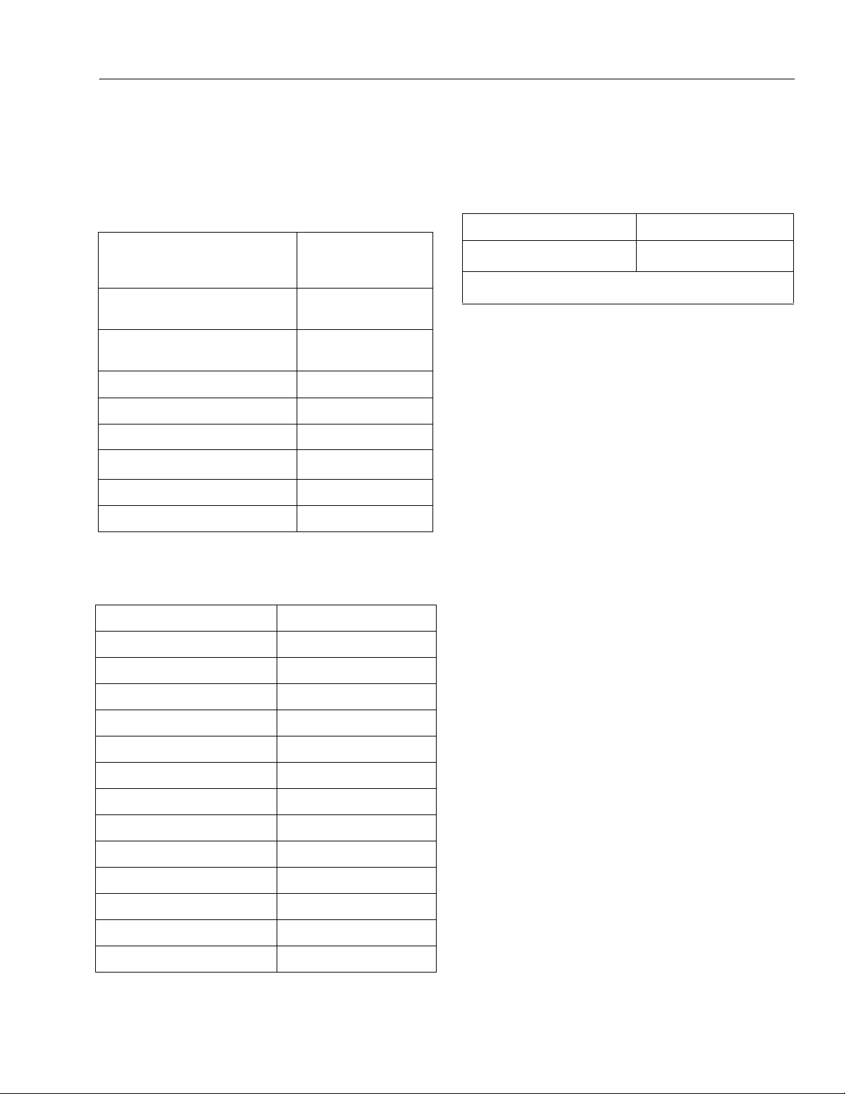
Table 1-1. Operating Specifications
Capacit y: Unres tricte d:
AN S I
AN S I E x po r t
Maximum Travel Grade, stowed
Position (Gradeability)
Maximum Travel Grade, stowed
Position (Side Slope)
Drive Speed - Stowed 2.8 mph (4.5 kph)
Elevated Drive Speed 0.75 mph (1.2 kph)
Gross Machine Weight - Approximate 23300 lbs. (10568 kg)
Ground Bearing Pressure 83 psi (5.83 kg/cm
System Voltage 12V DC
Maximum Main Relief Hyd. Pressure 3000 psi (207 Bar)
500 lbs. (227 kg)
500 lbs. (227 kg)
Dimensional Data
45%
Capacities
Table 1-3. Capacities
Hydraulic Oil Tank (to Full Level) 32.5 Gal. (123 L)
Drive Hub*
20.5 oz. (0.6 L)
*Drive hubs should be one half full of lubricant.
5°
2
)
Table 1-2. Dimensional Data
Turning Radius (Inside Left Turn) 12’ 9" (3.89 m)
Turning Radius (Inside Right Turn) 12’ 11" (3.93 m)
Turning Radius (Outside Left Turn) 22’ 10" (6.95 m)
Turning Radius (Outside Right Turn) 22’ 6" (6.85 m)
Machine Height (stowed) 9’ (2.76 m)
Machine Height (storage) 8’ 2" (2.5 m)
Machine Length (stowed) 38’ 8" (11.85 m)
Horizontal Reach 58’ 5" (17.8 m)
Machine Width (Normal Operation) 8’ 2" (2.49 m)
Machine Width (Shipping) 7’ 1" (2.2 m)
Wheel Base 9’ 6" (2.9 m)
Platform Height 80’ 5" (24.5 m)
Platform Height w/LSS 80’ 6" (24.5 m)
Ground Clearance 11.2" (28.5 cm)
3121287 – JLG Lift – 1-1
Page 14
SECTION 1 - SPECIFICATIONS
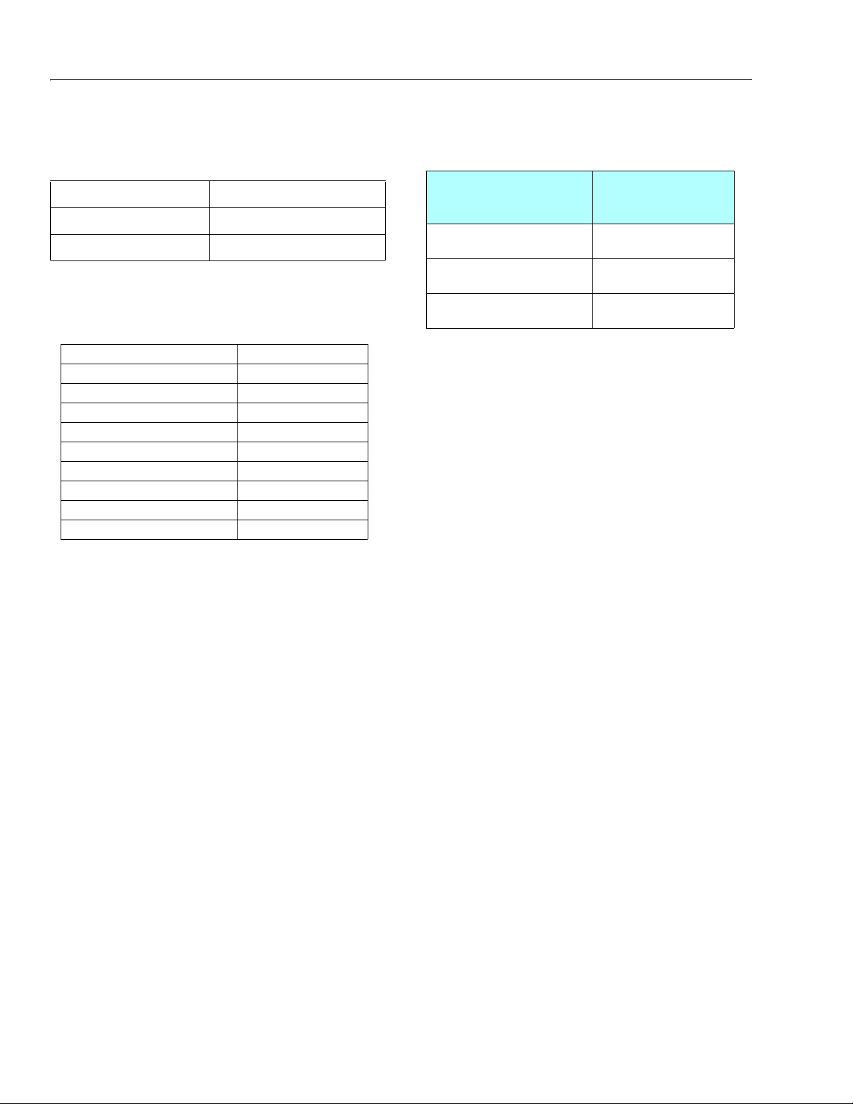
Table 1-5. Deutz D2011
Type Liquid Cooled
Number of Cylinders 4
Bore 3.7in. (94 mm)
Stroke 4 .4 in. (112 mm)
Total Displacement 189.6 cu. in. (3.1 L)
Compression Ratio 19.0:1
Firing Order 1-3-4-2
Output 36.4 hp (48.8 kW )
Low Idle RPM 1200 ± 50
High Idle RPM 2500 ± 50
Table 1-6. Hydraulic Oil
Hydraulic System
Operating
Temperature Range
S.A.E. Viscosity
Grade
+0° to + 180° F
(-18° to +83° C)
10W
+0° to + 210° F
(-18° to +99° C)
10W-20, 10W30
+50° to + 210° F
(+10° to +99° C
20W-20
Tires
Table 1-4. Tires
Size 39 x 15-22.5
Maximum Tire Load 13,100 lbs. (5942 kg)
Type Foam Fill ed
Engine Data
Hydraulic Oil
NOTE: Hydraulic oils require anti-wear qualities at least API Ser-
vice Classification GL-3, and sufficient chemical stability
for mobile hydraulic system service.
NOTE: Machines may be equipped with Mobil EAL biodegrad-
able and non-toxic hydraulic oil. This is a fully synthetic
hydraulic oil that possesses the same anti-wear and rust
protection characteristics as mineral oils, but will not
adversely affect the ground water or the environment
when spilled or leaked in small amounts.
NOTE: Aside from JLG recommendations, it is not advisable to
mix oils of different brands or types, as they may not contain the same required additives or be of comparable viscosities. If use of hydraulic oil other than Mobil 424 is
desired, contact JLG Industries for proper recommendations.
1-2 – JLG Lift – 3121287
Page 15

SECTION 1 - SPECIFICATIONS
Major Component Weights
DO NOT REPLACE ITEMS CRITICAL TO STABILITY WITH ITEMS OF DIFFERENT
WEIGHT OR SPECIFICATION (FOR EXAMPLE: BATTERIES, FILLED TIRES, PLATFORM) DO NOT MODIFY UNIT IN ANY WAY TO AFFECT STABILITY.
Table 1-7. Critical Stability Weights
Components LBS. KG.
Tire & Wheel (Foam-Filled) 513 233
Engine Assembly (w/tray) 1125 510
Battery 41 18.5
Chassis complete (w/swing bearing) 4950 2245
Chassis & Turntable (w/o booms) 11735 5323
Left Counterweights 907 411.5
Right Counterweights 907 411.5
Tower Boom 2013 913
Tower Link 893 405
1.2 FUNCTION SPEEDS
Notes:
1. Personality settings can be adjusted anywhere within
the adjustment range in order to achieve optimum
machine performance.
2. Stop watch should be started with the function movement, not with actuation of the joystick or switch.
3. All speed tests are run from the platform, except those
specifically designated to be run in Ground Mode.
4. The platform speed control knob must be at full speed
(turned clockwise completely) unless noted.
5. Functional speeds may vary due to cold thick hydraulic
oil. Test should be run with the oil temperature above
38° C (100° F)
6. Drive test results reflect 39 x 15 - 22.5 Foam Filled Tires.
Upright 1715 778
Main Boom Assembly 3475 1576
Platform 224 102
Platform Support 68 31
Platform Rotator 55 25
3121287 – JLG Lift – 1-3
Page 16

SECTION 1 - SPECIFICATIONS
Table 1-8. Machine Orientation When Performing Speed Test
Drive;
(Max Speed)
Drive;
(Max Torque)
(Above Horizo ntal)
Swing Boom at full elevation, Telescope retracted. Swing the turntable left or right to the end stop.
Main Lift Main Lift retracted, Telescope Retracted.
Telescope Main Lift completely extended, Telescope Retracted.
Platform
Rotate
Tes t s ho u ld b e d o ne o n a s mo o th , l ev el s u rf a ce . St a r t a p p ro xi m at el y 7 .6 m (2 5 ft ) fr o m s t ar t i ng p oi n t s o t he u ni t is a t a m ax i mum speed when
starting the test.
Results should be recorded for a 61m (200ft) course.
Drive forward, "High Speed", record time
Drive Reverse, "High Speed", record time
Test should be done on a smooth, level surface. The Drive Select Switch should be in the "Max Speed" position, the boom should be > 10° above
horizontal to ensure the drive is operating in Max Torque mode.
Results should be recorded for a 15.25m (50ft) course.
Drive forward, record time
Drive Re verse, record time
Turn Platform Speed Control Knob fully counterclockwise to enter Creep mode; Creep light on Panel must be energized. Verify that machine will
drive forward and reverse. Return Knob to fully clockwise.
Swing in the opposite direction until the turn table stops, record time.
Swing in the other direction until the turn table stops, record time.
Turn Platform Speed Control Knob fully counterclockwise to enter Creep mode; Creep light on Panel must be energized. Verify that machine will
swing left and right. Return Knob to fully clockwise.
Ma i n L i ft u p to f ul l he i gh t, r ec o rd ti m e.
Ma i n L i ft D o wn to s to w ed p os i ti o n, r ec o rd ti m e.
Turn Platform Speed Control Knob fully counterclockwise to enter Creep mode; Creep light on Panel must be energized. Verify that machine will
li f t u p an d d ow n. R e tu r n K n ob t o f u ll y cl o ck w is e .
Telescope out (full height), record time.
Telescope in (stowed position), record time.
Turn Platform Speed Control Knob fully counterclockwise to enter Creep mode; Creep light on Panel must be energized. Verify that machine will
telescope in and out. Return Knob to fully clockwise.
Main Lift retracted, Telescope Retracted. Rotate the platform left or right until the platform stops
Rotate the platform in the opposite direction until the platform stops, record time.
Rotate the platform in the other direction until the platform stops, record time.
Turn Platform Speed Control Knob fully counterclockwise to enter Creep mode; Creep light on Panel must be energized. Verify that machine platfo r m w i ll r ot a te le f t an d ri g ht .
Note: When the platform speed control knob is turned fully counterclockwise. The platform rotate may not work, this is acceptable. Return Knob
to fully clockw ise.
1-4 – JLG Lift – 3121287
Page 17
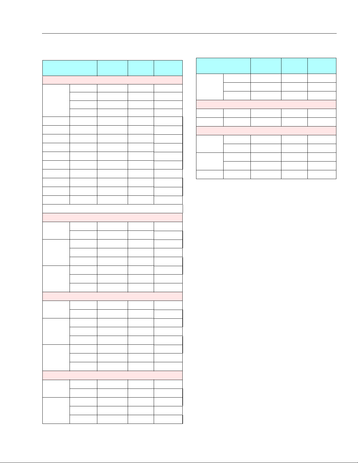
SECTION 1 - SPECIFICATIONS
Table 1-9. Function Speeds
Function
Adjustment
Ranges
Default
Setting
Time Range
In Seconds
DRIVE
Max Speed Accel 25 – 2000mA/s 275 mA
Decel 25 – 2000mA/s 175 mA
Min 250 – 1800mA 635 mA
Max 250 – 1800mA 1650 mA 48-52
ME/ MT Accel 25 – 2000mA/s 300 mA
ME/ MT Decel 25 – 2000mA/s 100 mA
Drive to Stop Decel 25 – 2000mA/s 1075 mA
ME/ MT: Min 250 – 1800mA 625 mA
Max Torque Max 250 – 1800mA 1650 mA
Mid Engine Max 250 – 1800mA 1650 mA
MT: Elevated Max 250 – 1400mA 1150 mA 44 - 57
ME: Elevated Max 250 – 1400mA 1200 mA
Max Torque Creep 250 – 1400mA 1125 mA
Mid Engine Creep 250 – 1400mA 1200 mA
ME = Max Engine, MT = Max Touque
SWING
Accel 0-5s 2.5 s
Decel 0-5s 1 s
LEFT Min 250 – 1400mA 500 mA
Max 250 – 1400mA 700 mA 109 - 132
Creep 250 – 1400mA 550 mA
RIGHT Min 250 – 1400mA 475 mA
Max 250 – 1400mA 700 mA 109 - 132
Creep 250 – 1400mA 520 mA
LIFT
Accel 0-5s 2 s
Decel 0-5s 1 s
UP Min 250 – 1400mA 400 mA
Max 250 – 1400mA 925 mA 62 - 76
Creep 250 – 1400mA 600 mA
DOWN Min 250 – 1400mA 400 mA
Max 250 – 1400mA 1025 mA 52 - 64
Creep 250 – 1400mA 825 mA
TELECOPE
Accel 0-5s 2 s
Decel 0-5s 0.3 s
IN Min 250 – 1400mA 400 mA
Max 250 – 1400mA 925 mA 47 - 58
Creep 250 – 1400mA 700 mA
Table 1-9. Function Speeds
Function
Adjustment
Ranges
Default
Setting
Time Range
In Seconds
OUT Min 250 – 1400mA 400 mA
Max 250 – 1400mA 1100 mA 55 - 67
Creep 250 – 1400mA 675 mA
PLATFORM ROTATE
LEFT Max No Adjustment N/A 17-35
RIGHT Max No Adjustment N/A 17-35
GROUND MODE
SWING Left 250 – 1400mA 625 mA N/A
Right 250 – 1400mA 625 mA N/A
LIFT Up 250 – 1400mA 825 mA N/A
Down 250 – 1400mA 1025 mA N/A
TELESCOPE In/Out 250 – 1400mA 1000 mA N/A
1001147535-C
3121287 – JLG Lift – 1-5
Page 18
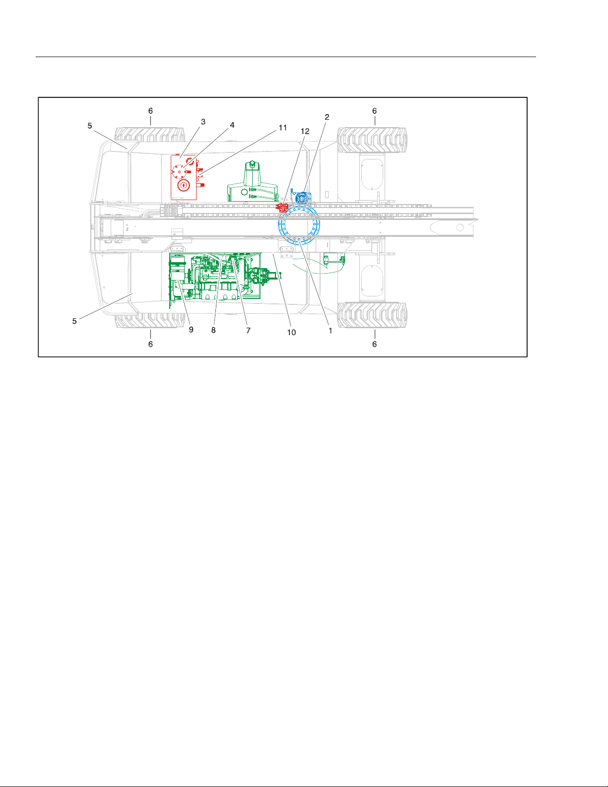
SECTION 1 - SPECIFICATIONS
Figure 1-1. Maintenance and Lubrication Diagram
1-6 – JLG Lift – 3121287
Page 19
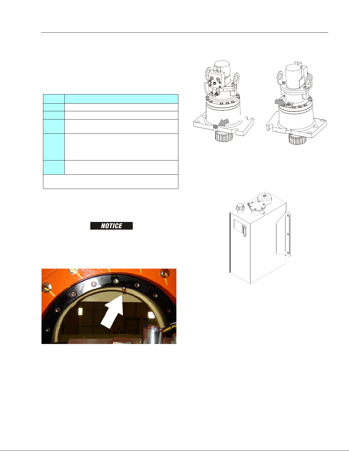
SECTION 1 - SPECIFICATIONS
Table 1-10. Lubrication Specifications.
KEY SPECIFICATIONS
BG* Bearing Grease (JLG Part No. 3020029) Mobilith SHC 460.
HO Hydraulic Oil. API service classification GL-4, e.g. Mobilfluid 424.
EPGL Extreme Pressure Gear Lube (oil) meeting API Service Classification GL-5
or Mil-Spec Mil-L-2105.
MPG Multipurpose Grease having a minimum dripping point of 350° F (177°
C). Excellent water resistance and adhesive qualities, and being of
extreme pressure type.
(Timken OK 40 pounds minimum.)
EO Engine (crankcase) Oil. Gas - API SF, SH, SG class, MIL-L-2104. Diesel - API
CC/CD class, MIL-L-2104B/MIL-L-2104C.
*MPG may be substituted for these lub ricants, if necessary, but service intervals will be
reduced.
DRAIN
FILL
1.1 OPERATOR MAINTENANCE
NOTE: The following numbers correspond to those in Figure 1-1.,
Maintenance and Lubrication Diagram.
2. Swing Gearbox
Lube Point(s) - Fill Plug
Capacity - 32 ounces (946 cc)
Lube - EPGL
Interval - Check level every 150 hrs/Change every 1200
hours of operation. Fill to cover ring gear.
3. Hydraulic Tank
LUBRICATION INTERVALS ARE BASED ON MACHINE OPERATION UNDER NORMAL CONDITIONS. FOR MACHINES USED IN MULTI-SHIFT OPERATIONS AND/
OR EXPOSED TO HOSTILE ENVIRONMENTS OR CONDITIONS, LUBRICATION
FREQUENCIES MUST BE INCREASED ACCORDINGLY.
1. Swing Bearing
Lube Point(s) - 2 Fittings
Capacity - A/R
Lube - BG
Interval - Every 3 months or 150 hrs of operation
Comments - Apply grease and rotate in 90 degree
intervals until bearing is completely lubricated
3121287 – JLG Lift – 1-7
Lube Point(s) - Fill Cap
Capacity - 36 Gal. (136.3 L), 32.5 Gal. (123 L) to Full Level;
26.5 Gal (100.3 L) to Refill Mark
Lube - HO
Interval - Check Level daily; Change every 2 years or
1200 hours of operation.
Comments - On new machines, those recently over-
hauled, or after changing hydraulic oil, operate all systems a minimum of two complete cycles and recheck
oil level in reservoir.
Page 20
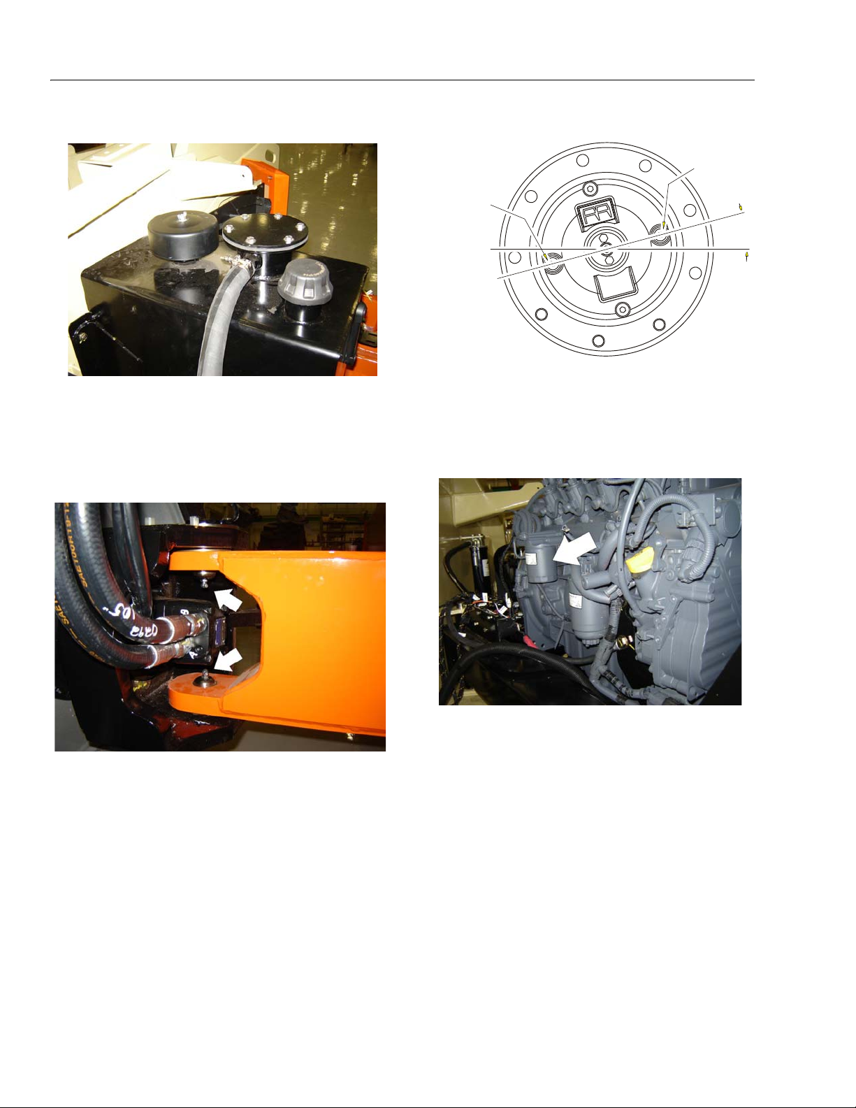
SECTION 1 - SPECIFICATIONS
FILL PORT
15°
OIL SHOULD BE
TO THIS HEIGHT
4. Hydraulic Tank Return Filter and Breather
Interval - Change after first 50 hrs. and every 6 months
or 300 hrs. thereafter.
Comments - For breather element, remove wing nut and
cover to replace. Under certain conditions, it may be
necessary to replace both elements on a more frequent basis.
5. King Pins
6. Wheel Drive Hub
Lube Point(s) - Level/Fill Plug
Capacity - 20.5 oz. (0.6 L)
Lube - Mineral Oil ISO VG150
Interval - Check level every 3 months or 150 hrs of operation; change every 2 years or 1200 hours of operation
7. Oil Change with Filter
1-8 – JLG Lift – 3121287
Lube Point(s) - 2 Grease Fittings
Capacity - As Required
Lube - MPG
Interval - Every 3 months or 150 hrs of operation
Lube Point(s) - Fill Cap/Spin-on Element
Total Capacity (Engine & Oil Cooler)- 15 Quarts (14.2 L)
w/Filter
Lube - EO
Interval - Check level daily; change every 600 hours or
six months, whichever comes first. Adjust final oil
level by mark on dipstick.
Page 21
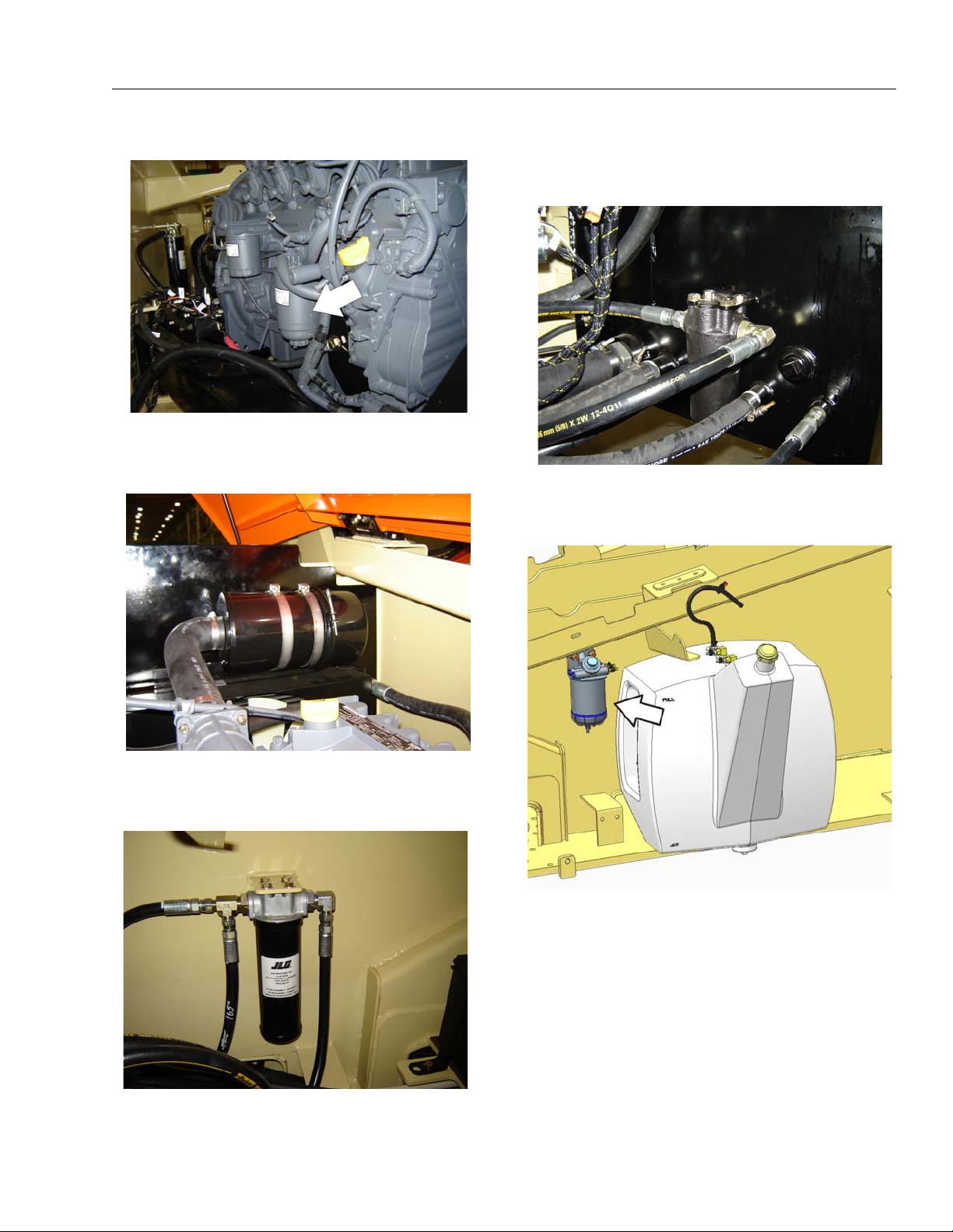
SECTION 1 - SPECIFICATIONS
8. Fuel Filter/Water Separator
Lube Point(s) - Replaceable Element
Interval - Every year or 600 hours of operation
9. Air Filter
Interval - Change after first 50 hrs. and every 6 months
or 300 hrs. thereafter.
11. Main Valve Filter
Interval - Change after first 50 hrs. and every 6 months
or 300 hrs. thereafter.
12. Optional Fuel Filter
Lube Point(s) - Replaceable Element
Interval - Every 6 months or 300 hours of operation
10. Charge Filter
Lube Point(s) - Replaceable Element
Interval - Every year or 600 hours of operation
3121287 – JLG Lift – 1-9
Page 22
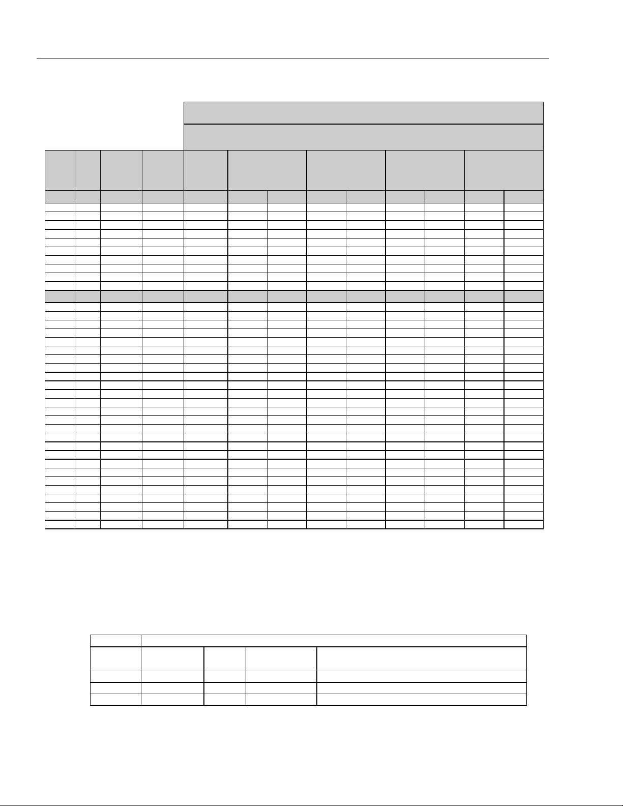
SECTION 1 - SPECIFICATIONS
REFERENCE JLG ANEROBIC THREAD LOCKING COMPOUND
JLG P/N Loctite® P/N ND Industries P/N
Description
0100011
242
TM
Vibra-TITE
TM
121
Medium Strength (Blue)
0100019
271
TM
Vibra-TITE
TM
140
High Strength (Red)
0100071
262
TM
Vibra-TITE
TM
131
Medium - High Strength (Red)
Size TPI Bolt Dia
Tensile
Stress Area
Clamp Load
In Sq In LB IN-LB [N.m] IN-LB [N.m] IN-LB [N.m] IN-LB [N.m]
4 40 0.1120 0.00604 380 8 0.9 6 0.7
48 0.1120 0.00661 420 9 1.0 7 0.8
6 32 0.1380 0.00909 580 16 1.8 12 1.4
40 0.1380 0.01015 610 18 2.0 13 1.5
8 32 0.1640 0.01400 900 30 3.4 22 2.5
36 0.1640 0.01474 940 31 3.5 23 2.6
10 24 0.1900 0.01750 1120 43 4.8 32 3.5
32 0.1900 0.02000 1285 49 5.5 36 4
1/4 20 0.2500 0.0318 2020 96 10.8 75 9 105 12
28 0.2500 0.0364 2320 120 13.5 86 10 135 15
In Sq In LB FT-LB [N.m] FT-LB [N.m] FT-LB [N.m] FT-LB [N.m]
5/16 18 0.3125 0.0524 3340 17 23 13 18 19 26 16 22
24 0.3125 0.0580 3700 19 26 14 19 21 29 17 23
3/8 16 0.3750 0.0775 4940 30 41 23 31 35 48 28 38
24 0.3750 0.0878 5600 35 47 25 34 40 54 32 43
7/16 14 0.4375 0.1063 6800 50 68 35 47 55 75 45 61
20 0.4375 0.1187 7550 55 75 40 54 60 82 50 68
1/2 13 0.5000 0.1419 9050 75 102 55 75 85 116 68 92
20 0.5000 0.1599 10700 90 122 65 88 100 136 80 108
9/16 12 0.5625 0.1820 11600 110 149 80 108 120 163 98 133
18 0.5625 0.2030 12950 120 163 90 122 135 184 109 148
5/8 11 0.6250 0.2260 14400 150 203 110 149 165 224 135 183
18 0.6250 0.2560 16300 170 230 130 176 190 258 153 207
3/4 10 0.7500 0.3340 21300 260 353 200 271 285 388 240 325
16 0.7500 0.3730 23800 300 407 220 298 330 449 268 363
7/8 9 0.8750 0.4620 29400 430 583 320 434 475 646 386 523
14 0.8750 0.5090 32400 470 637 350 475 520 707 425 576
1 8 1.0000 0.6060 38600 640 868 480 651 675 918 579 785
12 1.0000 0.6630 42200 700 949 530 719 735 1000 633 858
1 1/8 7 1.1250 0.7630 42300 800 1085 600 813 840 1142 714 968
12 1.1250 0.8560 47500 880 1193 660 895 925 1258 802 1087
1 1/4 7 1.2500 0.9690 53800 1120 1518 840 1139 1175 1598 1009 1368
12 1.2500 1.0730 59600 1240 1681 920 1247 1300 1768 1118 1516
1 3/8 6 1.3750 1.1550 64100 1460 1979 1100 1491 1525 2074 1322 1792
12 1.3750 1.3150 73000 1680 2278 1260 1708 1750 2380 1506 2042
1 1/2 6 1.5000 1.4050 78000 1940 2630 1460 1979 2025 2754 1755 2379
12 1.5000 1.5800 87700 2200 2983 1640 2224 2300 3128 1974 2676
NO. 5000059 REV. J
Values for Zinc Yellow Chromate Fasteners (Ref 4150707)
SAE GRADE 5 BOLTS & GRADE 2 NUTS
Torque
(Dry)
Torque
(Loctite® 262
TM
or Vibra-
TITE
TM
131)
Torque
Lubricated
Torque
(Loctite® 242
TM
or 271
TM
OR Vibra-TIT E
TM
111 or
140)
3. * ASSEMBLY USES HARDENED WASHER
NOTES: 1. THESE TORQUE VALUES DO NOT APPLY TO CADMIUM PLATED FASTENERS
2. ALL TORQUE VALUES ARE STATIC TORQUE MEASURED PER STANDARD AUDIT METHODS TOLERANCE = ±10%
Figure 1-2. Torque Chart (SAE Fasteners - Sheet 1 of 7)
1-10 – JLG Lift – 3121287
Page 23
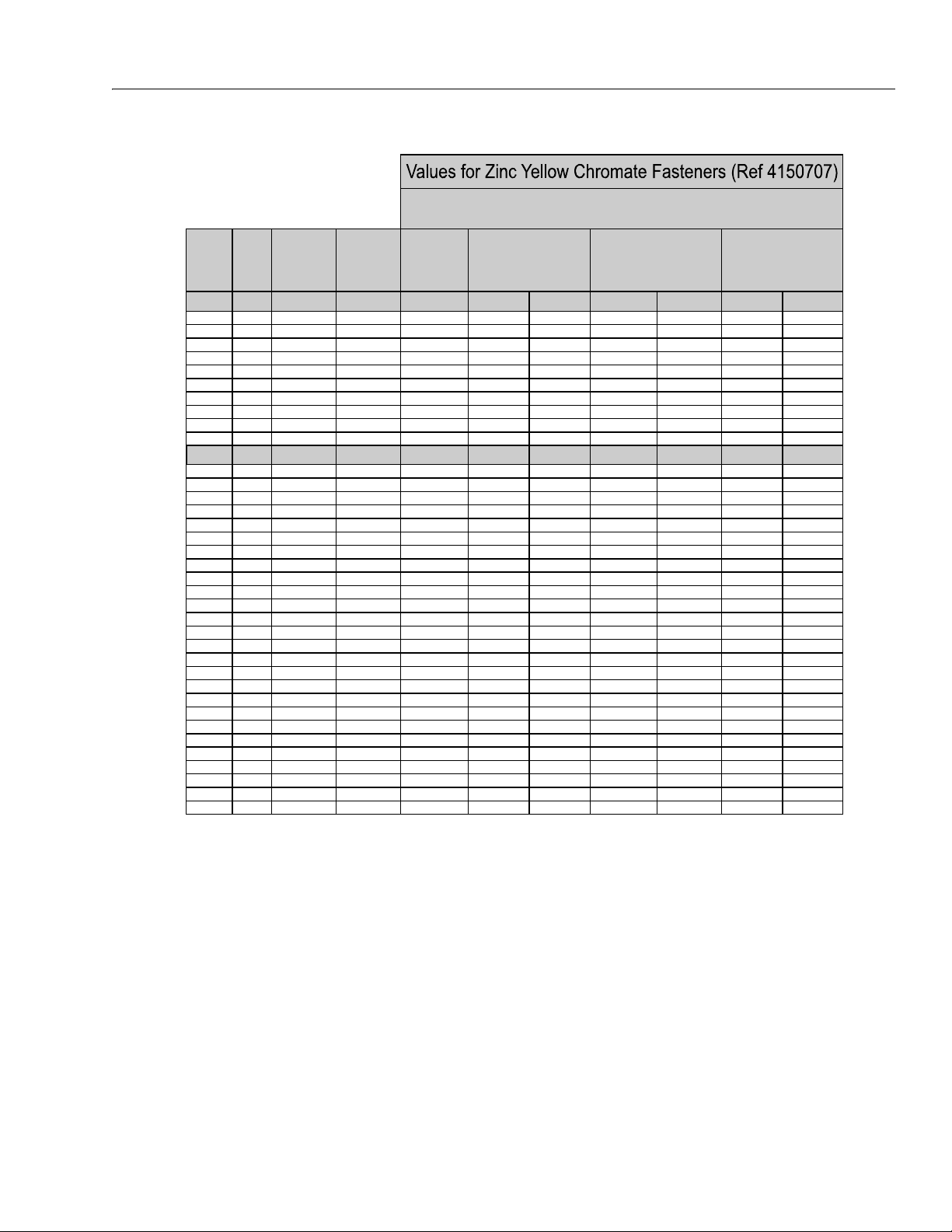
SECTION 1 - SPECIFICATIONS
Size TPI Bolt Dia
Tensile
Stress Area
Clamp Load
In Sq In
4 40 0.1120 0.00604
48 0.1120 0.00661
6 32 0.1380 0.00909
40 0.1380 0.01015
8 32 0.1640 0.01400
36 0.1640 0.01474
10 24 0.1900 0.01750
32 0.1900 0.02000
1/4 20 0.2500 0.0318
28 0.2500 0.0364
In Sq In
5/16 18 0.3125 0.0524
24 0.3125 0.0580
3/8 16 0.3750 0.0775
24 0.3750 0.0878
7/16 14 0.4375 0.1063
20 0.4375 0.1187
1/2 13 0.5000 0.1419
20 0.5000 0.1599
9/16 12 0.5625 0.1820
18 0.5625 0.2030
5/8 11 0.6250 0.2260
18 0.6250 0.2560
3/4 10 0.7500 0.3340
16 0.7500 0.3730
7/8 9 0.8750 0.4620
14 0.8750 0.5090
1 8 1.0000 0.6060
12 1.0000 0.6630
1 1/8 7 1.1250 0.7630
12 1.1250 0.8560
1 1/4 7 1.2500 0.9690
12 1.2500 1.0730
1 3/8 6 1.3750 1.1550
12 1.3750 1.3150
1 1/2 6 1.5000 1.4050
12 1.5000 1.5800
NO. 5000059 REV. J
3. * ASSEMBLY USES HARDENED WASHER
NOTES: 1. THESE TORQUE VALUES DO NOT APPLY TO CADMIUM PLATED FASTENERS
2. ALL TORQUE VALUES ARE STATIC TORQUE MEASURED PER STANDARD AUDIT METHODS TOLERANCE = ±10%
LB IN-LB [N.m] IN-LB [N.m] IN-LB [N.m]
1320 43 5
1580 60 7
1800 68 8
2860 143 16 129 15
3280 164 19 148 17
LB FT-LB [N.m] FT-LB [N.m] FT-LB [N.m
4720 25 35 20 25 20 25
5220 25 35 25 35 20 25
7000456040 553550
7900 50 70 45 60 35 50
9550 70 95 65 90 50 70
10700 80 110 70 95 60 80
12750 105 145 95 130 80 110
14400 120 165 110 150 90 120
16400 155 210 140 190 115 155
18250 170 230 155 210 130 175
20350 210 285 190 260 160 220
23000 240 325 215 290 180 245
30100 375 510 340 460 280 380
33600 420 570 380 515 315 430
41600 605 825 545 740 455 620
45800 670 910 600 815 500 680
51500 860 1170 770 1045 645 875
59700 995 1355 895 1215 745 1015
68700 1290 1755 1160 1580 965 1310
77000 1445 1965 1300 1770 1085 1475
87200 1815 2470 1635 2225 1365 1855
96600 2015 2740 1810 2460 1510 2055
104000 2385 3245 2145 2915 1785 2430
118100 2705 3680 2435 3310 2030 2760
126500 3165 4305 2845 3870 2370 3225
142200 3555 4835 3200 4350 2665 3625
Torque
(Loctite® 242
TM
or 271
TM
OR Vibra-TITE
TM
111 or
140) K=.18
Torque
(Loctite® 262
TM
or Vibra-
TITE
TM
131)
K=0.15
SAE GRADE 8 (HEX HD) BOLTS & GRADE 8 NUTS*
Torque
(Dry or Loctite® 263)
K= 0.20
3121287 – JLG Lift – 1-11
Figure 1-3. Torque Chart (SAE Fasteners - Sheet 2 of 7)
Page 24
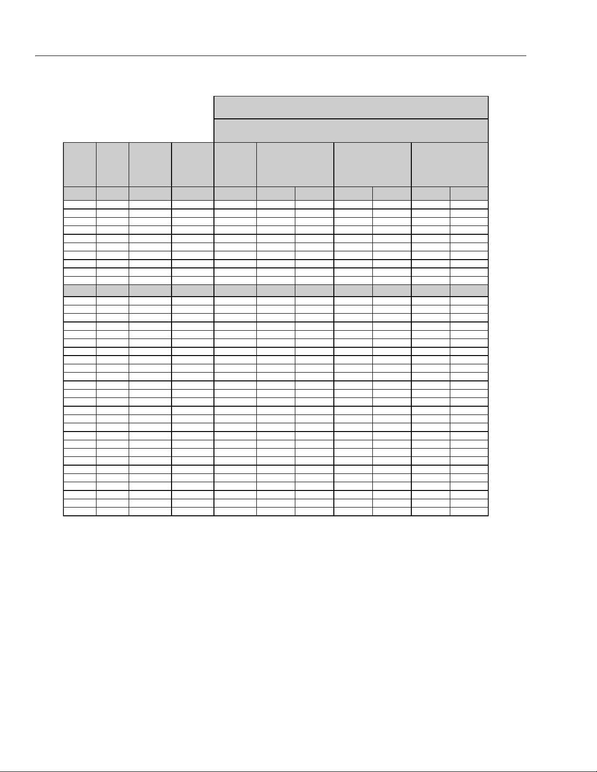
SECTION 1 - SPECIFICATIONS
Size TPI Bolt Dia
Tensile
Stress Area
Clamp Load
See Note 4
In Sq In LB IN-LB [N.m] IN-LB [N.m] IN-LB [N.m]
4 40 0.1120 0.00604
48 0.1120 0.00661
6 32 0.1380 0.00909
40 0.1380 0.01015
8 32 0.1640 0.01400
36 0.1640 0.01474
10 24 0.1900 0.01750
32 0.1900 0.02000
1/4 20 0.2500 0.0318 2860 122 14 114 13
28 0.2500 0.0364 3280 139 16 131 15
In Sq In LB FT-LB [N.m] FT-LB [N.m] FT-LB [N.m]
5/16 18 0.3125 0.0524 4720 20 25 20 25 20 25
24 0.3125 0.0580 5220 25 35 20 25 20 25
3/8 16 0.3750 0.0775 7000 35 50 35 50 35 50
24 0.3750 0.0878 7900 40 55 40 55 35 50
7/16 14 0.4375 0.1063 9550 60 80 55 75 50 70
20 0.4375 0.1187 10700 65 90 60 80 60 80
1/2 13 0.5000 0.1419 12750 90 120 85 115 80 110
20 0.5000 0.1599 14400 100 135 95 130 90 120
9/16 12 0.5625 0.1820 16400 130 175 125 170 115 155
18 0.5625 0.2030 18250 145 195 135 185 130 175
5/8 11 0.6250 0.2260 20350 180 245 170 230 160 220
18 0.6250 0.2560 23000 205 280 190 260 180 245
3/4 10 0.7500 0.3340 30100 320 435 300 410 280 380
16 0.7500 0.3730 33600 355 485 335 455 315 430
7/8 9 0.8750 0.4620 41600 515 700 485 660 455 620
14 0.8750 0.5090 45800 570 775 535 730 500 680
1 8 1.0000 0.6060 51500 730 995 685 930 645 875
12 1.0000 0.6630 59700 845 1150 795 1080 745 1015
1 1/8 7 1.1250 0.7630 68700 1095 1490 1030 1400 965 1310
12 1.1250 0.8560 77000 1225 1665 1155 1570 1085 1475
1 1/4 7 1.2500 0.9690 87200 1545 2100 1455 1980 1365 1855
12 1.2500 1.0730 96600 1710 2325 1610 2190 1510 2055
1 3/8 6 1.3750 1.1550 104000 2025 2755 1905 2590 1785 2430
12 1.3750 1.3150 118100 2300 3130 2165 2945 2030 2760
1 1/2 6 1.5000 1.4050 126500 2690 3660 2530 3440 2370 3225
12 1.5000 1.5800 142200 3020 4105 2845 3870 2665 3625
NO. 5000059 REV. J
4. CLAMP LOAD LISTED FOR SHCS IS SAME AS GRADE 8 OR CLASS 10.9 AND DOES NOT REPRESENT FULL STRENGTH
CAPABILITY OF SHCS. IF HIGHER LOAD IS REQUIRED, ADDITIONAL TESTING IS REQUIRED.
SOCKET HEAD CAP SCREWS
Magni Coating (Ref 4150701)*
Torque
(Dry) K = .17
Torque
(Loctite® 242
TM
or 271
TM
OR Vibra-TITE
TM
111 or
140 OR Precoat 85®
K=0.16
Torque
(Loctite® 262
TM
or Vibra-
TITE
TM
131)
K=0.15
2. ALL TORQUE VALUES ARE STATIC TORQUE MEASURED PER STANDARD AUDIT METHODS TOLERANCE = ±10%
NOTES: 1. THESE TORQUE VALUES DO NOT APPLY TO CADMIUM PLATED FASTENERS
*3. ASSEMBLY USES HARDENED WASHER OR FASTENER IS PLACED AGAINST PLATED STEEL OR RAW ALUMINUM
1-12 – JLG Lift – 3121287
Figure 1-4. Torque Chart (SAE Fasteners - Sheet 3 of 7)
Page 25

Size TPI Bolt Dia
Tensile
Stress Area
Clamp Load
See Note 4
In Sq In LB IN-LB [N.m] IN-LB [N.m] IN-LB [N.m]
4 40 0.1120 0.00604
48 0.1120 0.00661
6 32 0.1380 0.00909
40 0.1380 0.01015
8 32 0.1640 0.01400
36 0.1640 0.01474
10 24 0.1900 0.01750
32 0.1900 0.02000
1/4 20 0.2500 0.0318 2860 143 16 129 15
28 0.2500 0.0364 3280 164 19 148 17
In Sq In LB FT-LB [N.m] FT-LB [N.m] FT-LB [N.m]
5/16 18 0.3125 0.0524 4720 25 35 20 25 20 25
24 0.3125 0.0580 5220 25 35 25 35 20 25
3/8 16 0.3750 0.0775 7000 45 60 40 55 35 50
24 0.3750 0.0878 7900 50 70 45 60 35 50
7/16 14 0.4375 0.1063 9550 70 95 65 90 50 70
20 0.4375 0.1187 10700 80 110 70 95 60 80
1/2 13 0.5000 0.1419 12750 105 145 95 130 80 110
20 0.5000 0.1599 14400 120 165 110 150 90 120
9/16 12 0.5625 0.1820 16400 155 210 140 190 115 155
18 0.5625 0.2030 18250 170 230 155 210 130 175
5/8 11 0.6250 0.2260 20350 210 285 190 260 160 220
18 0.6250 0.2560 23000 240 325 215 290 180 245
3/4 10 0.7500 0.3340 30100 375 510 340 460 280 380
16 0.7500 0.3730 33600 420 570 380 515 315 430
7/8 9 0.8750 0.4620 41600 605 825 545 740 455 620
14 0.8750 0.5090 45800 670 910 600 815 500 680
1 8 1.0000 0.6060 51500 860 1170 775 1055 645 875
12 1.0000 0.6630 59700 995 1355 895 1215 745 1015
1 1/8 7 1.1250 0.7630 68700 1290 1755 1160 1580 965 1310
12 1.1250 0.8560 77000 1445 1965 1300 1770 1085 1475
1 1/4 7 1.2500 0.9690 87200 1815 2470 1635 2225 1365 1855
12 1.2500 1.0730 96600 2015 2740 1810 2460 1510 2055
1 3/8 6 1.3750 1.1550 104000 2385 3245 2145 2915 1785 2430
12 1.3750 1.3150 118100 2705 3680 2435 3310 2030 2760
1 1/2 6 1.5000 1.4050 126500 3165 4305 2845 3870 2370 3225
12 1.5000 1.5800 142200 3555 4835 3200 4350 2665 3625
NO. 5000059 REV. J
4. CLAMP LOAD LISTED FOR SHCS IS SAME AS GRADE 8 OR CLASS 10.9 AND DOES NOT REPRESENT FULL STRENGTH
CAPABILITY OF SHCS. IF HIGHER LOAD IS REQUIRED, ADDITIONAL TESTING IS REQUIRED.
SOCKET HEAD CAP SCREWS
Torque
(Dry)
K = .20
Torque
(Loctite® 242TM or 271
TM
OR Vibra-TITE
TM
111 or
140 OR Precoat 85®
K=0.18
Zinc Yellow Chromate Fasteners (Ref 4150707)*
2. ALL TORQUE VALUES ARE STATIC TORQUE MEASURED PER STANDARD AUDIT METHODS TOLERANCE = ±10%
NOTES: 1. THESE TORQUE VALUES DO NOT APPLY TO CADMIUM PLATED FASTENERS
*3. ASSEMBLY USES HARDENED WASHER OR FASTENER IS PLACED AGAINST PLATED STEEL OR RAW ALUMINUM
Torque
(Loctite® 262
TM
or Vibra-
TITE
TM
131)
K=0.15
SECTION 1 - SPECIFICATIONS
3121287 – JLG Lift – 1-13
Figure 1-5. Torque Chart (SAE Fasteners - Sheet 4 of 7)
Page 26
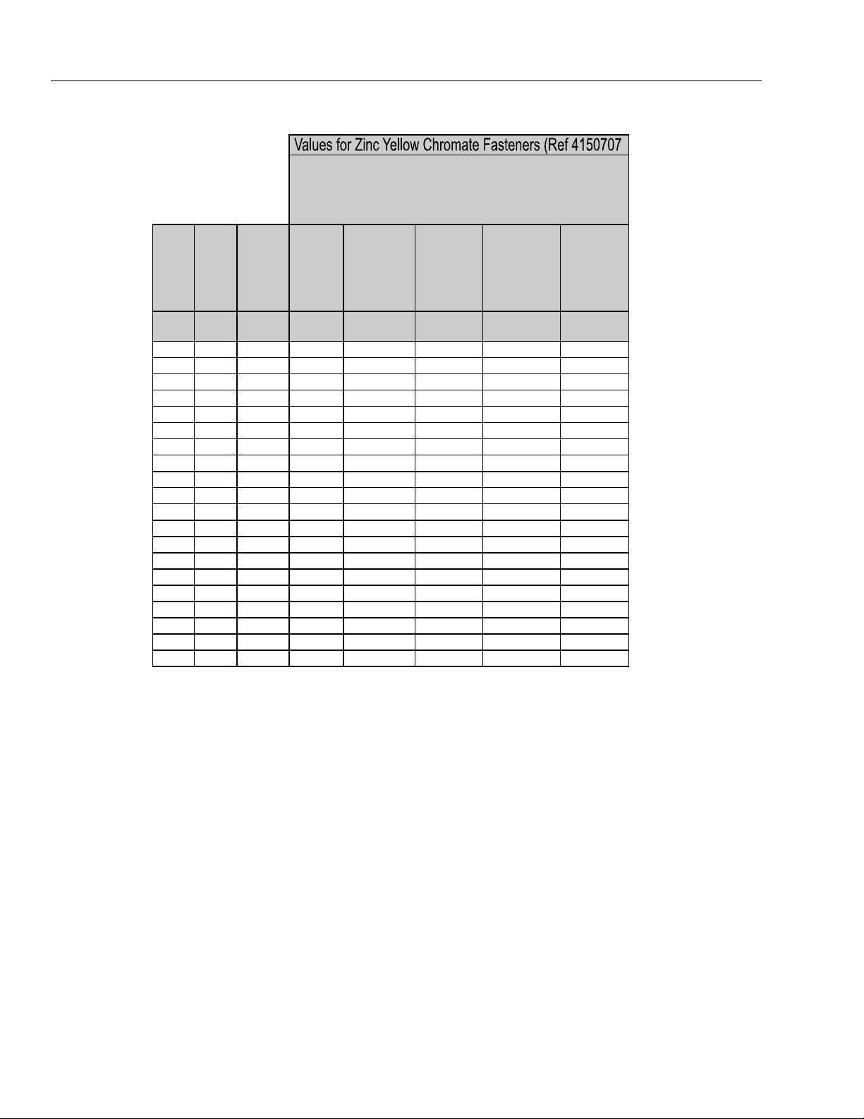
SECTION 1 - SPECIFICATIONS
Size PITCH
Tensile
Stress
Area
Clamp
Load
Torque
(Dry or Loctite®
263
TM
)
Torque
(Lub)
Torque
(Loctite® 262
TM
OR Vibra-
TITE
TM
131)
Torque
(Loctite®
242
TM
or 271
TM
OR Vibra-
TITE
TM
111 or
140)
Sq mm KN [N.m] [N.m] [N.m] [N.m]
3 0.5 5.03 2.19 1.3 1.0 1.2 1.4
3.5 0.6 6.78 2.95 2.1 1.6 1.9 2.3
4 0.7 8.78 3.82 3.1 2.3 2.8 3.4
5 0.8 14.20 6.18 6.2 4.6 5.6 6.8
6 1 20.10 8.74 11 7.9 9.4 12
7 1 28.90 12.6 18 13 16 19
8 1.25 36.60 15.9 26 19 23 28
10 1.5 58.00 25.2 50 38 45 55
12 1.75 84.30 36.7 88 66 79 97
14 2 115 50.0 140 105 126 154
16 2 157 68.3
219 164 197 241
18 2.5 192 83.5 301 226 271 331
20 2.5 245 106.5 426 320 383 469
22 2.5 303 132.0 581 436 523 639
24 3 353 153.5 737 553 663 811
27 3 459 199.5 1080 810 970 1130
30 3.5 561 244.0 1460 1100 1320 1530
33 3.5 694 302.0 1990 1490 1790 2090
36 4 817 355.5 2560 1920 2300 2690
42 4.5 1120 487.0 4090 3070 3680 4290
4. CLAMP LOAD LISTED FOR SHCS IS SAME AS GRADE 8 OR CLASS 10.9 AND DOES NOT
REPRESENT FULL STRENGTH CAPABILITY OF SHCS. IF HIGHER LOAD IS REQUIRED,
ADDITIONAL TESTING IS REQUIRED.
*3. ASSEMBLY USES HARDENED WASHER OR FASTENER IS PLACED AGAINST PLATED
STEEL OR RAW ALUMINUM
CLASS 8.8 METRIC BOLTS
CLASS 8 METRIC NUTS
NOTES: 1. THESE TORQUE VALUES DO NOT APPLY TO CADMIUM PLATED FASTENERS
2. ALL TORQUE VALUES ARE STATIC TORQUE MEASURED PER STANDARD AUDIT
METHODS TOLERANCE = ±10%
NO. 5000059 REV. J
Figure 1-6. Torque Chart (METRIC Fasteners - Sheet 5 of 7)
1-14 – JLG Lift – 3121287
Page 27
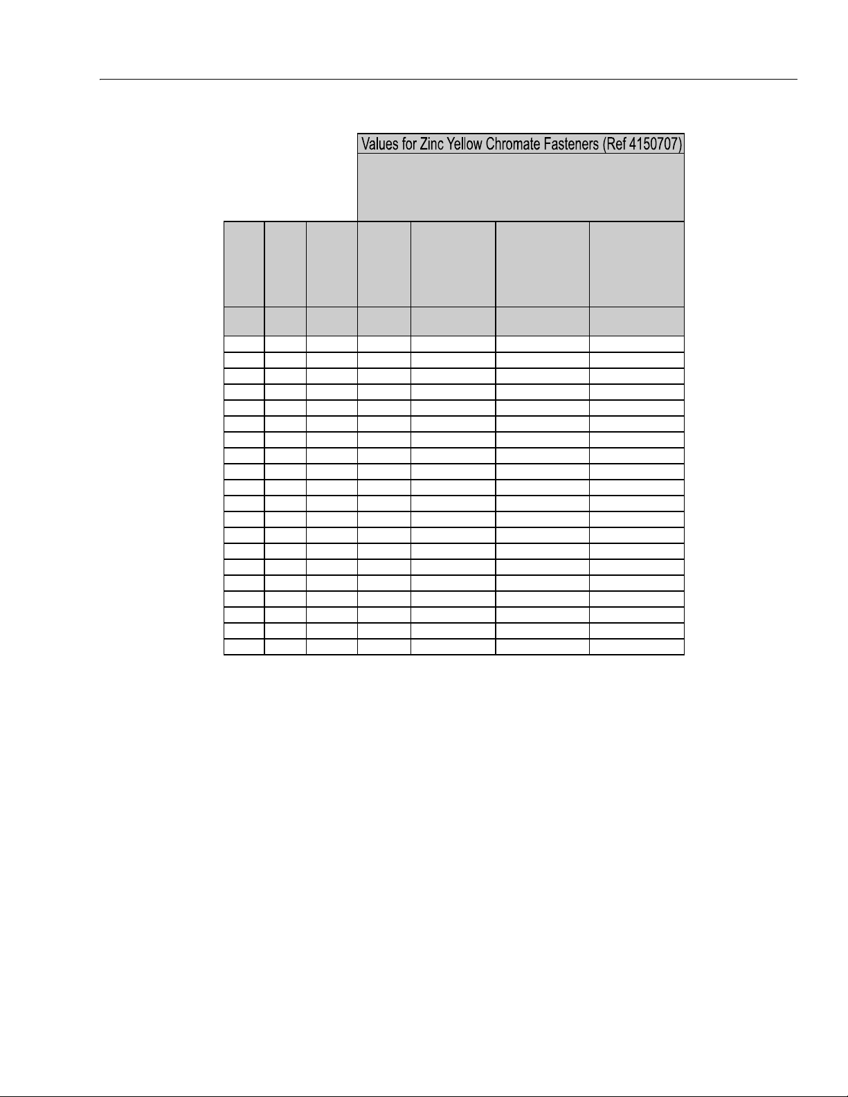
SECTION 1 - SPECIFICATIONS
Size PITCH
Tensile
Stress
Area
Clamp
Load
Torque
(Dry or Loctite®
263
TM
)
K = 0.20
Torque
(Lub OR Loctite®
242
TM
or 271TM OR
Vibra-TITE
TM
111 or
140)
K= 0.18
Torque
(Loctite® 262
TM
OR
Vibra-TITE
TM
131)
K=0.15
Sq mm KN [N.m] [N.m] [N.m]
3 0.5 5.03 3.13
3.5 0.6 6.78 4.22
4 0.7 8.78 5.47
5 0.8 14.20 8.85
6 1 20.10 12.5
7 1 28.90 18.0 25.2 22.7 18.9
8 1.25 36.60 22.8 36.5 32.8 27.4
10 1.5 58.00 36.1 70 65 55
12 1.75 84.30 52.5 125 115 95
14 2 115 71.6 200 180 150
16 2 157 97.8
315 280 235
18 2.5 192 119.5 430 385 325
20 2.5 245 152.5 610 550 460
22 2.5 303 189.0 830 750 625
24 3 353 222.0 1065 960 800
27 3 459 286.0 1545 1390 1160
30 3.5 561 349.5 2095 1885 1575
33 3.5 694 432.5 2855 2570 2140
36 4 817 509.0 3665 3300 2750
42 4.5 1120 698.0 5865 5275 4395
CLASS 10.9 METRIC BOLTS
CLASS 10 METRIC NUTS
CLASS 12.9 SOCKET HEAD CAP SCREWS M3 - M5*
4. CLAMP LOAD LISTED FOR SHCS IS SAME AS GRADE 8 OR CLASS 10.9 AND DOES NOT
REPRESENT FULL STRENGTH CAPABILITY OF SHCS. IF HIGHER LOAD IS REQUIRED,
ADDITIONAL TESTING IS REQUIRED.
*3. ASSEMBLY USES HARDENED WASHER OR FASTENER IS PLACED AGAINST PLA TED
STEEL OR RAW ALUMINUM
NOTES: 1. THESE TORQUE VALUES DO NOT APPLY TO CADMIUM PLATED FASTENERS
2. ALL TORQUE VALUES ARE STATIC TORQUE MEASURED PER STANDARD AUDIT
METHODS TOLERANCE = ±10%
NO. 5000059 REV. J
3121287 – JLG Lift – 1-15
Figure 1-7. Torque Chart (METRIC Fasteners - Sheet 6 of 7)
Page 28
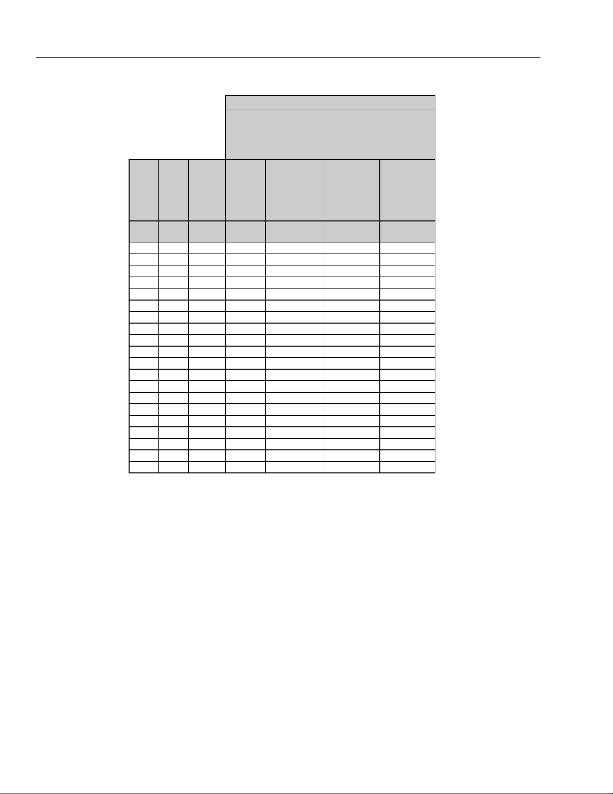
SECTION 1 - SPECIFICATIONS
Size PITCH
Tensile
Stress
Area
Clamp Load
See Note 4
Torque
(Dry or Loctite®
263
TM
)
K = .17
Torque
(Lub OR Loctite®
242
TM
or 271
TM
OR Vibra-TITE
TM
111 or 140)
K = .16
Torque
(Loctite® 262
TM
OR Vibra-TITE
TM
131)
K = .15
Sq mm kN [N.m] [N.m] [N.m]
30.55.03
3.5 0.6 6.78
40.78.78
50.814.20
6120.1012.5 13 12 11
7128.9018.0 21 20 19
8 1.25 36.60 22.8 31 29 27
10 1.5 58.00 36.1 61 58 54
12 1.75 84.30 52.5 105 100 95
14 2 115 71.6 170 160 150
16 2 157
97.8 265 250 235
18 2.5 192 119.5 365 345 325
20 2.5 245 152.5 520 490 460
22 2.5 303 189.0 705 665 625
24 3 353 220.0 900 845 790
27 3 459 286.0 1315 1235 1160
30 3.5 561 349.5 1780 1680 1575
33 3.5 694 432.5 2425 2285 2140
36 4 817 509.0 3115 2930 2750
42 4.5 1120 698.0 4985 4690 4395
CLASS 12.9 SOCKET HEAD CAP SCREWS
M6 AND ABOVE*
4. CLAMP LOAD LISTED FOR SHCS IS SAME AS GRADE 8 OR CLASS 10.9 AND DOES NOT
REPRESENT FULL STRENG TH CAPABILITY OF SHCS. IF HIGHER LOAD IS REQUIRED,
ADDITIONAL TESTING IS REQUIRED.
*3. ASSEMBLY USES HARDENED WASHER OR FASTENER IS PLACED AGAINST PLATED
STEEL OR RAW ALUMINUM
NOTES: 1. THESE TORQUE VALUES DO NOT APPLY TO CADMIUM PLATED FASTENERS
2. ALL TORQUE VALUES ARE STATIC TORQUE MEASURED PER STANDARD AUDIT
METHODS TOLERANCE = ±10%
NO. 5000059 REV. J
Magni Coating (Ref 4150701)*
Figure 1-8. Torque Chart (METRIC Fasteners - Sheet 7 of 7)
1-16 – JLG Lift – 3121287
Page 29

SECTION 2. GENERAL
SECTION 2 - GENERAL
2.1 MACHINE PREPARATION, INSPECTION, AND MAINTENANCE
General
This section provides the necessary information needed by
those personnel that are responsible to place the machine in
operation readiness and maintain its safe operating condition.
For maximum service life and safe operation, ensure that all
the necessary inspections and maintenance have been completed before placing the machine into service.
Preparation, Inspection, and Maintenance
It is important to establish and conform to a comprehensive
inspection and preventive maintenance program. The following table outlines the periodic machine inspections and maintenance recommended by JLG Industries, Inc. Consult your
national, regional, or local regulations for further requirements
for aerial work platforms. The frequency of inspections and
maintenance must be increased as environment, severity and
frequency of usage requires.
Pre-Start Inspection
It is the User’s or Operator’s primary responsibility to perform a
Pre-Start Inspection of the machine prior to use daily or at
each change of operator. Reference the Operation and Safety
Manual for completion procedures for the Pre-Start Inspection. The Operator and Safety Manual must be read in its
entirety and understood prior to performing the Pre-Start
Inspection.
Pre-Delivery Inspection and Frequent Inspection
The Pre-Delivery Inspection and Frequent Inspection shall be
performed by a qualified JLG equipment mechanic. JLG Industries, Inc. recognizes a qualified JLG equipment mechanic as a
person who, by possession of a recognized degree, certificate,
extensive knowledge, training, or experience, has successfully
demonstrated the ability and proficiency to service, repair, and
maintain the subject JLG product model.
The Pre-Delivery Inspection and Frequent Inspection procedures are performed in the same manner, but at different
times. The Pre-Delivery Inspection shall be performed prior to
each sale, lease, or rental delivery. The Frequent Inspection
shall be accomplished for each machine in service for 3
months or 150 hours (whichever comes first); out of service for
a period of more than 3 months; or when purchased used. The
frequency of this inspection must be increased as environment, severity and frequency of usage requires.
these inspections. Reference the appropriate areas of this
manual for servicing and maintenance procedures.
Annual Machine Inspection
The Annual Machine Inspection must be performed by a Factory-Trained Service Technician on an annual basis, no later
than thirteen (13) months from the date of the prior Annual
Machine Inspection. JLG Industries, Inc. recognizes a FactoryTrained Service Technician as a person who has successfully
completed the JLG Service Training School for the subject JLG
product model. Reference the machine Service and Maintenance Manual and appropriate JLG inspection form for performance of this inspection.
Reference the JLG Annual Machine Inspection Form and the
Inspection and Preventative Maintenance Schedule for items
requiring inspection during the performance of this inspection. Reference the appropriate areas of this manual for servicing and maintenance procedures.
For the purpose of receiving safety-related bulletins, it is
important that JLG Industries, Inc. has updated ownership
information for each machine. When performing each Annual
Machine Inspection, notify JLG Industries, Inc. of the current
machine ownership.
Preventative Maintenance
In conjunction with the specified inspections, maintenance
shall be performed by a qualified JLG equipment mechanic.
JLG Industries, Inc. recognizes a qualified JLG equipment
mechanic as a person who, by possession of a recognized
degree, certificate, extensive knowledge, training, or experience, has successfully demonstrated the ability and proficiency to service, repair, and maintain the subject JLG product
model.
Reference the Preventative Maintenance Schedule and the
appropriate areas of this manual for servicing and maintenance procedures. The frequency of service and maintenance
must be increased as environment, severity and frequency of
usage requires.
Reference the JLG Pre-Delivery and Frequent Inspection Form
and the Inspection and Preventative Maintenance Schedule
for items requiring inspection during the performance of
3121287 – JLG Lift – 2-1
Page 30

SECTION 2 - GENERAL
Table 2-1. Inspection and Maintenance
Type Freq uenc y
Pre-Start Inspection Prior to use each day; or
At each Operator change.
Pre-Delivery Inspecti on Prior to each sale, lease, or
rental delivery.
Frequent Inspection In service for 3 months or 150 hours, whichever
comes first; or
Out of service for a period of more than 3 months; or
purchased used.
Annual Machine Inspec-
tion
Preventative
Maintenance
Annually, no later than 13 months from the date of
the prior inspection.
At intervals as specified in the Service and Mainte-
nance Manual.
2.2 SERVICE AND GUIDELINES
General
The following information is provided to assist you in the use
and application of servicing and maintenance procedures
contained in this book.
Safety and Workmanship
Your safety, and that of others, is the first consideration when
engaging in the maintenance of equipment. Always be conscious of weight. Never attempt to move heavy parts without
the aid of a mechanical device. Do not allow heavy objects to
rest in an unstable position. When raising a portion of the
equipment, ensure that adequate support is provided.
Cleanliness
1. The most important single item in preserving the long
service life of a machine is to keep dirt and foreign materials out of the vital components. Precautions have been
taken to safeguard against this. Shields, covers, seals,
and filters are provided to keep air, fuel, and oil supplies
clean; however, these items must be maintained on a
scheduled basis in order to function properly.
Primary
Responsibility
User or Operator User or Operator Operation and Safety Manual
Owner, Dealer, or User Qualified JLG Mechanic Service and Maintenance Manual
Owner, Dealer, or User Qualified JLG Mechanic Service and Maintenance Manual
Owner, Dealer, or User Factory-Trained Service
Owner, Dealer, or User Qualified JLG Mechanic Service and Maintenance Manual
2. At any time when air, fuel, or oil lines are disconnected,
clear adjacent areas as well as the openings and fittings
themselves. As soon as a line or component is disconnected, cap or cover all openings to prevent entry of foreign matter.
3. Clean and inspect all parts during servicing or maintenance, and assure that all passages and openings are
unobstructed. Cover all parts to keep them clean. Be
sure all parts are clean before they are installed. New
parts should remain in their containers until they are
ready to be used.
Service
Qualification
Technician
Reference
and applicable JLG inspection form.
and applicable JLG inspection form.
Service and Maintenance Manual
and applicable JLG inspection form.
Components Removal and Installation
1. Use adjustable lifting devices, whenever possible, if
mechanical assistance is required. All slings (chains,
cables, etc.) should be parallel to each other and as near
perpendicular as possible to top of part being lifted.
2. Should it be necessary to remove a component on an
angle, keep in mind that the capacity of an eyebolt or
similar bracket lessens, as the angle between the supporting structure and the component becomes less
than 90 degrees.
3. If a part resists removal, check to see whether all nuts,
bolts, cables, brackets, wiring, etc., have been removed
and that no adjacent parts are interfering.
2-2 – JLG Lift – 3121287
Page 31

SECTION 2 - GENERAL
Component Disassembly and Reassembly
When disassembling or reassembling a component, complete
the procedural steps in sequence. Do not partially disassemble
or assemble one part, then start on another. Always recheck
your work to assure that nothing has been overlooked. Do not
make any adjustments, other than those recommended, without obtaining proper approval.
Pressure-Fit Parts
When assembling pressure-fit parts, use a molybdenum disulfide base compound or equivalent to lubricate the mating surface.
Bearings
1. When a bearing is removed, cover it to keep out dirt and
abrasives. Clean bearings in nonflammable cleaning solvent and allow to drip dry. Compressed air can be used
but do not spin the bearing.
2. Discard bearings if the races and balls (or rollers) are pitted, scored, or burned.
3. If bearing is found to be serviceable, apply a light coat of
oil and wrap it in clean (waxed) paper. Do not unwrap
reusable or new bearings until they are ready to install.
4. Lubricate new or used serviceable bearings before
installation. When pressing a bearing into a retainer or
bore, apply pressure to the outer race. If the bearing is to
be installed on a shaft, apply pressure to the inner race.
2. Unless specific torque requirements are given within the
text, standard torque values should be used on heattreated bolts, studs, and steel nuts, in accordance with
recommended shop practices. (See Torque Chart Section 1.)
Hydraulic Lines and Electrical Wiring
Clearly mark or tag hydraulic lines and electrical wiring, as well
as their receptacles, when disconnecting or removing them
from the unit. This will assure that they are correctly reinstalled.
Hydraulic System
1. Keep the system clean. If evidence of metal or rubber
particles are found in the hydraulic system, drain and
flush the entire system.
2. Disassemble and reassemble parts on clean work surface. Clean all metal parts with non-flammable cleaning
solvent. Lubricate components, as required, to aid
assembly.
Lubrication
Service applicable components with the amount, type, and
grade of lubricant recommended in this manual, at the specified intervals. When recommended lubricants are not available, consult your local supplier for an equivalent that meets
or exceeds the specifications listed.
Battery
Gaskets
Check that holes in gaskets align with openings in the mating
parts. If it becomes necessary to hand-fabricate a gasket, use
gasket material or stock of equivalent material and thickness.
Be sure to cut holes in the right location, as blank gaskets can
cause serious system damage.
Bolt Usage and Torque Application
SELF LOCKING FASTENERS, SUCH AS NYLON INSERT AND THREAD
DEFORMING LOCKNUTS, ARE NOT INTENDED TO BE REINSTALLED
AFTER REMOVAL.
1. Always use new replacement hardware when installing
locking fasteners. Use bolts of proper length. A bolt
which is too long will bottom before the head is tight
against its related part. If a bolt is too short, there will
not be enough thread area to engage and hold the part
properly. When replacing bolts, use only those having
the same specifications of the original, or one which is
equivalent.
Clean battery using a non-metallic brush and a solution of
baking soda and water. Rinse with clean water. After cleaning,
thoroughly dry battery and coat terminals with an anti corrosion compound.
Lubrication and Servicing
Components and assemblies requiring lubrication and servicing are shown in the Lubrication Chart in Section 1.
2.3 LUBRICATION AND INFORMATION
Hydraulic System
1. The primary enemy of a hydraulic system is contamination. Contaminants enter the system by various means,
e.g., using inadequate hydraulic oil, allowing moisture,
grease, filings, sealing components, sand, etc., to enter
when performing maintenance, or by permitting the
pump to cavitate due to insufficient system warm-up or
leaks in the pump supply (suction) lines.
3121287 – JLG Lift – 2-3
Page 32

SECTION 2 - GENERAL
2. The design and manufacturing tolerances of the component working parts are very close, therefore, even the
smallest amount of dirt or foreign matter entering a system can cause wear or damage to the components and
generally results in faulty operation. Every precaution
must be taken to keep hydraulic oil clean, including
reserve oil in storage. Hydraulic system filters should be
checked, cleaned, and/or replaced as necessary, at the
specified intervals required in the Lubrication Chart in
Section 1. Always examine filters for evidence of metal
particles.
3. Cloudy oils indicate a high moisture content which permits organic growth, resulting in oxidation or corrosion.
If this condition occurs, the system must be drained,
flushed, and refilled with clean oil.
4. It is not advisable to mix oils of different brands or types,
as they may not contain the same required additives or
be of comparable viscosities. Good grade mineral oils,
with viscosities suited to the ambient temperatures in
which the machine is operating, are recommended for
use.
NOTE: Metal particles may appear in the oil or filters of new
machines due to the wear-in of meshing components.
Changing Hydraulic Oil
1. Filter elements must be changed after the first 50 hours
of operation and every 300 hours (unless specified otherwise) thereafter. If it is necessary to change the oil, use
only those oils meeting or exceeding the specifications
appearing in this manual. If unable to obtain the same
type of oil supplied with the machine, consult local supplier for assistance in selecting the proper equivalent.
Avoid mixing petroleum and synthetic base oils. JLG
Industries recommends changing the hydraulic oil
annually.
2. Use every precaution to keep the hydraulic oil clean. If
the oil must be poured from the original container into
another, be sure to clean all possible contaminants from
the service container. Always clean the mesh element of
the filter and replace the cartridge any time the system
oil is changed.
3. While the unit is shut down, a good preventive maintenance measure is to make a thorough inspection of all
hydraulic components, lines, fittings, etc., as well as a
functional check of each system, before placing the
machine back in service.
Lubrication Specifications
Hydraulic Oil
1. Refer to Section 1 for recommendations for viscosity
ranges.
Specified lubricants, as recommended by the component
manufacturers, are always the best choice, however, multi-purpose greases usually have the qualities which meet a variety of
single purpose grease requirements. Should any question
arise, regarding the use of greases in maintenance stock, consult your local supplier for evaluation. Refer to Section 1 for an
explanation of the lubricant key designations appearing in the
Lubrication Chart.
2.4 CYLINDER DRIFT TEST
Maximum acceptable cylinder drift is to be measured using
the following methods.
Platform Drift
Measure the drift of the platform to the ground. Lower booms
(if equipped) slightly elevated, main boom fully extended with
the rated load in the platform and power off. Maximum allowable drift is 2 inches (5 cm) in 10 minutes. If the machine does
not pass this test, proceed with the following.
2-4 – JLG Lift – 3121287
Page 33

SECTION 2 - GENERAL
Cylinder Drift
Table 2-2. Cylinder Drift
Cylinder Bore Diameter
inches mm inches mm
3 76.2 0.026 0.66
3.5 89 0.019 0.48
4 101.6 0.015 0.38
5 127 0.009 0.22
6 152.4 0.006 0.15
7 177.8 0.005 0.13
8 203.2 0.0038 0.10
9 228.6 0.0030 0.08
Drift is to be measured at the cylinder rod with a calibrated
dial indicator. The cylinder oil must be at ambient temperature
and temperature stabilized.
The cylinder must have the normal load, which is the normal
platform load applied.
If the cylinder passes this test, it is acceptable.
NOTE: This information is based on 6 drops per minute cylinder
leakage.
Max. Acceptable Drift
in 10 Minutes
2.5 PINS AND COMPOSITE BEARING REPAIR GUIDELINES
Filament wound bearings.
1. Pinned joints should be disassembled and inspected if
the following occurs:
a. Excessive sloppiness in joints.
b. Noise originating from the joint during operation.
2. Filament wound bearings should be replaced if any of
the following is observed:
4. Re-assembly of pinned joints using filament wound
bearings.
a. Housing should be blown out to remove all dirt and
debris...bearings and bearing housings must be free
of all contamination.
b. Bearing / pins should be cleaned with a solvent to
remove all grease and oil...filament wound bearing
are a dry joint and should not be lubricated unless
otherwise instructed (i.e. sheave pins).
c. Pins should be inspected to ensure it is free of burrs,
nicks, and scratches which would damage the bearing during installation and operation.
2.6 WELDING ON JLG EQUIPMENT
NOTE: This instruction applies to repairs, or modifications to the
machine and to welding performed from the machine on
an external structure, or component,
Do the Following When Welding on JLG Equipment
• Disconnect the battery.
• Disconnect the moment pin connection (where fitted)
• Ground only to structure being welded.
Do NOT Do the Following When Welding on JLG Equipment
• Ground on frame and weld on any other area than the
chassis.
• Ground on turntable and weld on any other area than the
turntable.
• Ground on the platform/support and weld on any other
area than the platform/support.
• Ground on a specific boom section and weld on any other
area than that specific boom section.
• Allow pins, wear pads, wire ropes, bearings, gearing, seals,
valves, electrical wiring, or hoses to be between the
grounding position and the welded area.
a. Frayed or separated fibers on the liner surface.
b. Cracked or damaged liner backing.
c. Bearings that have moved or spun in their housing.
d. Debris embedded in liner surface.
3. Pins should be replaced if any of the following is
observed (pin should be properly cleaned prior to
inspection):
a. Detectable wear in the bearing area.
b. Flaking, pealing, scoring, or scratches on the pin sur-
face.
c. Rusting of the pin in the bearing area.
FAILURE TO COMPLY WITH THE ABOVE REQUIREMENTS MAY RESULT
IN COMPONENT DAMAGE (I.E. ELECTRONIC MODULES, SWING BEARING, COLLECTOR RING, BOOM WIRE ROPES ETC.)
3121287 – JLG Lift – 2-5
Page 34

SECTION 2 - GENERAL
NOTE: Reference the Operation and Safety Manual for comple-
tion procedures for the Pre-Start Inspection.
Table 2-3. Inspection and Preventive Maintenance Schedule
INTERVAL
AREA
Weekly
Preventive
Maintenance
Monthly
Preventive
Maintenance
Pre-Delivery
or Frequent
Inspection
2
3
Boom Assembly
Boom Weldments 1,2,4 1,2,4
Hose/Cable Carrier Installations 1,2,9,12 1,2,9,12
Pivot Pins and Pin Retainers 1,2 1,2
Sheaves, Sheave Pins 1,2 1,2
Bearings 1,2 1,2
Wear Pad s 1,2 1,2
Covers or Sh ields 1,2 1,2
Extend/Retract Chain or Cable Systems 1,2,3 1,2,3
Platform Assembly
Platform 1,2
Railing 11,2
Gate 5 1 1,5
Floor 11,2
Rotator 9,5 15
Lanyard Anchorage Point 1,2,10 1,2,10
Turntable Assembly
Swing Bearing or Worm Gear 1,2,14 1,2,3,13,14
Oil Coupling 9
Swing Drive System 11 11
Tur nt a bl e L oc k 1,2,5 1,2,5
Hood, Hood Props, Hood Latches 5 1,2,5
Chassis Assembly
Tires 16,17 16,17,18 16,17,18
Wheel Nuts/Bolts 15 15 15
Wheel Bearings 14,24
Oscillating Axle/Lockout Cylinder Systems 5,8
Outrigger or Extendable Axle Systems 5,8 5,8
Steer Components
Spindle Thrust Bearing/Washers 1,2
Drive Motors
Drive Hubs 11 11
Annual
(Yearly)
Inspection
4
Every 2
Year s
2-6 – JLG Lift – 3121287
Page 35

SECTION 2 - GENERAL
Table 2-3. Inspection and Preventive Maintenance Schedule
INTERVAL
AREA
Weekly
Preventive
Maintenance
Monthly
Preventive
Maintenance
Pre-Delivery
or Frequent
Inspection
2
3
Functions/Controls
Platform Controls 5 6 6
Ground Controls 5 6 6
Function Control Locks, Guards, or Detents 1,5 5 5
Footsw itch 55
Emergency Stop Switches (Ground & Platform) 5 5
Function Limit or Cutout Switch Systems 5 5
Capacity Indicator 5
Drive Brakes 5
Swing Brakes 5
Manual Descent or Auxiliar y Power 5 5
Power Sy stem
Engine Idle, Throttle, and RPM 3 3
Engine Fluids (Oil, Coolant, Fuel) 9,11 11 11
Air/Fuel Filter 1,7 7 7
Exhaust System 1,9 9 9
Batteries 1,9 19
Battery Fluid 11 11 11
Battery Charger 5 5
Fuel Reservoir, Cap, and Breather 2 1,5 1,5
Hydraulic/Electric System
Hydraulic Pumps 1 ,9 1,2,9
Hydraulic Cylinders 1,9,7 2 1,2,9 1,2,9
Cylinder Attachment Pins and Pin Retainers 1,9 1,2 1,2
Hydraulic Hoses, Lines, and Fittings 1,9 12 1,2,9,12 1,2,9,12
Hydraulic Reservoir, Cap, and Breather 1,9 2 1,5 1,5 24
Hydraulic Filter 1,9 7 7
Hydraulic Fluid 7,11 7,11
Electrical Connections 1 20 20
Instruments, Gauges, Switches, Lights, Horn 1 5,23
General
Operation and Safety Manual s in Storage Box 21 21
ANSI and AEM Manuals/Handbooks Installed (ANSI Markets Only) 21 21
Capacity Decals Installed, Secure, Legible 21 21
Annual
(Yearly)
Inspection
4
Every 2
Year s
3121287 – JLG Lift – 2-7
Page 36

SECTION 2 - GENERAL
Table 2-3. Inspection and Preventive Maintenance Schedule
INTERVAL
AREA
Weekly
Preventive
Maintenance
Monthly
Preventive
Maintenance
Pre-Delivery
or Frequent
Inspection
2
3
All Decals/Placards Installed, Secure, Legible 21 21
Walk-Around Inspection Performed
Annual Machine Inspection Due 21
No Unauthorized Modifications or Additions 21 21
All Relevant Safety Publications Incorporated 21 21
General Structural Condition and Welds 2,4 2,4
All Fasteners, Pins, Shields, and Covers 1,2 1,2
Grease and Lubricate to Specifications 22 22
Function Test of All Systems 21 21, 22
Paint and Appearance 77
Stamp Inspection Date on Frame 22
Notify JLG of Machine Ownership 22
Footno tes:
1
Prior to use each day; or at each Operator change
2
Prior to each sale, lease, or delivery
3
In service for 3 months or 150 Hours; or Ou t of service for 3 months or more; or Purchased used
4
Annually, no later than 13 months from the date of the prior inspection
Performance Codes:
1 - Check for proper and secure installation
2 - Visual inspection for damage, cracks, distortion or excessive wear
3 - Check for proper adjustment
4 - Check for cracked or broken welds
5 - Operates Properly
6 - Returns to neutral or "off" position when released
7 - Clean and free of debris
8 - Interlocks function properly
9 - Check for signs of leakage
10 - Decals installed and legible
11 - Check for proper fluid level
12 - Check for chafing and proper routing
13 - Check for proper tolerances
14 - Properly lubricated
15 - Torqued to proper specification
16 - No gouges, excessive wear, or cords showing
17 - Properly inflated and seated around rim
18 - Proper and authorized components
19 - Fully charged
20 - No loose connections, corrosion, or abrasions
21 - Verify
22 - Perform
23 - Sealed Properly
24 - Drain, Clean, Refill
Annual
(Yearly)
Inspection
4
Every 2
Year s
2-8 – JLG Lift – 3121287
Page 37

SECTION 2 - GENERAL
Figure 2-1. Hydraulic Oil Operation Chart
1001151189-A
Figure 2-2. Engine Oil Operation Chart
1001151190-A
3121287 – JLG Lift – 2-9
Page 38

SECTION 2 - GENERAL
NOTES:
2-10 – JLG Lift – 3121287
Page 39

SECTION 3 - CHASSIS & TURNTABLE
1
2
3
4
5
6
7
8
9
SECTION 3. CHASSIS & TURNTABLE
3.1 TIRES AND WHEELS
Tire Replacement
JLG recommends a replacement tire be the same size, ply and
brand as originally installed on the machine. Please refer to the
JLG Parts Manual for the part number of the approved tires for
a particular machine model. If not using a JLG approved
replacement tire, we recommend that replacement tires have
the following characteristics:
• Equal or greater ply/load rating and size of original
• Tire tread contact width equal or greater than original
• Wheel diameter, width, and offset dimensions equal
to the original
• Approved for the application by the tire manufacturer (including inflation pressure and maximum tire
load)
Unless specifically approved by JLG Industries Inc. do not
replace a foam filled or ballast filled tire assembly with a pneumatic tire. When selecting and installing a replacement tire,
ensure that all tires are inflated to the pressure recommended
by JLG. Due to size variations between tire brands, both tires
on the same axle should be the same.
Wheel and Tire Replacement
The rims installed on each product model have been designed
for stability requirements which consist of track width, tire
pressure, and load capacity. Size changes such as rim width,
center piece location, larger or smaller diameter, etc., without
written factory recommendations, may result in an unsafe
condition regarding stability.
the mounting stud holes in the wheels. The proper procedure
for attaching wheels is as follows:
1. Start all nuts by hand to prevent cross threading. DO
NOT use a lubricant on threads or nuts.
2. Tighten nuts in the following sequence.
3. The tightening of the nuts should be done in stages. Fol-
lowing the recommended sequence, tighten nuts per
wheel torque.
Table 3-1. Wheel Torque Chart
TORQUE SEQUENCE
1st Stage 2nd Sta ge 3rd Stage
40 ft lbs (55 Nm) 95 ft lbs (130 Nm) 170 ft lbs (230 Nm)
4. Wheel nuts should be torqued after each wheel
removal. Check and torque every 3 months or 150 hours
of operation.
Wheel Installation
It is extremely important to apply and maintain proper wheel
mounting torque.
WHEEL NUTS MUST BE INSTALLED AND MAINTAINED AT THE PROPER TORQUE
TO PREVENT LOOSE WHEELS, BROKEN STUDS, AND POSSIBLE DANGEROUS
SEPARATION OF WHEEL FROM THE AXLE. BE SURE TO USE ONLY THE NUTS
MATCHED TO THE CONE ANGLE OF THE WHEEL.
Tighten the lug nuts to the proper torque to prevent wheels
from coming loose. Use a torque wrench to tighten the fasteners. If you do not have a torque wrench, tighten the fasteners
with a lug wrench, then immediately have a service garage or
dealer tighten the lug nuts to the proper torque. Over-tightening will result in breaking the studs or permanently deforming
3121287 – JLG Lift – 3-1
Page 40

SECTION 3 - CHASSIS & TURNTABLE
3.2 DRIVE ORIENTATION SYSTEM
The Drive Orientation System (DOS) indicates to the operator
conditions that could make the direction of movement of the
chassis different than the direction of movement of the drive/
steer control handle in the platform. The system indicates to
the operator the need to match the black and white directional arrows on the platform control panel to the arrows on
the chassis. The system consists of a proximity switch
mounted on the underside of the turntable, an indicator light
and an override switch on the platform display panel. The
proximity switch trips when the turntable is swung ± 43
degrees off center of the normal driving position (approximately when the boom is swung past a rear tire). When the
turntable is in the normal drive position with the boom
between the rear tires, no indications or interlocks are made. If
the machine is actively driving when the turntable is swung
past the switch point, the system is ignored until drive/steer is
released. When drive is activated with the boom swung past
the switch point, the DOS indicator will flash and the drive/
steer functions will be disabled. The operator must engage the
DOS override switch to enable drive/steer (High Speed drive
Table 3-2. Drive System Mode Chart
Boom Position Drive Selection
will remain disabled). When the DOS is enabled, the DOS indicator will be illuminated continuously and a 3-second enable
timer will be started. The enable timer will continue for 3 seconds after the end the last drive/steer command. If the timer
times out, the DOS override switch must be re-engaged to
enable drive/steer.
3.3 DRIVE SYSTEM
The Drive system consists of a variable displacement closed
loop pump, 4 low speed high torque orbital type motors,
directional control valves, and a series of flow dividers.
Drive Speed is controlled by a combination of engine RPM,
drive pump displacement and flow division between drive
motors (2WD / 4WD). Traction and torque are controlled
through the flow divider system. There are three drive modes
selectable at the platform control box, and the functionality of
the drive system is dependent on the position of the boom (in
or out of Transport Position. The following chart describes
how the system works in each drive mode.
Engine Speed when
Drive is Actuated
Drive Pump
Displacement
Flow
Dividers
Max. Speed
MPH (kph)
In Transport
Out of Transport
2 Wheel Drive High-2500 RPM 100% Engaged 2.8 (4.5)
4 Wheel Drive Mid-1800 RPM 100% Engaged 1 (1.6)
4 Wheel Drive High-2500 RPM 100% Engaged 1.4 (2.25)
4 Wheel Drive High-2500 RPM 52% Engaged 0.75 (1.2)
4 Wheel Drive Mid-1800 RPM 74% Engaged 0.75 (1.2)
4 Wheel Drive High-2500 RPM 52% Engaged 0.75 (1.2)
3-2 – JLG Lift – 3121287
Page 41

SECTION 3 - CHASSIS & TURNTABLE
Figure 3-1. Steering Hydraulic Lines
3.4 STEER CYLINDER
Removal
1. Place the machine on a firm, level surface.
2. Place a container under the frame to catch hydraulic oil.
3. Tag and disconnect the hydraulic lines from the steer
cylinder.
4. Remove the bolts, keeper pins, and retaining pins securing the tie rod links to the steer cylinder rod ends.
5. Remove the bolts securing the steer cylinder to the
frame and remove the steer cylinder from the machine.
Installation
1. Position the steer cylinder into place on the frame.
2. Coat the retaining bolts with JLG Threadlocker P/N
0100011 and use the bolts and washers to secure the
steer cylinder to the frame. Torque the bolts to 207 ft.lbs.
(280 Nm).
3. Coat the retaining bolts with JLG Threadlocker P/N
0100011and use the bolts, keeper pins, and retaining
pins to secure the tie rod links to the steer cylinder rod
ends. Torque the bolts to 40 ft.lbs. (55 Nm).
4. Connect the hydraulic hoses to the cylinder as tagged
during removal. Torque the fittings to 23 ft.lbs. (32 Nm).
3121287 – JLG Lift – 3-3
Page 42

SECTION 3 - CHASSIS & TURNTABLE
* Apply JLG Threadlocker P/N 0100019
** Torque to 190 ft.lbs. (260 Nm)
*
**
DRIVE HUB
DRIVE BRAKE
DRIVE MOTOR
Figure 3-2. Drive Hub/Motor Installation
3.5 DRIVE HUB
Removal
1. Place the machine on a firm, level surface.
2. Use an adequate jack to lift up the axle enough to
remove the tire and wheel assembly and place blocking
underneath the axle for support.
NOTE: If removing a drive hub from the steer axle, turn the tires in
a direction that will allow maximum access to the drive
hub components. On non-steer axle, the access cover must
be removed.
NOTE: The tire and wheel assembly weighs approximately 513 lbs.
(233 kg).
3. Remove the tire and wheel.
4. Remove the bolts securing the drive motor to the hub
and carefully pull the motor away from the drive hub,
taking care not to kink or put stress on the hydraulic
hoses.
5. Place a container under the drive brake to catch hydraulic oil.
6. Tag and disconnect the hydraulic lines running to the
drive brake.
NOTE: The hub weighs approximately 101 lbs. (45.8 kg).
7. Use a device capable of supporting the weight of the
hub to hold it in position.
8. Remove the bolts and washers securing the hub to the
axle or spindle and pull the hub away from the machine.
3-4 – JLG Lift – 3121287
Page 43

SECTION 3 - CHASSIS & TURNTABLE
Figure 3-3. Front Drive/Steer Circuit
3121287 – JLG Lift – 3-5
Page 44

SECTION 3 - CHASSIS & TURNTABLE
Figure 3-4. Rear Drive Circuit
3-6 – JLG Lift – 3121287
Page 45

SECTION 3 - CHASSIS & TURNTABLE
Figure 3-5. Axle Hosing
3121287 – JLG Lift – 3-7
Page 46

SECTION 3 - CHASSIS & TURNTABLE
Figure 3-6. Rear Drive Circuit
3-8 – JLG Lift – 3121287
Page 47

SECTION 3 - CHASSIS & TURNTABLE
Installation
1. Position the hub onto the axle or spindle.
2. Coat the retaining bolts with JLG Threadlocker P/N
0100019 and secure the hub in place with the bolts.
Torque the bolts to 190 ft.lbs. (260 Nm).
3. Connect the hydraulic lines running to the drive brake as
tagged during Removal.
4. Align the splines of the drive motor shaft with the
splines in the drive brake and secure in place with the
retaining bolts. Torque the bolts to 37 ft.lbs. (51 Nm).
5. Install the Tire and Wheel assembly. Refer to Section 3.1,
Tires and Wheels.
3.6 DRIVE MOTOR
Cleanliness is extremely important when repairing these
motors. Work on clean surface!
Before disassembly, drain the oil from the motor and dry the
work bench.
Removal
1. Place a container under the drive motor to catch hydraulic oil.
2. Tag and disconnect the hydraulic lines running to the
drive motor.
3. Pull the Drive Motor away from the drive brake.
3. Unscrew screws using a S17 torque wrench.
4. Remove end cover assembly.
5. Separate Valve Plate from Channel Plate and remove
Valve Drive.
Disassembly
Although not all drawings show the motor in disassembly
devise (vice with soft clamping jaws), it is recommended the
motor to be tightened during disassembly.
1. Unscrew the Drain plug with S6 Allen key and remove
the O-ring.
2. Place the motor in disassembly devise with output shaft
down.
6. Separate Channel Plate from Roll-gerotor set.
7. Remove O-ring 83x2 (2 pcs.), and balls (2 pcs.) from the
Channel Plate grooves.
8. Remove the roll-gerotor set carefully to prevent dropping of rollers and rotor from stator. Do not dismount!
3121287 – JLG Lift – 3-9
Page 48

SECTION 3 - CHASSIS & TURNTABLE
Figure 3-7. Drive Motor
3-10 – JLG Lift – 3121287
Page 49

SECTION 3 - CHASSIS & TURNTABLE
9. Remove cardan shaft from the splines of output shaft.
10. Separate Intermediate Plate from housing.
11. Remove O-ring 83x2 and Seal Ring from the Intermedi-
ate Plate.
End Cover Disassembly
1. Turn the end cover with the hole conversely on a clean
soft surface. Knock several times using a plastic hammer
on the rear side. Set in order the fallen parts apart.
Cleaning
Wash all parts (except seals) in a weak solvent on carbon base
and then degreased.
Measuring And Replacement
Measure all parts and compare their actual dimensions with
the nominal ones given in the technical documentation.
Replace any parts with scratches or burrs that could cause
leakage or damage with new ones. Use new seals and washers
when reassembling the motor.
Lubrication
Lubricate all frictioning parts, which should be reassembled
with light film of petroleum jelly.
Assembly
Place bearing housing on clean soft surface. Lubricate shaft
seal and dust seal with light film of clean petroleum jelly.
1. Place shaft seal in the bearing housing and firmly push
with Seal driver.
2. Install the seal ring in the Intermediate plate and assemble it through the studs. Lubricate O-ring 83x2 and place
it in seal groove of Intermediate Plate.
3. Install the cardan shaft into splines of the output shaft.
4. Orientate the Roll-Gerotor set acc.to the figure below
and assemble the rotor splines into the cardan shaft
splines. (If necessary, turn the shaft to one or another
direction for keeping symmetry of rotor towards stator.)
2. Remove “O”-Rings (2 paces) from the grooves of the balance plate.
3. Remove the pin using a vice with soft jaws or pliers
knocking on the balance plate and swivelling it round
the pin simultaneously.
5. Install the valve drive into the rotor spline sector.
6. Mark the rotor at the point where the tip of a spline
tooth is opposite to the bottom of a tooth in the external rotor teeth as shown.
7. Mark the bottom of a spline on the valve drive. Line up
mark on rotor and valve drive.
8. Lubricate O-rings 83x2 (2 pcs.) and place them in seal
grooves of both sides of Channel Plate.
3121287 – JLG Lift – 3-11
Page 50

SECTION 3 - CHASSIS & TURNTABLE
9. Lubricate the roll-gerotor set surface and place on it the
channel plate.
10. Lubricate and install 2 psc. Balls in channel plate ball
grooves.
11. Align mark on valve drive with a hole in the outer rim of
the Valve Plate. Turn Valve Plate clockwise (as shown
below) until splines in the two parts engage /rotation
about 15°/.
Plate counter clockwise (as shown below) until splines in
the two parts engage.
Assembly of End Cover
1. Mount the lubricated “O”-Rings (2 pcs.) in the relevant
grooves of the balance plate.
2. Stave the preliminarily lubricated pin into the balance
plate hole (to the thin end).
Reverse rotation is obtained by rotation of the Valve
3. Place the cover with the front for nameplate downwards. Lubricate lightly all internal cap surfaces to protect seals. Put the spring washer into hole with passing
diameter.
3-12 – JLG Lift – 3121287
Page 51

SECTION 3 - CHASSIS & TURNTABLE
4. Place the balance plate (set) inside the end cover with
the pin orientated to fall in with the hole of its bottom.
Use a plastic hammer.
Lubricate spacer and install in the balance plate hole.
Parts are correctly assembled when at pressing the front
surface of balance plate by thumbs downwards, the balance plate jumps up itself as a result of spring force.
5. Mount the end cover (set) carefully over both studs.
Make sure that the port face of end cover coincides with
the orientated drain port.
6. Install the screws in End cover. Torque the screws 6-7
daNm (5-6 lbs-in.).
7. Install O-ring on drain plug. Tighten plug with Allen key
S6 with torque 2.0 - 2.5 daNm (1.7-2.2 lbs-in.).
Installation
1. Align the splines of the drive motor shaft with the
splines in the drive brake and secure in place with the
retaining bolts. Torque the bolts to 37 ft.lbs. (51 Nm).
2. Connect the hydraulic lines to the drive motor as tagged
during removal. Torque the fittings to 60 ft.lbs. (82 Nm).
3121287 – JLG Lift – 3-13
Page 52

SECTION 3 - CHASSIS & TURNTABLE
6 Brake Housing
26 O-ring
28 Lift Lug
29 B ol t s
31 M ot o r
Figure 3-8. Swing Motor Disassembly
3.7 SWING DRIVE HUB
Disassembly
MOTOR DISASSEMBLY
See Figure 3-8.
1. Place the unit on a work bench with the motor end up.
2. Remove the two magnetic pipe plugs (1P) and drain the
oil out of the gearbox.
NOTE: Record the condition and volume of the oil.
3. Remove hydraulic tubing assembly (35) by loosening fittings on both ends of tube with a wrench.
4. Using a wrench, loosen the jam nuts on the elbow fittings (30) and remove the fittings from the brake housing (6) and motor control valve (32).
5. Remove the pipe plugs and O-rings (23) from the motor
control valve (32).
6. Remove the motor control valve (32) from the motor
(31) by removing the four bolts (21) and washers (22).
7. Remove the O-ring (99) between the motor control
valve (32) and motor (31). Discard O-ring.
8. With the unit resting on a work bench with the motor
(31) end up, loosen the hex bolts (29) and remove the lift
lugs (28) from the motor (31).
9. Pull the motor (31) straight up and remove the motor
(31) from the brake housing (6).
10. Remove the o-ring (26) from between the motor (31)
and brake housing (6). Discard the O-ring.
3-14 – JLG Lift – 3121287
Page 53

SECTION 3 - CHASSIS & TURNTABLE
1P P ip e Pl u g
6 Brake Housing
21 B ol t s
22 L oc k Wa sh e r
23 O -r i n g/ p ip e Pl u g
30 E lb o w
31 M ot o r
32 Counter Balance Valve
35 Hydraulic Tube Assembly
99 O-rings
Figure 3-9. Motor Disassembly
3121287 – JLG Lift – 3-15
Page 54

SECTION 3 - CHASSIS & TURNTABLE
6 Brake Housing
8A B ra k e P i st o n
8D O-ring
8E O - ri n g/ b ac k Up R in g
8F O-ring
8H O - ri n g/ b ac k Up R in g
8J B ra k e R o to r
8K B ra k e S t at or
8L S pr i ng
8M P re s su re P la t e
8N I nt e rn a l R e ta i ni n g R i n g
Figure 3-10. Input Brake Disassembly
INPUT BRAKE DISASSEMBLY
1. Insert and tighten the 0.250-20 UNC socket head cap-
screws through the pressure plate (8M) and into the
brake piston (8A) to compress the springs and relieve
pressure on the retaining ring (8N).
SAFETY GLASSES MUST BE WORN DURING THESE NEXT STEPS.
NOTE: Ensure Step 1 is completed before performing Step 2.
2. Using retaining ring pliers, remove retaining ring (8N)
which holds the brake piston assembly in place.
3. Lift the brake piston assembly (8A) out of the brake
housing (6). If the brake piston assembly (8A) will not lift
out, apply less than 50 psi (3.4 Bar) air to the brake port
to remove it. Remove the inner (rotor) (8J) and outer
(stator) plates (8K) from inside the brake housing (6).
4. Remove the o-rings (8D, 8F) and backup rings (8E, 8H)
from the brake housing (6). Discard the o-rings and
backup rings.
3-16 – JLG Lift – 3121287
5. Remove the 0.250-20 UNC socket head capscrews and
lift the pressure plate (8M) from the brake piston (8A).
NOTE: Record the number of springs and mark their locations
before removing them from brake piston.
6. Remove the springs (8L) from the brake piston (8A).
Page 55

MAIN DISASSEMBLY
1A O u tp u t S h af t
1G H ou s in g
1P P ip e Pl u g
2 I n te r na l Ge a r
4 R i n g G e ar
5 O - r in g
5A O - ri n g
6 Brake Housing
8 Sun Gear
11 T hr u st Wa s he r
12 Bolts
13 Dowel Pin
44 Internal Retaining Ring
Figure 3-11. Main Disassembly
SECTION 3 - CHASSIS & TURNTABLE
9. Remove the thrust washer (11) from between the carrier
sub-assembly and internal gear (2).
SAFETY GLASSES MUST BE WORN DURING THESE NEXT STEPS.
1. Remove the sun gear (8) with retaining ring (44) inside.
2. With the unit resting on the output shaft (pinion) (1A),
remove the bolts (12) from the brake housing (6).
3. Remove the brake housing (6) from the main assembly.
4. Remove the o-ring (5A) from between the brake hous-
ing (6) and ring gear (4). Discard the o-ring.
5. Remove the thrust washer (11) from between the brake
housing (6) and carrier sub-assembly.
6. Remove the ring gear (4) from the housing (1G).
7. Remove the o-ring (5) from between the ring gear (4)
and housing (1G).
8. Remove the carrier sub-assembly.
3121287 – JLG Lift – 3-17
10. Remove the internal gear (2).
Page 56

SECTION 3 - CHASSIS & TURNTABLE
1A O u tp u t S h af t
1B L ip S e al
1C Ta p er ed B e ar i ng Cu p
1D Ta p er ed B e ar i ng Co n e
1E Tapered Bearing Cup
1F Tapered Bearing Cone
1G H ou s in g
1H Tanged Washer
1I L oc k Tan g ed - wa s he r
1J Bearing Nut
1K R et a i ni n g R i ng
Figure 3-12. Housing Shaft Disassembly
HOUSING-SHAFT DISASSEMBLY
1. Set the unit on a work bench so the housing (1G) flange
is down.
SAFETY GLASSES MUST BE WORN DURING THESE NEXT STEPS.
2. Remove the retaining ring (1K) from the output shaft
(1A).
3. Bend the tang on the lock tanged-washer (1I) out of the
locknut (1J).
4. Remove and discard the locknut (1J). A new locknut
must be used for reassembly.
5. Remove the lock tanged-washer (1I) from the output
shaft (1A).
6. Remove the thrust washer (1H) from the output shaft
(1A).
3-18 – JLG Lift – 3121287
7. While supporting the housing (1G) on the output shaft
(1A) end, press the output shaft (1A) out of the housing
(1G).
NOTE: The lip seal (1B) will be pressed out of the housing (1G) by
the bearing cone (1D) during this step.
8. Remove the Bearing Cone (1F) from the Housing (1G).
9. Use a bearing puller to remove the bearing cone (1D)
from the shaft (1A).
10. Bearing cups (1C & 1E) will remain in the housing (1G).
NOTE: If bearing replacement is necessary, the bearing cups (1C &
1E) can be removed with a slide hammer puller or driven
out with a punch.
Page 57

CARRIER DISASSEMBLY
3A C ar r ie r
3B Ta n ge d Wa sh e r
3C Bearing Needle
3D T hr u st S pa c er
3E P la n et S h af t s
3F C lu s te r Ge a r
3G R ol l Pi n
Figure 3-13. Carrier Disassembly
SECTION 3 - CHASSIS & TURNTABLE
1. Drive the planet shaft (3E) out of the carrier pin holes
forcing the roll pin (3G) to sheer off.
2. Hold on to the planet gear (3F) and push the planet
shaft (3E) out of the carrier (3A). The thrust washers (3B)
will slide off the shaft as it is removed.
3. Slide the planet gear (3F), and thrust washers (3B) out of
the Carrier (3A).
3121287 – JLG Lift – 3-19
4. Using a hammer and punch, drive the pieces of the roll
pin (3G) out of the planet shaft (3E) and carrier (3A).
5. Remove both rows of needle bearings (3C) and the
spacer (3D) from the bore of the planet gear (3F).
6. Repeat steps 1 thru 5 for the remaining cluster gears
(3F).
Page 58

SECTION 3 - CHASSIS & TURNTABLE
Tightening and Torquing Bolts
If an air impact wrench is used to tighten bolts, extreme care
should be taken to ensure the bolts are not tightened beyond
their specified torque. The following steps describe how to
tighten and torque bolts or socket head cap screws in a bolt
circle.
Assembly
CARRIER SUBASSEMBLY
1. Apply a liberal coat of grease to the bore of the cluster
gear (3F). This will enable the needle rollers (3C) to be
held in place during assembly.
2. Install one half of the inside of the cluster gear (3F) with
16 needle rollers (3C).
NOTE: The last roller installed must be installed end wise. The end
of the last roller must be placed in between the ends of the
two rollers that form the space, and then slid parallel to the
other rollers into place.
3. Place one spacer (3D) on top of the needle rollers (3C)
inside the planet gear (3F).
4. Install the other half of the cluster gear (3F) with16 needle rollers (3C).
5. Place the carrier (3A) into tool fixture so that one of the
roll pin holes is straight up.
6. Start the planet shaft (3E), with the end opposite the roll
pin hole first, through the planet shaft hole in carrier
(3A), making sure that the roll pin hole with the large
chamfer in the planet shaft is straight up.
1. Tighten (but do not torque) bolt A until snug.
2. Go to the opposite side of the bolt circle and tighten
bolt B until equally snug.
3. Crisscross around the bolt circle and tighten the remaining bolts.
4. Use a torque wrench to apply the specified torque to
bolt A.
5. Using the same sequence, crisscross around the bolt circle and apply an equal torque to the remaining bolts.
7. Using ample grease to hold them in position, locate the
thrust washer (3B) onto each side of interior carrier wall
with tangs located into slots in carrier pads.
8. With the large end of the cluster gear (3F) facing the roll
pin hole in the carrier, place the cluster gear into position in the carrier (3A) and push the planet shaft (3E)
through the cluster gear (3F) without going all the way
through the carrier (3A).
9. Finish sliding the planet shaft (3E) into the carrier (3A)
until the roll pin holes of the planet shaft and carrier are
aligned. Align the roll pin hole using a 1/8 inch diameter
punch.
NOTE: The chamfer on the roll pin hole should be towards the roll
pin hole in the carrier.
10. Drive the roll pin (3G) through the carrier (3A) and into
the planet shaft (3E) until the roll pin (3G) is flush with
the bottom of the cast slot in the carrier (3A) outside
diameter at the thrust washer (3B) tang. Use a ¼" pin
punch to make sure the roll pin (3G) is flush in the slot.
11. Repeat Steps 6 through 10 for the remaining two cluster
gears (3F).
3-20 – JLG Lift – 3121287
Page 59

SECTION 3 - CHASSIS & TURNTABLE
3A C ar r ie r
3B Ta n ge d Wa sh e r
3C Bearing Needle
3D T hr u st S pa c er
3E P la n et S h af t s
3F C lu s te r Ge a r
3G R ol l Pi n
Figure 3-14. Carrier Subassembly
3121287 – JLG Lift – 3-21
Page 60

SECTION 3 - CHASSIS & TURNTABLE
1A O u tp u t S h af t
1B L ip S e al
1C Ta p er ed B e ar i ng Cu p
1D Tapered Bearing Cone
1E Tapered Bearing Cup
1F Tapered Bearing Cone
1G H ou s in g
1H Tanged Washer
1I L oc k Tan g ed - wa s he r
1J Bearing Nut
1K R et a i ni n g R i ng
Figure 3-15. Housing Shaft Subassembly
HOUSING-SHAFT SUBASSEMBLY
NOTE: Spray a light film of oil on all component parts during
assembly. Spray a generous amount of oil on bearings during installation.
1. Press one bearing cup (1E) into the bearing counterbore
of the motor end of the housing (1G) making sure it is
fully seated against the shoulder in the housing. Use
Tool T155291.
2. Turn the housing (1G) and press one bearing cup (1C)
using Tool T149013 into the bearing counterbore of the
cover end of the housing (1G). Ensure that it is fully
seated against the shoulder in the housing.
3. Using alcohol and a clean rag, wipe off bearing locations
on the housing (1G) and the shaft (1A).
4. Place one bearing cone (1D) into the housing (1G).
5. Spray the housing seal bore with alcohol, then wipe
with a clean rag. Ensure there is no debris left in the
bore.
3-22 – JLG Lift – 3121287
NOTE: Seals should not be reused.
6. Spray the O.D. of the lip seal (1B) with alcohol and wipe
with a clean rag. Place and visually align the lip seal (1B)
with spring side down into the housing (1G) seal bore.
Press the seal into the housing using seal press Tool
T174751. When the seal press tool makes contact with
the Housing (1G) the seal is fully seated.
7. Lift the housing (1G) and rotate so the seal is facing
down. Move the housing (1G) over the output shaft (1A)
and align the bearing cone (1D) inner diameter with the
output shaft (1A) bearing diameter.
NOTE: Roll the housing when pressing the bearing cone (1d) in the
step below.
8. Lower the housing (1G) onto the output shaft (1A) until
the bearing cone (1D) contacts the shaft.
Page 61

SECTION 3 - CHASSIS & TURNTABLE
9. Press on the small end of the bearing cone (1D), being
careful not to contact the bearing cage, until the bearing cone (1D) seats on the shoulder of the output shaft
(1A). Use Tool T145741.
10. Place the bearing cone (1F) onto the output shaft (1A).
11. Press or tap the bearing cone (1F) onto the output shaft
(1A) until it is just seated in the bearing cup (1E), while
rotating the housing (1G). Use Tool T144566. Ensure
there is end play on bearings.
12. Install the tanged flatwasher (1H) and lockwasher (1I) on
top of bearing cone.
13. Using a clean rag, clean the threads of the output shaft
(1A) and bearing nut (1J).
14. Apply Loctite 263 and place the bearing nut (1J) on the
output shaft (1A). (Fill the threads of the locknut (1J).)
15. Thread the bearing nut (1J) using locknut wrench
T151047 onto the output shaft (1A) down to top of Bearing Cone.
16. Ensure there is end play on the hub-output shaft.
17. Roll the housing (1G) in each direction to insure bearing
are seated and then measure housing initial rolling
torque using rolling torque adapter tool.
18. Tighten the bearing nut (1J) using locknut wrench
T151047. Torque the bearing nut (1J) approximately 155
ft-lbs (210 Nm), rotate the housing (1G) in both directions, and then torque the bearing nut to 155 ft-lbs. Roll
the housing in each direction then measure rolling
torque.
19. Repeat the step above until the housing rolling torque
increases 30-50 in-lbs (3.4-5.6 Nm) over the rolling
torque measurement in Step 17. Nut torque may be
more than 155 ft-lbs (210 Nm).
NOTE: Tighten the bearing nut to align the tang into nut slot. do
not loosen the bearing nut.
20. Bend the tang in lockwasher (1I) into the bearing nut
(1J) slot.
21. Install the retaining ring (1K) into the output shaft (1A).
3121287 – JLG Lift – 3-23
Page 62

SECTION 3 - CHASSIS & TURNTABLE
1A O u tp u t S h af t
1G H ou s in g
1P P ip e Pl u g
2 I n te r na l Ge a r
4 R i n g G e ar
6 Brake Housing
8 Sun Gear
5 O - r in g
5A O - ri n g
11 T hr u st Wa s he r
12 B ol t s
13 D ow e l P i n
44 I nt e rn a l R e ta i ni n g R i n g
Figure 3-16. Main Assembly
Figure 3-17. Timing Marks
MAIN ASSEMBLY
1. Slightly tap the internal gear (2) with the spline side
down onto the output shaft (1A) splines to ensure the
internal gear (2) is properly seated.
2. Grease and install the o-ring (5) onto the housing (1G) oring groove.
3. Grease and install thrust spacer (11) into the counterbore of the carrier sub-assembly on smaller diameter
cluster gear side. The grease should hold the thrust
spacer (11) in place for assembly.
4. Place the carrier sub-assembly onto a table oriented as
shown in Figure 3-17., with the large end of the cluster
gear (3F) facing up. Position all three punch-marks on
the face of the large gears at 12 o’clock. Timing marks on
the two upper cluster gears will be visible through the
3-24 – JLG Lift – 3121287
slots in the carrier if the cluster gears are correctly
marked. Secure the gear teeth using a timing fixture.
Page 63

SECTION 3 - CHASSIS & TURNTABLE
5. Place ring gear (4) in to large end of cluster gear to
secure timing.
6. Remove carrier sub-assembly and ring gear (4) from the
table and assemble into the Internal gear (2) being careful to keep the ring gear, or sun gear, in mesh with the
cluster gears.
7. After engaging internal gear teeth and before rotating
carrier, look at the carrier subassembly in the main
assembly and insure the timing is correct by locating the
timing marks in the slots in the carrier and at 12o’clock
on the gear that the timing mark is visible in the carrier
bore.
8. Grease and install the o-ring (5A) onto the brake housing (6) counterbore.
9. Install the brake housing (6) onto the ring gear (4) by
aligning the bolt holes in brake housing with ring gear
holes.
10. Ensure the pipe plugs in the housing (1G) and brake
housing (6) are timed as shown.
11. Pull one cover bolt (12) and place into the bolt hole and
repeat for the remaining bolts.
12. Torque the bolts (12) in a star pattern 23-27 ft-lbs (2.5-3
Nm).
13. Install the retaining ring (44) into the internal retaining
ring groove of the input shaft (8).
14. Install the input shaft (8) with the spline side up into the
housing bore. Insure the input shaft gear teeth and
planet gears are engaged.
15. Install o-ring plugs (1P) into the brake housing (6) and
housing (1G). Torque 23-24 ft-lbs (2.5-2-7 Nm).
16. The unit should now be leak and roll checked.
17. Fill the unit with oil through the opening in the brake
housing (6) with 43 oz. of 80W90 gear oil.
3121287 – JLG Lift – 3-25
Page 64

SECTION 3 - CHASSIS & TURNTABLE
6 Brake Housing
8A Brake Piston
8D O-ring
8E O - ri n g/ b ac k Up R in g
8F O-ring
8H O-ring/back Up Ring
8J B ra k e R o to r
8K B ra k e S t at or
8L S pr i ng
8M P re s su re P la t e
8N I nt e rn a l R e ta i ni n g R i n g
Figure 3-18. Input Brake Assembly
INPUT BRAKE ASSEMBLY
1. Starting with a stator (8K), alternately stack and install
stators (8K) into lobes or splines of the brake housing (6)
and rotors (8J) (internal splines) onto splines of the sun
gear (8).
NOTE: There should always be a stator on the top and bottom of
the stack.
2. Insert the brake piston (8A) completely into the brake
housing (6) without o-rings (8D, 8F) and backup rings
(8E, 8H) to check the fit of the brake. The brake piston
(8A) should slide into the brake housing (6) without
being forced. If the brake piston (8A) does not fit, check
for burrs or size problems before proceeding.
3. Grease the o-rings (8D, 8F) and install the smaller diameter o-ring (8F) into the smaller diameter o-ring groove in
the brake housing (6) and install the larger diameter oring (8D) into the larger diameter O-Ring groove in the
brake housing (6).
4. Insert the smaller diameter solid backup ring (8H) into
smaller groove in brake housing (6) between the o-ring
(8F) and side of the groove towards the output shaft
(1A).
5. Insert larger diameter solid backup ring (8E) into groove
in brake housing (6) between o-ring (8D) and side of
groove towards the motor (31).
3-26 – JLG Lift – 3121287
Page 65

SECTION 3 - CHASSIS & TURNTABLE
6 Brake Housing
26 O-ring
28 Lift Lug
29 B ol t s
31 M ot o r
Figure 3-19. Swing Motor Assembly
NOTE: Refer to the illustration below for installing o-rings (8D),
(8F) and backup rings (8E), (8H).
12. The Unit should undergo a brake test .
6. Lightly grease cylinder walls of the brake housing (6)
and install the brake piston (8A) into the brake housing
(6). If necessary, place T-134711 on top of the brake and
lightly tap until the brake piston (8A) contacts the brake
disk stack.
7. Insert 8 Springs (8L) into the brake piston (8A) spring
holes.
8. Install the pressure plate (8M) into the brake housing (6)
bore and onto the springs (8L).
9. Insert and tighten the 0.250-20 UNC capscrews through
the pressure plate (8M) and into the brake piston (8A) to
compress the springs. Tighten the capscrews incrementally to evenly compress the Springs (8L).
SAFETY GLASSES MUST BE WORN DURING THESE NEXT STEPS.
10. Using retaining ring pliers, install the large retaining ring
(8N) into the groove in the brake housing (6) making
sure that it is seated properly.
NOTE: Use caution when installing the retaining ring (8N) into the
brake housing (6). It may cause injury if it slips out of
retaining ring pliers.
13. Grease and install the o-ring (26) into the motor (31)
pilot.
14. Install the motor (31) into the brake housing (6). Ensure
the motor valve mounting face is aligned with the radial
brake release port in the housing (1G).
15. Install the bolts (29) into the brake housing (6) through
the lifting lugs (28) and motor (31) flange. Torque the
bolts 80-100 ft-lb (108.5-135.5 Nm).
NOTE: Verify the o-rings are located in between the motor and
valve.
16. Install the o-rings (99) into the counterbore on the
motor valve face.
11. Remove the capscrews from the brake piston (8A) incrementally to release the tension of the springs slowly.
3121287 – JLG Lift – 3-27
Discard the capscrews.
Page 66

SECTION 3 - CHASSIS & TURNTABLE
1P P ip e Pl u g
6 Brake Housing
21 Bolts
22 L oc k Wa sh e r
23 O-ring/pipe Plug
30 Elbow
31 Motor
32 Counter Balance Valve
35 Hydraulic Tube Assembly
99 O-rings
Figure 3-20. Motor Control Valve
17. Install the motor control valve (32) onto the motor (31)
using bolts (21) and washers (22). Torque the bolts 18-20
ft-lbs. Ensure the holes in the motor control valve (32)
are aligned with holes in the motor (31).
18. Install the elbow fitting (30) into the brake housing (6).
Ensure the thread fitting o-ring seats onto the brake
housing (6). Rotate the elbow fitting (30) to horizontal
position as shown in picture.
19. Install the elbow fitting (30) into the motor valve (32).
Ensure the thread fitting o-ring seats onto the motor
valve (32). Rotate the elbow fitting (30) to the horizontal
position as shown in Figure 3-20..
20. Install the tube assembly (35) to elbow fittings as shown
in Figure 3-20.. Torque the tube assembly nut 13-15 ft-lb
(17.5-20.3 Nm). Tighten the jam nut on the elbow fitting
(30) 13-15 ft-lbs torque.
21. Install one o-ring plug (23) onto the motor control valve
(32). Torque 18-20 ft-lbs (24.5-27 Nm).
3-28 – JLG Lift – 3121287
22. Install a hydraulic test fitting into the other control valve
o-ring plug (23) hydraulic port.
23. Perform a pressure decay test at "MAXIMUM PRESSURE".
Hold pressure for 1 minute. If pressure does decay,
remove the pressure and inspect connections and
retest.
24. Remove the hydraulic test fitting.
25. Install the o-ring plug (23) onto the motor control valve
(32). Torque 18-20 ft-lbs (24.5-27 Nm).
Page 67

SECTION 3 - CHASSIS & TURNTABLE
Figure 3-21. Swing Drive Assembly
Figure 3-22. Roll Test Tool - T201476
Brake Test
Before performing the Brake Test, remove the motor, tubing
and elbow as per Motor disassembly instructions. To perform a
brake check, install a hydraulic hand pump with pressure
gauge into brake port in Brake Housing using a 7/16-20
threaded fitting.
Place the Roll Test Tool (Figure 3-22.) into the sun gear (8).
Apply 25 in-lbs (2.8 Nm) of torque to the tool. While trying to
rotate the tool, pump the handle on the hydraulic hand pump
and increase the pressure until the brake releases. The brake is
released when you are able to rotate the tool.
Record the release pressure. If the brake does not release
within the limits shown in the brake chart, Table 3-3, Swing
3121287 – JLG Lift – 3-29
Page 68

SECTION 3 - CHASSIS & TURNTABLE
Brake Chart, check to see if it has the proper number of springs
using the Spring Checking Procedure. Increase to maximum
pressure (refer to Table 3-3, Swing Brake Chart) and hold at
that pressure for one minute. If the brake does not leak or lose
pressure, the unit has passed the brake test. If the brake loses
pressure, attempt to repair the leak using the leak repair procedure at end of this procedure.
While the brake is still released, roll check the unit for one revolution of the output member by rotating the tool. Bleed off
pressure slowly while rotating the Roll Test Tool.
Record the pressure at which the brake locks up. Using a clean
rag, wipe off excess fluid from around the brake port and
install the pipe plug.
SPRING CHECKING PROCEDURE
Install two Flat Socket Head Cap Screws 0.250-20 UNC, ½"
length into holes in the brake piston. Tighten the bolts evenly
to ensure that the brake piston remains straight while being
compressed into the brake cavity of the brake housing.
Carefully remove the retaining ring from the brake housing.
Slowly remove the bolts evenly from the input brake. Remove
the pressure plate from the end of the input brake and count
the number of springs in the brake. If the number of springs
matches the number in Table 3-3, Swing Brake Chart, go to the
next step. If number of springs does not matches the number
in Table 3-3, Swing Brake Chart, install the correct number of
springs.
Table 3-3. Swing Brake Chart
Number
Springs
Install the Pressure Plate using two 0.250-20 UNC flat Socket
Head Cap Screws. Tighten bolts evenly to ensure that pressure
plate (8M) does not get wedged to the brake cylinder.
Install the large retaining ring into groove in housing making
sure that it is seated properly. Remove all bolts from the brake
piston and discard.
Release
Pressure
of
Minimum
(psi)
8 90 147 157 2000 556
Release
Pressure
Maximum
(psi)
Full
Release
Pressure
(psi)
Maximum
Release
Pressure
(psi)
Brake
Tor que
(in-lbs)
USE CAUTION WHEN REMOVING THE BOLTS AS THEY ARE SUBJECT TO
SPRING PRESSURE. MAKE SURE THE RETAINING RING IS SECURED
BEFORE REMOVING BOLTS.
Re-test the input brake. If release and/or lockup pressures still
do not match the brake chart, then contact the Oerlikon Fairfield service department.
3-30 – JLG Lift – 3121287
Page 69

SECTION 3 - CHASSIS & TURNTABLE
T201476
BREAK LEAK REPAIR PROCEDURE
Install two flat socket head capscrews 0.250-20 UNC, ½" length
into holes in brake piston evenly. tighten bolts in steps evenly
to ensure that the pressure plate (8M) does not get wedged
into brake cylinder.
Carefully remove retaining ring from brake housing. Remove
the brake piston from brake housing.
Check o-rings, backup rings, and brake cavity in brake housing
for damage. If no damage is found, then reinstall input brake
according to input brake installation procedure under main
assembly procedure and perform pressure test again. If brake
still leaks, contact JLG.
NOTE: Failure to perform this test may result in damaged or inef-
fective brake parts.
Roll and Leak Test
Torque-Hubs should always be roll and leak tested before disassembly (if possible) and after assembly to make sure the
unit’s gears, bearings, and seals are working properly. The following information briefly outlines what to look for when performing these tests.
The Roll Test:
The purpose of the roll test is to determine if the unit’s gears
are rotating consistently, easily and properly. Remove Motor
and release the brake by applying 400 psi to the brake port. To
perform a roll test, use the recommended tool shown below
(or something equivalent) to apply constant rotational force to
the input of the gearbox. If more drag is felt in the gears only
at certain points, then the gears are not rolling consistently
and easily and should be examined for improper installation
or defects. Some gear packages roll with more difficulty than
others. Do not be concerned if the gears in the unit seem to
roll hard as long as they roll with consistency. Rotate the gearbox 36 revolutions both clockwise and counterclockwise.
perform a leak test use the leak test fixture from the table
below. If the tool is not available, the gearbox must be sealed
to perform the test. This can be accomplished by assembling
the sealed input device onto the gearbox at the input end and
replace one of the oil plugs with an air chuck. DO NOT EXCEED
10 PSI (0.7 BAR) PRESSURE DURING THE LEAK TEST. Higher
pressure will create a false sealing effect in assemblies with lipseals. The unit has a leak if the pressure gauge reading on your
leak check fitting starts to fall after the gearbox has been pressurized and allowed to equalize. Leaks will most likely occur at
the pipe plugs, the main seal or wherever o-rings or gaskets
are located. The exact location of a leak can usually be
detected by brushing a soap and water solution around the
main seal and where the o-rings or gaskets meet on the exterior of the unit and then checking for air bubbles. If a leak is
detected in a seal, o-ring, or gasket, the part must be replaced
and the unit rechecked. Leak test at 10 psi (0.7 Bar) for 20 minutes.
The Leak Test:
The purpose of a leak test is to make sure the unit is airtight. To
3121287 – JLG Lift – 3-31
Page 70

SECTION 3 - CHASSIS & TURNTABLE
Figure 3-23. Bearing Cone Press Tool -T144566
Figure 3-24. Bearing Cone Pressing Tool - T145741
3-32 – JLG Lift – 3121287
Page 71

SECTION 3 - CHASSIS & TURNTABLE
Figure 3-25. Bearing Cup Pressing Tool - T149013
3121287 – JLG Lift – 3-33
Page 72

SECTION 3 - CHASSIS & TURNTABLE
Figure 3-26. Locknut Wrench Tool - T151047
3-34 – JLG Lift – 3121287
Page 73

SECTION 3 - CHASSIS & TURNTABLE
Figure 3-27. Bearing Cup Pressing Tool - T155291
Figure 3-28. Seal Press Tool - T175741
3121287 – JLG Lift – 3-35
Page 74

SECTION 3 - CHASSIS & TURNTABLE
Figure 3-29. Leak Test Adapter Plate Tool - T201746
3-36 – JLG Lift – 3121287
Page 75

SECTION 3 - CHASSIS & TURNTABLE
Figure 3-30. Swing Drive Test Plate Tool - T187845
Swing Drive not shown for clarity.
3.8 PROCEDURE FOR SETTING SWING GEAR
spot. Refer to Figure 3-36., Swing Bearing Installation.
BACKLASH
1. Set backlash 0.254 to 0.381 mm (0.10 to 0.15 in.) using
the following procedure.
2. Place the shim (JLG P/N 1001140563) between the
swing drive pinion and the swing bearing on the high
NOTE: The high spot will be marked with yellow paint.
3121287 – JLG Lift – 3-37
Page 76

SECTION 3 - CHASSIS & TURNTABLE
3. Apply JLG threadlocker P/N 0100019 to the pivot bolt
and torque to 280 Nm (206.5 lbs.ft.).
4. If engaged, remove the turntable lock pin.
5. Apply JLG threadlocker P/N 0100019 to the other swing
drive mounting bolts and torque to 40 Nm (30 ft.lbs.).
6. Tighten the jack bolt until the pinion is snug against the
shim and bearing and then loosen the jack bolt.
7. Torque the jack bolt to 68 Nm (50 ft.lbs.).
3-38 – JLG Lift – 3121287
Page 77

SECTION 3 - CHASSIS & TURNTABLE
8. Apply JLG threadlocker P/N 0100019 to the threads
where the jam nut will be and tighten the jam nut.
9. Torque the M16 bolts on the left of the swing drive to
280 Nm (206.5 lbs.ft.).
10. Torque the M20 bolts on the right side of the swing drive
to 550 Nm (405 ft.lbs.).
11. Remove the shim and discard.
3.9 SWING BEARING
Wear Tolerance
1. From the underside of the machine, with the main
boom positioned as shown in Figure 3-32., set up a magnetic base dial indicator and set the indicator to 0 (zero).
Refer to Figure 3-31.
2. Next, position the main boom fully extended as shown
in Figure 3-33.. Read the measurement recorded on the
dial indicator gauge.
3. If the measurement is greater than 0.079 in. (2.006 mm),
the swing bearing should be replaced.
4. If the measurement is less than 0.079 in. (2.006 mm), and
any of the following conditions exist, the bearing should
be removed, disassembled, and inspected.
a. Metal particles in the grease.
b. Increased drive power required.
c. Noise.
d. Rough rotation.
5. If bearing inspection shows no defects, reassemble and
return to service.
3121287 – JLG Lift – 3-39
Page 78

SECTION 3 - CHASSIS & TURNTABLE
Figure 3-31. Swing Bearing Wear Tolerance - Dial Indicator Placement
3-40 – JLG Lift – 3121287
Page 79

SECTION 3 - CHASSIS & TURNTABLE
Figure 3-32. Swing Bearing Tolerance Boom Placement - Sheet 1 of 2
3121287 – JLG Lift – 3-41
Page 80

SECTION 3 - CHASSIS & TURNTABLE
Figure 3-33. Swing Bearing Tolerance Boom Placement - Sheet 2 of 2
3-42 – JLG Lift – 3121287
Page 81

SECTION 3 - CHASSIS & TURNTABLE
Turntable/Swing Bearing Removal
1. Place the machine on a firm, level surface.
2. Set the swing lock.
3. Remove the front hood assemblies. Attach a magnet or
other lifting device to support the weight of the hoods
and remove the bolts that secure them to the turntable.
5. Remove the bolts securing the swing drive to the turntable. Attach an adequate lifting device to the swing drive
and remove it from the machine.
TAKE NOTE OF WHICH DIRECTION THE HOSES ARE CURLED ABOVE THE
DRIVE VALVE AND THE ROUTING THRU THE D-RING BRACKET IN THE
TURNTABLE.
4. Tag and disconnect the hydraulic lines running to the
swing motor. Cap or plug all openings.
6. Tag and disconnect the hoses on the right side of the
turntable at the drive valve. Cap or plug all openings.
Pull the hoses out through the hole in the right side of
the turntable. Refer to Figure 3-34. and Figure 3-35.
7. Place a container suitable for catching hydraulic oil
under the machine. On the left side of the machine, tag
and disconnect the drive hoses at the pump. Cap or plug
all openings. Feed the hoses through the hole on the left
side of the turntable. Refer to Figure 3-34. and Figure 3-
35.
8. Loosen the clamp over the hoses to permit access to the
bearing bolt that is covered.
3121287 – JLG Lift – 3-43
Page 82

SECTION 3 - CHASSIS & TURNTABLE
Figure 3-34. Chassis/Turntable Hose Routing - Sheet 1 of 2
3-44 – JLG Lift – 3121287
Page 83

SECTION 3 - CHASSIS & TURNTABLE
Figure 3-35. Chassis/Turntable Hose Routing - Sheet 2 of 2
3121287 – JLG Lift – 3-45
Page 84

SECTION 3 - CHASSIS & TURNTABLE
9. Attach chains or slings to the lifting lugs to support the
weight of the turntable.
12. Place the turntable assembly on adequate blocking.
10. Remove the bearing bolts securing the turntable to the
bearing.
11. Lift the turntable off of the chassis.
13. Remove the outer race bearing bolts from the underside
of the frame.
14. Install lifting eyes into the swing bearing for removal.
NOTE: The swing bearing weighs approximately 132 lbs. (60 kg).
15. Attach an adequate lifting device to the swing bearing
and remove it from the frame.
3-46 – JLG Lift – 3121287
Page 85

SECTION 3 - CHASSIS & TURNTABLE
Installation
1. Install lifting eyes into the swing bearing for installation.
NOTE: The swing bearing weighs approximately 132 lbs. (60 kg).
2. Attach an adequate lifting device to the swing bearing
and place it onto the mounting holes on the frame.
Refer to Figure 3-36., Swing Bearing Installation for
proper bearing alignment.
3. Apply JLG Threadlocker Part No. 0100019 to new outer
race swing bearing bolts. Install the bolts and torque to
280 Nm (206.5 lbs.ft.) in the pattern shown in Figure 3-
37., Swing Bearing Torque Sequence.
4. Install guide pins into two of the inner race mounting
holes to help line up the turntable when it is installed.
280 Nm (206.5 lbs.ft.) in the pattern shown in Figure 3-
37., Swing Bearing Torque Sequence.
8. Route the hydraulic hoses on the right side of the
machine into the hole on the turntable and connect
them to the drive valve as tagged during removal.
9. Route the drive hoses from the drive valve up to the
drive pump.
5. Attach chains to the lifting lugs on the turntable.
6. Slowly lower the turntable and align it with the guide
pins.
7. Apply JLG Threadlocker Part No. 0100019 to new inner
race swing bearing bolts. Install the bolts and torque to
3121287 – JLG Lift – 3-47
Page 86

SECTION 3 - CHASSIS & TURNTABLE
Figure 3-36. Swing Bearing Installation
3-48 – JLG Lift – 3121287
Page 87

SECTION 3 - CHASSIS & TURNTABLE
10. Connect the hoses to the drive pump as tagged during
removal.
11. Install the swing drive and adjust the backlash. Refer to
Section 3.8 - Procedure for Setting Swing Gear backlash.
Connect the hydraulic lines to the swing drive as tagged
during removal.
12. Install the hoods on the machine.
Swing Bearing Torque Values
1. Outer Race - 280 Nm (206.5 ft.lbs.) w/JLG Threadlocker
P/N 0100019.
2. Inner Race - 280 Nm (206.5 ft.lbs.) w/JLG Threadlocker P/
N 0100019.
3. See Swing Bearing Torquing Sequence.
CHECK THE INNER AND OUTER SWING BEARING BOLTS FOR MISSING OR
LOOSENESS AFTER FIRST 50 HOURS OF OPERATION, AND EVERY 600 HOURS
THEREAFTER.
3121287 – JLG Lift – 3-49
Page 88

SECTION 3 - CHASSIS & TURNTABLE
NOTE: The Swing Bearing Torque Sequence is typical for both inner and outer races.
Figure 3-37. Swing Bearing Torque Sequence
3.10 CHASSIS TILT INDICATOR SYSTEM
The Chassis Tilt Indicator System measures the relationship of
turntable angle as compared to level ground. The system uses
a tilt sensor to measure this. The tilt sensor is an integral part of
the ground module and has two settings; 5.0° (depending on
market) and 6.0° degrees. The tilt angle is set by choosing the
desired angle based upon the operator’s regional market.
There are three options for the Chassis Tilt Indicator System;
5.0° + cut-out, 4.0° + cut-out and 3.0° + cut-out.
The tilt angle is used for the purpose of warning the operator
by means of the chassis tilt light in the platform display panel.
When used in conjunction with the Beyond Transport - Drive
Speed Cutback System, the tilt sensor will cause an alarm to
sound, and automatically cut-out boom up, telescope extend,
and drive/steer functions. These commands will be locked out
until the tilt sensor or the transport switch is within the operating window.
The 6° angle is used for automatically slowing drive speed
when this chassis angle is reached and the boom is in Transport position. When the boom is in Transport Position and the
chassis is at or above 6°, the drive system will automatically
switch into 4WD mode.
The control system responds to indicated angle readings 0.5
degree smaller than the required angles to account for calibration and sensor variation.
3-50 – JLG Lift – 3121287
Page 89

SECTION 3 - CHASSIS & TURNTABLE
ENGINE
STOPPED
ENGINE
RUNNING
ENGINE
CRANKING
ENGINE
STARTING
(RPM greater than 800 for 1/4 second)
(RPM greater than
800 for 1/4 second)
(RPM = 0 for 1/2 second)
(RPM = 0 for 1/2 second)
(Engine RPM = 0)
(RPM greater than 800 for 1/4 second)
(Engine Starter Not Engaged
& Engine RPM greater than 0)
(Engine Starter Engaged
& Engine RPM greater than 0)
Figure 3-38. Engine Operating State Diagram
3.11 COLD START SYSTEM
The JLG Control System monitors the engine coolant and
ambient temperature to determine cylinder preheating
requirements. If the coolant temperature is below 65° C when
control power is turned on, the glow plugs will be automatically activated for a period of time based on the ambient temperature up to a maximum of 20 seconds. During this preheat
period, the glow plug indicators on the control consoles will
flash. The operator should wait for the glow plugs to complete
their cycle before cranking the engine.
3.12 ENGINE OPERATING STATES
The Engine Operating State is determined by the Ground
Module. There are four different Engine Operating States
which include;
• Engine Stopped
• Engine Cranking
• Engine Starting
• Engine Running
3121287 – JLG Lift – 3-51
Page 90

SECTION 3 - CHASSIS & TURNTABLE
3.13 ENGINE START CONDITIONS
Engine starting is controlled by the Ground Module. The
Ground Module will allow the starter to be engaged and keep
the starter energized if all of the following conditions are satisfied.
1. The Start Switch is selected.
a. Ground Mode is active with Ground Module input
J4-4 energized
or
b. Platform Mode is active with Platform Module input
J1-14 energized.
2. The selected Operating Station must have all of its control switches in the neutral position since power up and
remain in the neutral position prior to selecting the Start
Switch.
3. If operating from the Platform Station, the footswitch
must not be depressed (Ground Module J7-15 deenergized; Platform Module J7-8 energized) before selecting
the Start Switch.
4. If operating from the platform, the Auxiliary Power
Switch must not be selected before selecting the Start
Switch.
5. If operating from the ground station, the Function
Enable Switch must not be selected before selecting the
Start Switch.
6. If the Engine Starter was disengaged because the Start
Switch was released, more than 3 seconds must pass
with the Start Switch in the released position.
7. If the Engine Starter has been cranking without the
engine starting for the Engine Starter Engaged Time
Limit, the control system deenergizes the Engine Starter
for the Engine Restart Wait Period. The Start Switch must
be in the deselected position after the Wait Period is
over.
8. The engine must be in the Engine Stopped or Engine
Cranking state.
9. The Engine Shutdown switch must not be activated.
10. The Start Switch has been in the deselected position
after the Engine State changes to Engine Stopped from
Engine Running or Engine Starting.
3.14 ENGINE RPM LEVELS
NOTE: The RPM levels are set in the Analyzer Personalities menu.
Table 3-4. Engine RPM Levels
Min
Started
RPM
800 1400 1000 1800 2500
The engine operates at different RPM levels in order to properly operate the machine and the functions commanded by
the operator. The following lists the possible RPM levels and
the operating conditions that control them.
Cold
Idle
RPM
Idle RPM
Mid
Engine
RPM
High
Engine
RPM
Engine Stop RPM
Engine Stop RPM is always zero (0) and occurs when the
engine operating state is Engine Stopped or when the operator shuts down the engine.
Idle RPM
Idle RPM occurs when all of the following conditions exist;
1. The Engine State is Engine Running, Engine Cranking, or
Engine Starting.
2. The operator is not shutting down the engine.
3. The control system is not commanding a higher engine
RPM (Mid-Engine, Multi-function, or High Engine).
4. The control system is not calling for Generator RPM.
Cold Idle RPM
Cold Idle RPM occurs when all of the following conditions
exist;
1. The Engine State is Engine Running, Engine Cranking, or
Engine Starting.
2. The operator is not shutting down the engine.
3. The control system is not commanding a higher engine
RPM (Mid-Engine or High Engine).
4. The control system is not calling for Generator RPM.
5. Engine-specific startup and cold idle requirements in
the Engine Start Conditions section are met.
3-52 – JLG Lift – 3121287
Page 91

SECTION 3 - CHASSIS & TURNTABLE
VBatt
J1-32 putOut
Alternator
Ground Module
D+
Figure 3-39. Alternator Schematic
Mid Engine RPM
Mid Engine RPM occurs when all of the following conditions
exist;
1. The Engine State is Engine Running.
2. The operator is not shutting down the engine.
3. The control system is not commanding a higher engine
RPM (Multi-function or High Engine).
4. The control system is not calling for Generator RPM.
5. Platform mode is active with the controls enabled or
Ground mode is active with any function enabled
except for Lift Down, Tower Lift Down, or Jib Lift Down.
High Engine RPM
High Engine RPM occurs when all of the following conditions
exist;
1. The Engine State is Engine Running.
2. The operator is not shutting down the engine.
3. The control system is not calling for Generator RPM.
3.15 ENGINE CONTROLS
Alternator Excitation
For the alternator to charge, it must be rotating and the alternator excitation terminal must be energized by an external
power source. This power is supplied by the Ground Module
through terminal J1-32 to the D+ terminal on the alternator.
This terminal includes a one-way blocking diode that prevents
reverse energy flow into the Ground Module during engine
power-down. This terminal is continuously energized after
startup.
4. The operator is operating the Drive function at Max
5. Drive Forward or Drive Reverse is being operated.
Generator RPM
Generator RPM occurs when all of the following conditions
exist;
1. The Engine State is Engine Running.
2. The operator is not shutting down the engine.
3. The Control System is configured for a generator.
4. The Platform Generator Switch is Enabled and Selected.
Torque or Max Speed.
3121287 – JLG Lift – 3-53
Page 92

SECTION 3 - CHASSIS & TURNTABLE
Glow Plugs
The diesel engine has glow plugs, controlled by the ground
module to assist in cold starting.
The Ground Module calculates the length of time the glow
plugs are energized prior to startup based upon ambient temperature, engine coolant temperature, and battery voltage.
Refer to Table 3-5, Glow Plug Conditions.
Table 3-5. Glow Plug Conditions
Engine Coolant
Tem per at ure
Greater than or
equal to
122 º F (50 º C)
- - Less than 11V - - Off
Less than
122 º F (50 º C)
Less than
122 º F (50 º C)
Less than
122 º F (50 º C)
Less than
122 º F (50 º C)
The glow plugs are deenergized if:
Battery
Voltag e
- - - - Off
Greater than
11V
Greater than
11V
Greater than
11V
Greater than
11V
Ambient
Temperature
Greater than
59ºF(15ºC)
Temp Between
23ºF and 59ºF
(-5ºC and 15ºC)
Temp Between
5ºF and 23ºF
(-15ºC and -5ºC)
Temp Less
Than
5ºF (-15ºC)
Glow Plug
Time On
Off
On for
10 sec.
On for
15 sec.
On for
20 sec.
Ambient Air Temperature Sensor
The ambient air temperature sensor is integrated within the
Ground Module. The sensor provides temperature information
the engine control system uses to set its fuel, spark, and air settings for engine starting in cold environments.
3.16 AUXILIARY PUMP
Removal
1. Disconnect the positive terminal from the motor.
2. Tag and disconnect the hydraulic lines to the motor.
a. Disconnect the hydraulic line running to the main
control valve.
• The Engine State is Engine Cranking, Engine Starting,
Engine running
or
• The Emergency Descent Mode is activated and Lift Down,
Tower Lift Down, or Jib Lift Down are active.
If the STARTER LOCKOUT option is enabled in the Machine
Setup, the Ground Module will not allow an engine start
attempt until the glow plug time has expired. If this option is
not enabled, the glow plug time can be interrupted and an
engine start attempt can be made. Starter Lockout is only
applicable for the first glow plug cycle.
3-54 – JLG Lift – 3121287
Page 93

SECTION 3 - CHASSIS & TURNTABLE
b. Disconnect the supply line coming from the hydrau-
lic tank.
3. Remove the mounting bolts and washers securing the
auxiliary pump to the turntable and remove the auxiliary pump.
4. Disconnect the negative cable from the auxiliary pump.
2. Coat the mounting bolts with Loctite #242 and use the
bolts and washers to attach the auxiliary pump to the
turntable. Torque the bolts to 40 ft.lbs. (55 Nm).
3. Connect the hydraulic lines to the motor as tagged during removal.
a. Torque the hydraulic line running to the main con-
trol valve to 13 ft.lbs. (18 Nm).
b. Torque the supply line coming from the hydraulic
tank to 23 ft.lbs. (32 Nm).
4. Connect the positive terminal to the motor.
Installation
1. Connect the negative cable to the auxiliary pump.
5. Operate the pump and check for proper function and
any sign of leakage.
3121287 – JLG Lift – 3-55
Page 94

SECTION 3 - CHASSIS & TURNTABLE
Figure 3-40. Auxiliary Pump Hosing and Installation
3-56 – JLG Lift – 3121287
Page 95

SECTION 3 - CHASSIS & TURNTABLE
Figure 3-41. Cables and Clamps Installation - Sheet 1 of 4
3121287 – JLG Lift – 3-57
Page 96

SECTION 3 - CHASSIS & TURNTABLE
Figure 3-42. Cables and Clamps Installation - Sheet 2 of 4
3-58 – JLG Lift – 3121287
Page 97

SECTION 3 - CHASSIS & TURNTABLE
Figure 3-43. Cables and Clamps Installation - Sheet 3 of 4
3121287 – JLG Lift – 3-59
Page 98

SECTION 3 - CHASSIS & TURNTABLE
Figure 3-44. Cables and Clamps Installation - Sheet 4 of 4
3-60 – JLG Lift – 3121287
Page 99

SECTION 3 - CHASSIS & TURNTABLE
Figure 3-45. Counterweight Bolt Torque
3.17 COUNTERWEIGHT
If the counterweight has been removed, ensure the retaining
bolts are torqued to the proper value as shown in Figure 3-45.,
Counterweight Bolt Torque.
NOTE: The left counterweight weighs approximately 937.6 ± 30.8
lbs. (425.3 ± 14 kg) and the right counterweight weighs
approximately 937.2 ± 30.8 lbs. (425.1 ±14 kg). Actual
weight is stamped on the counterweight.
3121287 – JLG Lift – 3-61
Page 100

SECTION 3 - CHASSIS & TURNTABLE
NOTES:
3-62 – JLG Lift – 3121287
 Loading...