


 Loading...
Intel® NUC Board D54250WYB and
Intel® NUC Board D34010WYB
Technical Product Specification
March 2014
Order Number: H18263-004
Intel® NUC Board D54250WYB and Intel® NUC Board D34010WYB may contain design defects or errors known as errata that may cause the product to deviate from published specifications. Current characterized errata are documented in Intel NUC Board D54250WYB and Intel NUC Board D34010WYB Specification Update.

Revision History
Revision |
Revision History |
Date |
|
|
|
001 |
First release of the Intel NUC Board D54250WYB and Intel NUC Board |
September 2013 |
|
D34010WYB Technical Product Specification |
|
|
|
|
002 |
Specification Clarification |
October 2013 |
|
|
|
003 |
Specification Clarification |
November 2013 |
|
|
|
004 |
Specification Clarification |
March 2014 |
|
|
|
Disclaimer
This product specification applies to only the standard Intel NUC Board with BIOS identifier WYLPT10H.86A.
INFORMATION IN THIS DOCUMENT IS PROVIDED IN CONNECTION WITH INTEL® PRODUCTS. NO LICENSE, EXPRESS OR IMPLIED, BY ESTOPPEL OR OTHERWISE, TO ANY INTELLECTUAL PROPERTY RIGHTS IS GRANTED BY THIS DOCUMENT. EXCEPT AS PROVIDED IN INTEL’S TERMS AND CONDITIONS OF SALE FOR SUCH PRODUCTS, INTEL ASSUMES NO LIABILITY WHATSOEVER, AND INTEL DISCLAIMS ANY EXPRESS OR IMPLIED WARRANTY, RELATING TO SALE AND/OR USE OF INTEL PRODUCTS INCLUDING LIABILITY OR WARRANTIES RELATING TO FITNESS FOR A PARTICULAR PURPOSE, MERCHANTABILITY, OR INFRINGEMENT OF ANY PATENT, COPYRIGHT OR OTHER INTELLECTUAL PROPERTY RIGHT. UNLESS OTHERWISE AGREED IN WRITING BY INTEL, THE INTEL PRODUCTS ARE NOT DESIGNED NOR INTENDED FOR ANY APPLICATION IN WHICH THE FAILURE OF THE INTEL PRODUCT COULD CREATE A SITUATION WHERE PERSONAL INJURY OR DEATH MAY OCCUR.
All Intel NUC Boards are evaluated as Information Technology Equipment (I.T.E.) for use in personal computers (PC) for installation in homes, offices, schools, computer rooms, and similar locations. The suitability of this product for other PC or embedded non-PC applications or other environments, such as medical, industrial, alarm systems, test equipment, etc. may not be supported without further evaluation by Intel.
Intel Corporation may have patents or pending patent applications, trademarks, copyrights, or other intellectual property rights that relate to the presented subject matter. The furnishing of documents and other materials and information does not provide any license, express or implied, by estoppel or otherwise, to any such patents, trademarks, copyrights, or other intellectual property rights.
Intel may make changes to specifications and product descriptions at any time, without notice.
Designers must not rely on the absence or characteristics of any features or instructions marked “reserved” or “undefined.” Intel reserves these for future definition and shall have no responsibility whatsoever for conflicts or incompatibilities arising from future changes to them.
Intel processor numbers are not a measure of performance. Processor numbers differentiate features within each processor family, not across different processor families: Go to:
Learn About Intel® Processor Numbers
Intel NUC may contain design defects or errors known as errata, which may cause the product to deviate from published specifications. Current characterized errata are available on request.
Contact your local Intel sales office or your distributor to obtain the latest specifications before placing your product order.
Intel and Intel Core are trademarks of Intel Corporation in the U.S. and/or other countries.
* Other names and brands may be claimed as the property of others.
Copyright 2013, 2014 Intel Corporation. All rights reserved.
Board Identification Information
Basic Intel® NUC Board D54250WYB Identification Information
AA Revision |
BIOS Revision |
Notes |
|
|
|
H13922-303 |
WYLPT10H.86A.0021 |
1,2 |
|
|
|
Notes: |
|
|
1.The AA number is found on a small label on the component side of the board.
2.The Intel® Core™ i5-4250U processor is used on this AA revision consisting of the following component:
Device |
Stepping |
S-Spec Numbers |
|
|
|
Intel Core i5-4250U |
C0 |
SR16M |
|
|
|
Basic Intel® NUC Board D34010WYB Identification Information
AA Revision |
BIOS Revision |
Notes |
|
|
|
H14771-303 |
WYLPT10H.86A.0021 |
1,2 |
|
|
|
Notes: |
|
|
1.The AA number is found on a small label on the component side of the board.
2.The Intel® Core™ i3-4010U processor is used on this AA revision consisting of the following component:
Device |
Stepping |
S-Spec Numbers |
|
|
|
Intel Core i3-4010U |
C0 |
SR16Q |
|
|
|
Specification Changes or Clarifications
The table below indicates the Specification Changes or Specification Clarifications that apply to the Intel NUC Board D54250WYB and Intel NUC Board D34010WYB.
Specification Changes or Clarifications
Date |
Type of Change |
Description of Changes or Clarifications |
|
|
|
October 2013 |
Spec Clarification |
• Added Figure 9 to show the front panel connectors. |
|
|
• Added Figure 15 to show the location of the front panel |
|
|
Consumer Infrared (CIR) sensor |
|
|
• Updated the link for BIOS update utilities in Section 3.5. |
|
|
• Updated the link for BIOS recovery in Section 3.6. |
|
|
• Added information about length and character restrictions for |
|
|
HDD passwords in Section 3.8. |
|
|
• Added Figure 5. 4-Pin 3.5 mm (1/8 inch) Audio Jack Pin Out. |
|
|
|
|
|
continued |
iii
Intel NUC Board D54250WYB and Intel NUC Board D34010WYB
Technical Product Specification
Specification Changes or Clarifications (continued)
Date |
Type of Change |
Description of Changes or Clarifications |
|
|
|
November 2013 |
Spec Clarification |
• Updated Section 1.5.1.3 Mini High Definition Multimedia |
|
|
Interface* (Mini HDMI*) |
|
|
• Updated Section 1.5.1.4 Mini DisplayPort* |
|
|
• Updated Section 1.5.1.5 Multiple DisplayPort and HDMI |
|
|
Configurations |
|
|
|
February 2014 |
Spec Clarification |
• Updated the first Caution in Section 2.6 Thermal |
|
|
Considerations. |
|
|
• Added Figure 18 Board Height Dimensions. |
|
|
|
Errata
Current characterized errata, if any, are documented in a separate Specification Update. See http://www.intel.com/content/www/us/en/motherboards/desktopmotherboards/motherboards.html?wapkw=desktop+boards for the latest documentation.
iv

Preface
This Technical Product Specification (TPS) specifies the board layout, components, connectors, power and environmental requirements, and the BIOS for Intel® NUC Board D54250WYB and Intel® NUC Board D34010WYB.
Intended Audience
The TPS is intended to provide detailed, technical information about Intel NUC Board D54250WYB and Intel NUC Board D34010WYB and their components to the vendors, system integrators, and other engineers and technicians who need this level of information. It is specifically not intended for general audiences.
What This Document Contains
Chapter |
Description |
|
|
1 |
A description of the hardware used on Intel NUC Board D54250WYB and Intel |
|
NUC Board D34010WYB |
|
|
2 |
A map of the resources of the Intel NUC Board |
|
|
3 |
The features supported by the BIOS Setup program |
|
|
4 |
A description of the BIOS error messages, beep codes, and POST codes |
|
|
5 |
Regulatory compliance and battery disposal information |
|
|
Typographical Conventions
This section contains information about the conventions used in this specification. Not all of these symbols and abbreviations appear in all specifications of this type.
Notes, Cautions, and Warnings
 NOTE
NOTE
Notes call attention to important information.
CAUTION
Cautions are included to help you avoid damaging hardware or losing data.
v

Intel NUC Board D54250WYB and Intel NUC Board D34010WYB
Technical Product Specification
Other Common Notation
# |
Used after a signal name to identify an active-low signal (such as USBP0#) |
|
|
GB |
Gigabyte (1,073,741,824 bytes) |
|
|
GB/s |
Gigabytes per second |
|
|
Gb/s |
Gigabits per second |
|
|
KB |
Kilobyte (1024 bytes) |
|
|
Kb |
Kilobit (1024 bits) |
|
|
kb/s |
1000 bits per second |
|
|
MB |
Megabyte (1,048,576 bytes) |
|
|
MB/s |
Megabytes per second |
|
|
Mb |
Megabit (1,048,576 bits) |
|
|
Mb/s |
Megabits per second |
|
|
TDP |
Thermal Design Power |
|
|
xxh |
An address or data value ending with a lowercase h indicates a hexadecimal value. |
|
|
x.x V |
Volts. Voltages are DC unless otherwise specified. |
*This symbol is used to indicate third-party brands and names that are the property of their respective owners.
vi

Contents
Revision History
Disclaimer ................................................................................................ |
ii |
Board Identification Information .................................................................. |
iii |
Errata ...................................................................................................... |
iv |
Preface
Intended Audience..................................................................................... |
v |
What This Document Contains..................................................................... |
v |
Typographical Conventions ......................................................................... |
v |
1 Product Description
1.1 |
Overview......................................................................................... |
11 |
|
|
1.1.1 |
Feature Summary ................................................................. |
11 |
|
1.1.2 |
Board Layout (Top) ............................................................... |
13 |
|
1.1.3 |
Board Layout (Bottom) .......................................................... |
15 |
|
1.1.4 |
Block Diagram ...................................................................... |
17 |
1.2 |
Online Support ................................................................................. |
18 |
|
1.3 |
Processor ........................................................................................ |
18 |
|
1.4 |
System Memory ............................................................................... |
19 |
|
|
1.4.1 |
Memory Configurations .......................................................... |
20 |
1.5 |
Processor Graphics Subsystem ........................................................... |
21 |
|
|
1.5.1 |
Integrated Graphics............................................................... |
21 |
1.6 |
USB ................................................................................................ |
|
24 |
1.7 |
SATA Interface................................................................................. |
25 |
|
|
1.7.1 |
AHCI Mode ........................................................................... |
25 |
|
1.7.2 |
Intel® Rapid Storage Technology / SATA RAID .......................... |
25 |
|
1.7.3 |
Intel® Smart Response Technology.......................................... |
25 |
1.8 |
Real-Time Clock Subsystem ............................................................... |
26 |
|
1.9 |
Audio Subsystem.............................................................................. |
26 |
|
|
1.9.1 |
Audio Subsystem Software ..................................................... |
27 |
1.10 LAN Subsystem ................................................................................ |
27 |
||
|
1.10.1 |
Intel® I218V Gigabit Ethernet Controller................................... |
27 |
|
1.10.2 |
LAN Subsystem Software ....................................................... |
27 |
|
1.10.3 |
RJ-45 LAN Connector with Integrated LEDs .............................. |
28 |
1.11 Hardware Management Subsystem ..................................................... |
29 |
||
|
1.11.1 |
Hardware Monitoring ............................................................. |
29 |
|
1.11.2 |
Fan Monitoring...................................................................... |
29 |
|
1.11.3 |
Thermal Solution................................................................... |
30 |
1.12 Power Management .......................................................................... |
31 |
||
|
1.12.1 |
ACPI .................................................................................... |
31 |
|
1.12.2 |
Hardware Support ................................................................. |
33 |
vii
Intel NUC Board D54250WYB and Intel NUC Board D34010WYB
Technical Product Specification
2 Technical Reference
2.1 |
Memory Resources ........................................................................... |
37 |
|
|
2.1.1 |
Addressable Memory ............................................................. |
37 |
2.2 |
Connectors and Headers.................................................................... |
37 |
|
|
2.2.1 |
Front Panel Connectors .......................................................... |
38 |
|
2.2.2 |
Back Panel Connectors........................................................... |
38 |
|
2.2.3 |
Header (Top) ........................................................................ |
39 |
|
2.2.4 Connectors and Headers (Bottom)........................................... |
40 |
|
2.3 |
BIOS Security Jumper ....................................................................... |
49 |
|
2.4 |
Mechanical Considerations ................................................................. |
51 |
|
|
2.4.1 |
Form Factor.......................................................................... |
51 |
2.5 |
Electrical Considerations .................................................................... |
52 |
|
|
2.5.1 |
Power Supply Considerations .................................................. |
52 |
|
2.5.2 Fan Header Current Capability ................................................ |
53 |
|
2.6 |
Thermal Considerations ..................................................................... |
53 |
|
2.7 |
Reliability......................................................................................... |
56 |
|
2.8 |
Environmental.................................................................................. |
56 |
|
3 Overview of BIOS Features
3.1 |
Introduction..................................................................................... |
57 |
|
3.2 |
BIOS Flash Memory Organization........................................................ |
58 |
|
3.3 |
System Management BIOS (SMBIOS) ................................................. |
58 |
|
3.4 |
Legacy USB Support ......................................................................... |
58 |
|
3.5 |
BIOS Updates .................................................................................. |
59 |
|
|
3.5.1 |
Language Support ................................................................. |
59 |
|
3.5.2 |
Custom Splash Screen ........................................................... |
60 |
3.6 |
BIOS Recovery................................................................................. |
60 |
|
3.7 |
Boot Options.................................................................................... |
61 |
|
|
3.7.1 |
Network Boot........................................................................ |
61 |
|
3.7.2 Booting Without Attached Devices ........................................... |
61 |
|
|
3.7.3 Changing the Default Boot Device During POST......................... |
61 |
|
|
3.7.4 |
Power Button Menu ............................................................... |
62 |
3.8 |
Hard Disk Drive Password Security Feature.......................................... |
63 |
|
3.9 |
BIOS Security Features ..................................................................... |
64 |
|
4 Error Messages and Blink Codes
4.1 |
Front-panel Power LED Blink Codes..................................................... |
65 |
4.2 |
BIOS Error Messages ........................................................................ |
65 |
viii
Contents
5 Regulatory Compliance and Battery Disposal Information
5.1 |
Regulatory Compliance...................................................................... |
67 |
|
|
5.1.1 |
Safety Standards................................................................... |
67 |
|
5.1.2 European Union Declaration of Conformity Statement ................ |
68 |
|
|
5.1.3 |
EMC Regulations ................................................................... |
69 |
|
5.1.4 e-Standby and ErP Compliance ............................................... |
72 |
|
|
5.1.5 Regulatory Compliance Marks (Board Level) ............................. |
73 |
|
5.2 |
Battery Disposal Information.............................................................. |
74 |
|
Figures
1. |
Major Board Components (Top).......................................................... |
13 |
2. |
Major Board Components (Bottom)..................................................... |
15 |
3. |
Block Diagram.................................................................................. |
17 |
4. |
Memory Channel and SO-DIMM Configuration ...................................... |
20 |
5. |
4-Pin 3.5 mm (1/8 inch) Audio Jack Pin Out ......................................... |
26 |
6. |
LAN Connector LED Locations............................................................. |
28 |
7. |
Thermal Solution and Fan Header ....................................................... |
30 |
8. |
Location of the Standby Power LED..................................................... |
35 |
9. |
Front Panel Connectors ..................................................................... |
38 |
10. |
Back Panel Connectors ...................................................................... |
38 |
11. |
Header (Top) ................................................................................... |
39 |
12. |
Connectors and Headers (Bottom) ...................................................... |
40 |
13. |
Connection Diagram for Front Panel Header (2.0 mm Pitch) ................... |
46 |
14. |
Connection Diagram for Internal USB 2.0 Dual-Port |
|
|
Header (2.0 mm Pitch)...................................................................... |
48 |
15. |
Location of the CIR Sensor ................................................................ |
48 |
16. |
Location of the BIOS Security Jumper ................................................. |
49 |
17. |
Board Dimensions............................................................................. |
51 |
18. |
Board Height Dimensions................................................................... |
52 |
19. |
Localized High Temperature Zones ..................................................... |
54 |
Tables
1. |
Feature Summary............................................................................. |
11 |
2. |
Components Shown in Figure 1 .......................................................... |
14 |
3. |
Components Shown in Figure 2 .......................................................... |
16 |
4. |
Supported Memory Configurations ...................................................... |
19 |
5. |
DisplayPort Multi-Streaming Resolutions.............................................. |
23 |
6. |
Multiple Display Configuration Maximum Resolutions ............................. |
23 |
7.Audio Formats Supported by the Mini HDMI and
|
Mini DisplayPort Interfaces................................................................. |
24 |
8. |
LAN Connector LED States................................................................. |
28 |
9. |
Effects of Pressing the Power Switch ................................................... |
31 |
10. |
Power States and Targeted System Power ........................................... |
32 |
11. |
Wake-up Devices and Events ............................................................. |
33 |
ix
Intel NUC Board D54250WYB and Intel NUC Board D34010WYB |
|
|
Technical Product Specification |
|
|
12. |
Header Shown in Figure 10 ................................................................ |
39 |
13. |
Connectors and Headers Shown in Figure 10........................................ |
41 |
14. |
PCI Express Full-/Half-Mini Card Connector.......................................... |
42 |
15. |
Dual-Port Front Panel USB 2.0 Header................................................. |
43 |
16. |
SATA Connector ............................................................................... |
43 |
17. |
SATA Power Connector...................................................................... |
44 |
18. |
System ID / Custom Solutions Header (2.0 mm Pitch) .......................... |
44 |
19. |
12-24 V Internal Power Supply Connector............................................ |
45 |
20. |
Front Panel Header (2.0 mm Pitch) ..................................................... |
45 |
21. |
States for a One-Color Power LED....................................................... |
46 |
22. |
BIOS Security Jumper Settings........................................................... |
50 |
23. |
Fan Header Current Capability............................................................ |
53 |
24. |
Thermal Considerations for Components.............................................. |
55 |
25. |
Tcontrol Values for Components ......................................................... |
55 |
26. |
Environmental Specifications.............................................................. |
56 |
27. |
Acceptable Drives/Media Types for BIOS Recovery................................ |
60 |
28. |
Boot Device Menu Options ................................................................. |
61 |
29. |
Master Key and User Hard Drive Password Functions ............................ |
63 |
30. |
Supervisor and User Password Functions ............................................. |
64 |
31. |
Front-panel Power LED Blink Codes..................................................... |
65 |
32. |
BIOS Error Messages ........................................................................ |
65 |
33. |
Safety Standards.............................................................................. |
67 |
34. |
EMC Regulations............................................................................... |
69 |
35. |
Regulatory Compliance Marks ............................................................ |
73 |
x
1 Product Description
1.1Overview
1.1.1Feature Summary
Table 1 summarizes the major features of Intel NUC Board D54250WYB and Intel NUC Board D34010WYB.
Table 1. Feature Summary
Form Factor |
4.0 inches by 4.0 inches (101.60 millimeters by 101.60 millimeters) |
|
|
|
|
Processor |
• |
Intel NUC Board D54250WYB has a soldered-down Intel® Core™ i5-4250U |
|
|
processor with up to 15 W TDP |
|
|
― Integrated graphics |
|
|
― Integrated memory controller |
|
|
― Integrated PCH |
|
• Intel NUC Board D34010WYB has a soldered-down Intel® Core™ i3-4010U |
|
|
|
processor with up to 15 W TDP |
|
|
― Integrated graphics |
|
|
― Integrated memory controller |
|
|
― Integrated PCH |
|
|
|
Memory |
• |
Two 204-pin DDR3L SDRAM Small Outline Dual Inline Memory Module |
|
|
(SO-DIMM) sockets |
|
• Support for DDR3L 1600 MHz and DDR3L 1333 MHz SO-DIMMs |
|
|
• Support for 2 Gb and 4 Gb memory technology |
|
|
• Support for up to 16 GB of system memory with two SO-DIMMs using 4 Gb |
|
|
|
memory technology |
|
• Support for non-ECC memory |
|
|
• Support for 1.35 V low voltage JEDEC memory only |
|
|
|
|
Graphics |
• |
Integrated graphics support for processors with Intel® Graphics Technology: |
|
|
― One Mini High Definition Multimedia Interface* (Mini HDMI*) back panel |
|
|
connector |
|
|
― One Mini DisplayPort* back panel connector |
|
|
|
Audio |
• |
Intel® High Definition (Intel® HD) Audio via the Mini HDMI v1.4a and Mini |
|
|
DisplayPort 1.2 interfaces through the processor |
|
• Intel HD Audio via a stereo microphone/headphone jack on the front panel |
|
|
• Front panel audio jack (3.5 mm jack) |
|
|
|
|
Peripheral |
• |
USB 3.0 ports: |
Interfaces |
|
― Two ports are implemented with external front panel connectors (blue) |
|
|
― Two ports are implemented with external back panel connectors (blue) |
|
• |
USB 2.0 ports: |
|
|
― Two ports via one dual-port internal 2.0 mm pitch header (black) |
|
|
― One port is reserved for the PCI Express* Half-Mini Card |
|
|
― One port is reserved for the PCI Express Full-Mini Card |
|
• |
SATA ports: |
|
|
― One internal mSATA port (PCI Express Full-Mini Card) for SSD support |
|
|
― One SATA 6.0 Gb/s port (blue) |
|
|
|
|
|
continued |
11
Intel NUC Board D54250WYB and Intel NUC Board D34010WYB
Technical Product Specification
Table 1. Feature Summary (continued)
Expansion |
• One PCI Express Half-Mini Card connector |
Capabilities |
• One PCI Express Full-Mini Card connector |
|
|
BIOS |
• Intel® BIOS resident in the Serial Peripheral Interface (SPI) Flash device |
|
• Support for Advanced Configuration and Power Interface (ACPI), Plug and |
|
Play, and System Management BIOS (SMBIOS) |
|
|
Instantly Available |
• Support for PCI Express* |
PC Technology |
• Suspend to RAM support |
|
• Wake on PCI Express, LAN, front panel, Consumer Infrared (CIR), and |
|
USB ports |
|
|
LAN Support |
Gigabit (10/100/1000 Mb/s) LAN subsystem using the Intel® I218V Gigabit |
|
Ethernet Controller |
Hardware Monitor |
Hardware monitoring subsystem, based on a Nuvoton NCT5577D embedded |
Subsystem |
controller, including: |
|
• Voltage sense to detect out of range power supply voltages |
|
• Thermal sense to detect out of range thermal values |
|
• One processor fan header |
|
• Fan sense input used to monitor fan activity |
|
• Fan speed control |
|
|
12

Product Description
1.1.2Board Layout (Top)
Figure 1 shows the location of the major components on the top-side of Intel NUC Board D54250WYB and Intel NUC Board D34010WYB.
Figure 1. Major Board Components (Top)
13
Intel NUC Board D54250WYB and Intel NUC Board D34010WYB
Technical Product Specification
Table 2 lists the components identified in Figure 1.
Table 2. Components Shown in Figure 1
Item from Figure 1 |
Description |
|
|
A |
Battery |
|
|
B |
Custom Solutions header (2.0 mm pitch) |
|
|
C |
Processor fan header |
|
|
D |
Onboard power button |
|
|
E |
Power LED |
|
|
F |
Standby power LED |
|
|
G |
Hard Disk Drive LED |
|
|
H |
Thermal solution |
|
|
14
Product Description
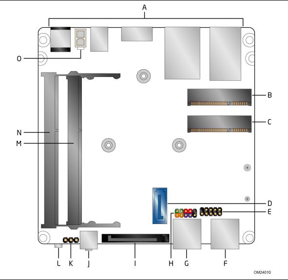
1.1.3Board Layout (Bottom)
Figure 2 shows the location of the major components on the bottom-side of Intel NUC Board D54250WYB and Intel NUC Board D34010WYB.
Figure 2. Major Board Components (Bottom)
15
Intel NUC Board D54250WYB and Intel NUC Board D34010WYB
Technical Product Specification
Table 3. Components Shown in Figure 2
Item from |
|
Figure 2 |
Description |
|
|
A |
Back panel connectors |
|
|
B |
PCI Express Full-Mini Card connector |
|
|
C |
PCI Express Half-Mini Card connector |
|
|
D |
SATA 6.0 Gb/s connector |
|
|
E |
Front panel dual-port USB 2.0 header (2.0 mm pitch) |
|
|
F |
Front panel USB 3.0 connector |
|
|
G |
Front panel USB 3.0 connector |
|
|
H |
Front panel header (2.0 mm pitch) |
|
|
I |
SATA power connector |
|
|
J |
Front panel stereo microphone/headphone jack |
|
|
K |
BIOS setup configuration jumper |
|
|
L |
Consumer Infrared (CIR) sensor |
|
|
M |
DDR3L SO-DIMM 2 socket |
|
|
N |
DDR3L SO-DIMM 1 socket |
|
|
O |
Internal DC power connector |
|
|
16

Product Description
1.1.4Block Diagram
Figure 3 is a block diagram of the major functional areas of the board.
Figure 3. Block Diagram
17
Intel NUC Board D54250WYB and Intel NUC Board D34010WYB Technical Product Specification
1.2 |
Online Support |
|
|
To find information about… |
Visit this World Wide Web site: |
|
Intel NUC Board D54250WYB and Intel |
http://www.intel.com/NUC |
|
NUC Board D34010WYB |
|
|
Intel NUC Board Support |
http://www.intel.com/NUCSupport |
|
Available configurations for Intel NUC |
http://ark.intel.com |
|
Board D54250WYB and Intel NUC |
|
|
Board D34010WYB |
|
|
BIOS and driver updates |
http://downloadcenter.intel.com |
|
Tested memory |
http://www.intel.com/NUCSupport |
|
Integration information |
http://www.intel.com/NUCSupport |
|
Processor datasheet |
http://ark.intel.com |
1.3Processor
•Intel NUC Board D54250WYB has a soldered-down Intel® Core™ i5-4250U processor with up to 15 W TDP
Integrated graphics
Integrated memory controller
Integrated PCH
•Intel NUC Board D34010WYB has a soldered-down Intel® Core™ i3-4010U processor with up to 15 W TDP
Integrated graphics
Integrated memory controller
Integrated PCH
 NOTE
NOTE
There are specific requirements for providing power to the processor. Refer to Section 2.5.1 on page 52 for information on power supply requirements.
18
Product Description
1.4System Memory
The board has two 204-pin SO-DIMM sockets and support the following memory features:
•1.35 V DDR3L SDRAM SO-DIMMs with gold plated contacts
•Two independent memory channels with interleaved mode support
•Unbuffered, single-sided or double-sided SO-DIMMs
•16 GB maximum total system memory (with 4 Gb memory technology). Refer to Section 2.1.1 on page 37 for information on the total amount of addressable memory.
•Minimum recommended total system memory: 1024 MB
•Non-ECC SO-DIMMs
•Serial Presence Detect
•DDR3L 1600 MHz and DDR3L 1333 MHz SDRAM SO-DIMMs
 NOTE
NOTE
To be fully compliant with all applicable DDR SDRAM memory specifications, the board should be populated with SO-DIMMs that support the Serial Presence Detect (SPD) data structure. This allows the BIOS to read the SPD data and program the chipset to accurately configure memory settings for optimum performance. If non-SPD memory is installed, the BIOS will attempt to correctly configure the memory settings, but performance and reliability may be impacted or the SO-DIMMs may not function under the determined frequency.
Table 4 lists the supported SO-DIMM configurations.
Table 4. Supported Memory Configurations
DIMM |
Configuration (Note) |
SDRAM |
SDRAM Organization |
Number of SDRAM |
|
Capacity |
Density |
Front-side/Back-side |
Devices |
||
4096 MB |
DS |
2 Gbit |
256 |
M x8/256 M x8 |
16 |
4096 MB |
SS |
4 Gbit |
512 |
M x8/empty |
8 |
8192 MB |
DS |
4 Gbit |
512 |
M x8/512 M x8 |
16 |
Note: “DS” refers to double-sided memory modules (containing two rows of SDRAM) and “SS” refers to single-sided memory modules (containing one row of SDRAM).
For information about… |
Refer to: |
|
|
Tested Memory |
http://www.intel.com/NUCSupport |
|
|
19
Intel NUC Board D54250WYB and Intel NUC Board D34010WYB
Technical Product Specification
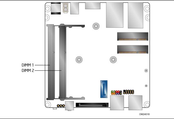
1.4.1Memory Configurations
The processor supports the following types of memory organization:
•Dual channel (Interleaved) mode. This mode offers the highest throughput for real world applications. Dual channel mode is enabled when the installed memory capacities of both SO-DIMM channels are equal. Technology and device width can vary from one channel to the other but the installed memory capacity for each channel must be equal. If different speed SO-DIMMs are used between channels, the slowest memory timing will be used.
•Single channel (Asymmetric) mode. This mode is equivalent to single channel bandwidth operation for real world applications. This mode is used when only a single SO-DIMM is installed or the memory capacities are unequal. Technology and device width can vary from one channel to the other. If different speed SO-DIMMs are used between channels, the slowest memory timing will be used.
For information about… |
Refer to: |
|
|
Memory Configuration Examples |
http://www.intel.com/NUCSupport |
|
|
Figure 4 illustrates the memory channel and SO-DIMM configuration.
Figure 4. Memory Channel and SO-DIMM Configuration
20
Product Description
1.5Processor Graphics Subsystem
The board supports graphics through Intel HD Graphics.
1.5.1Integrated Graphics
The board supports integrated graphics via the processor.
1.5.1.1Intel® High Definition (Intel® HD) Graphics
The Intel HD graphics controller features the following:
•3D Features
DirectX* 11 support
OpenGL* 4.0 support
•Video
•Next Generation Intel® Clear Video Technology HD support is a collection of video playback and enhancement features that improve the end user’s viewing experience
•Encode/transcode HD content
•Playback of high definition content including Blu-ray* disc
•Superior image quality with sharper, more colorful images
•Playback of Blu-ray disc S3D content using Mini HDMI (v1.4a spec compliant with 3D)
•DirectX* Video Acceleration (DXVA) support for accelerating video processing
•Full AVC/VC1/MPEG2 HW Decode
•Intel HD Graphics with Advanced Hardware Video Transcoding (Intel® Quick Sync Video)
 NOTE
NOTE
Intel Quick Sync Video is enabled by an appropriate software application.
1.5.1.2Video Memory Allocation
Intel® Dynamic Video Memory Technology (DVMT) is a method for dynamically allocating system memory for use as graphics memory to balance 2D/3D graphics and system performance. If your computer is configured to use DVMT, graphics memory is allocated based on system requirements and application demands (up to the configured maximum amount). When memory is no longer needed by an application, the dynamically allocated portion of memory is returned to the operating system for other uses.
21
Intel NUC Board D54250WYB and Intel NUC Board D34010WYB
Technical Product Specification
1.5.1.3Mini High Definition Multimedia Interface* (Mini HDMI*)
The Mini High-Definition Multimedia Interface (Mini HDMI) is provided for transmitting uncompressed digital audio and video signals to television sets, projectors and other video displays. It can carry high quality multi-channel audio data and all standard and high-definition consumer electronics video formats. The Mini HDMI display interface connecting the processor and display devices utilizes transition minimized differential signaling (TMDS) to carry audio visual information through the same Mini HDMI cable. The processor HDMI interface is designed according to the High-Definition Multimedia Interface Specification with 3D, Deep Color, and x.v.Color. The maximum supported resolution is 1920 x 1200 @ 60 Hz, 24bpp. The Mini HDMI port is compliant with the HDMI 1.4a specification.
1.5.1.4Mini DisplayPort*
DisplayPort is a digital communication interface that utilizes differential signaling to achieve a high bandwidth bus interface designed to support connections between PCs and monitors, projectors, and TV displays. DisplayPort is suitable for display connections between consumer electronics devices such as high definition optical disc players, set top boxes, and TV displays. The maximum supported resolution is 3840 x 2160 @ 30 Hz, 24bpp. The Mini DisplayPort interface supports the 1.2 specification.
The DisplayPort output supports Multi-Stream Transport (MST) which allows for multiple independent video streams (daisy-chain connection with multiple monitors) over a single DisplayPort. This will require the use of displays that support DisplayPort 1.2 and allow for this feature.
For information about |
Refer to |
|
|
DisplayPort technology |
http://www.displayport.org |
|
|
22
Product Description
1.5.1.4.1DisplayPort 1.2 Multi-Stream Transport Daisy-Chaining
Table 5 lists the maximum resolutions available when using DisplayPort 1.2 Multi-Stream Transport.
Table 5. DisplayPort Multi-Streaming Resolutions
DisplayPort Usage |
|
|
|
Models |
Monitor 1 |
Monitor 2 |
Monitor 3 |
|
|
|
|
3 Monitors |
1920 x 1200 @ 60 Hz |
1920 x 1080 @ 60 Hz |
1920 x 1080 @ 60 Hz |
|
|
|
|
2 Monitors |
2560 x 1600 @ 60 Hz |
2560 x 1600 @ 60 Hz |
|
|
|
|
|
3 Monitors |
1920 x 1080 @ 60 Hz |
1920 x 1080 @ 60 Hz |
1920 x 1080 @ 60 Hz |
(with DisplayPort 1.2 |
|
|
|
hub) |
|
|
|
|
|
|
|
1.5.1.5Multiple DisplayPort and HDMI Configurations
Multiple DisplayPort and HDMI configurations feature the following:
•Two independent displays
•Single HDMI 1.4a with 1080P support
•Single DisplayPort 1.2 with 4K support
•Collage Display
Table 6. Multiple Display Configuration Maximum Resolutions
Single Display |
Dual Display |
Single Display |
HDMI |
DisplayPort and HDMI |
DisplayPort |
|
|
|
1920 x 1200 @ 60 Hz |
3840 x 2160 @ 30 Hz (DisplayPort) |
3840 x 2160 @ 30 Hz |
|
1920 x 1200 @ 60 Hz (HDMI) |
|
|
|
|
Note: Higher resolutions may be achievable but have not been tested on Intel NUC.
For information about |
Refer to |
|
|
Multiple display maximum |
https://www- |
resolutions |
ssl.intel.com/content/www/us/en/processors/core/CoreTechnicalResou |
|
rces.html (Generic link) |
|
https://www-ssl.intel.com/content/www/us/en/processors/core/4th- |
|
gen-core-family-desktop-vol-1-datasheet (Specific Link) |
|
|
1.5.1.6High-bandwidth Digital Content Protection (HDCP)
HDCP is the technology for protecting high definition content against unauthorized copy or interception between a source (computer, digital set top boxes, etc.) and the sink (panels, monitor, and TVs). The PCH supports HDCP 1.4a for content protection over wired displays (Mini HDMI and Mini DisplayPort).
23
Intel NUC Board D54250WYB and Intel NUC Board D34010WYB
Technical Product Specification
1.5.1.7Integrated Audio Provided by the Mini HDMI and Mini DisplayPort Interfaces
The Mini HDMI and Mini DisplayPort interfaces from the PCH support audio. The processor supports two High Definition audio streams on two digital ports simultaneously.
Table 7 shows the specific audio technologies supported by the PCH.
Table 7. Audio Formats Supported by the Mini HDMI and
Mini DisplayPort Interfaces
Audio Formats |
Mini HDMI |
Mini DisplayPort |
|
|
|
AC-3 – Dolby* Digital |
Yes |
Yes |
|
|
|
Dolby Digital Plus |
Yes |
Yes |
|
|
|
DTS-HD* |
Yes |
Yes |
|
|
|
LPCM , 192 kHz/24 bit, 8 channel |
Yes |
Yes |
|
|
|
Dolby True HD, DTS-HD Master Audio* (Lossless Blu-ray Disc |
Yes |
Yes |
Audio Format) |
|
|
|
|
|
1.6USB
The board supports eight USB ports. All eight ports are high-speed, full-speed, and low-speed capable. The port arrangement is as follows:
•USB 3.0 ports:
Two front panel USB 3.0 ports are implemented through an external connector (blue)
Two ports are implemented with vertical back panel connectors (blue)
•USB 2.0 ports:
Two ports via one dual-port internal 2.0 mm pitch header (black)
One port is reserved for the PCI Express Half-Mini Card
One port is reserved for the PCI Express Full-Mini Card
 NOTE
NOTE
Computer systems that have an unshielded cable attached to a USB port may not meet FCC Class B requirements, even if no device is attached to the cable. Use a shielded cable that meets the requirements for full-speed devices.
For information about |
Refer to |
|
|
The location of the USB connectors on the back panel |
Figure 9, page 38 |
|
|
The location of the front panel USB headers |
Figure 2, page 15 |
|
|
24
Loading...