


 Loading...
Intel® NUC Products
NUC8i3BE/NUC8i5BE/NUC8i7BE
Technical Product Specification
Regulatory Models: NUC8BEK (Short Kit/Mini PC)
NUC8BEH (Tall Kit/Mini PC)
NUC8BEB (Board)
July 2018
Order Number: K15389-001
i

Intel NUC Products NUC8i3BE, NUC8i5BE and NUC8i7BE may contain design defects or errors known as errata that may cause the product to deviate from published specifications. Current characterized errata, if any, are documented in Intel NUC Products NUC8i3BE/NUC8i5BE/NUC8i7BE Specification Update.
Revision History
Revision |
Revision History |
Date |
|
|
|
001 |
First release of Intel NUC Products NUC8i3BE/NUC8i5BE/NUC8i7BE Technical |
April 2018 |
|
Product Specification |
|
|
|
|
002 |
First production release of the Intel NUC Products |
July 2018 |
|
NUC8i3BE/NUC8i5BE/NUC8i7BE Technical Product Specification |
|
|
|
|
Disclaimer
This product specification applies to only the standard Intel NUC Board, Kit or System with BIOS identifier BECFL357.86A.
INFORMATION IN THIS DOCUMENT IS PROVIDED IN CONNECTION WITH INTEL® PRODUCTS. NO LICENSE, EXPRESS OR IMPLIED, BY ESTOPPEL OR OTHERWISE, TO ANY INTELLECTUAL PROPERTY RIGHTS IS GRANTED BY THIS DOCUMENT. EXCEPT AS PROVIDED IN INTEL’S TERMS AND CONDITIONS OF SALE FOR SUCH PRODUCTS, INTEL ASSUMES NO LIABILITY WHATSOEVER, AND INTEL DISCLAIMS ANY EXPRESS OR IMPLIED WARRANTY, RELATING TO SALE AND/OR USE OF INTEL PRODUCTS INCLUDING LIABILITY OR WARRANTIES RELATING TO FITNESS FOR A PARTICULAR PURPOSE, MERCHANTABILITY, OR INFRINGEMENT OF ANY PATENT, COPYRIGHT OR OTHER INTELLECTUAL PROPERTY RIGHT. UNLESS OTHERWISE AGREED IN WRITING BY INTEL, THE INTEL PRODUCTS ARE NOT DESIGNED NOR INTENDED FOR ANY APPLICATION IN WHICH THE FAILURE OF THE INTEL PRODUCT COULD CREATE A SITUATION WHERE PERSONAL INJURY OR DEATH MAY OCCUR.
All Intel NUC Boards are evaluated as Information Technology Equipment (I.T.E.) for use in personal computers (PC) for installation in homes, offices, schools, computer rooms, and similar locations. The suitability of this product for other PC or embedded non-PC applications or other environments, such as medical, industrial, alarm systems, test equipment, etc. may not be supported without further evaluation by Intel.
Intel Corporation may have patents or pending patent applications, trademarks, copyrights, or other intellectual property rights that relate to the presented subject matter. The furnishing of documents and other materials and information does not provide any license, express or implied, by estoppel or otherwise, to any such patents, trademarks, copyrights, or other intellectual property rights.
Intel may make changes to specifications and product descriptions at any time, without notice.
Designers must not rely on the absence or characteristics of any features or instructions marked “reserved” or “undefined.” Intel reserves these for future definition and shall have no responsibility whatsoever for conflicts or incompatibilities arising from future changes to them.
Intel processor numbers are not a measure of performance. Processor numbers differentiate features within each processor family, not across different processor families: Go to:
Learn About Intel® Processor Numbers
Intel NUC may contain design defects or errors known as errata, which may cause the product to deviate from published specifications. Current characterized errata are available on request.
Contact your local Intel sales office or your distributor to obtain the latest specifications before placing your product order.
Intel, the Intel logo, Intel NUC and Intel Core are trademarks of Intel Corporation in the U.S. and/or other countries. * Other names and brands may be claimed as the property of others.
Copyright 2018 Intel Corporation. All rights reserved.
ii
Contents
Note: For this Technical Product Specification, the use of Intel NUC Products NUC8i3BE/NUC8i5BE/NUC8i7BE refers to Intel NUC Kit NUC8i3BEH, Intel NUC Kit NUC8i5BEH, Intel NUC Kit NUC8i7BEH, Intel NUC Kit NUC8i3BEK, Intel NUC Kit NUC8i5BEK, Intel NUC Mini PC NUC8i3BEKx, Intel NUC Mini PC NUC8i5BEKx, Intel NUC Mini PC NUC8i3BEHx, Intel NUC Mini PC NUC8i5BEHx, Intel NUC Mini PC NUC8i7BEHx, and Intel NUC Boards NUC8i3BEB, NUC8i5BEB and NUC8i7BEB.
Board Identification Information
Basic Intel® NUC Board NUC8i3BEB Identification Information
AA Revision |
BIOS Revision |
Notes |
|
|
|
J72693-303 |
BECFL357.86A.0038 |
1,2 |
|
|
|
Notes: |
|
|
1.The AA number is found on a small label on the SO-DIMM sockets.
2.The Intel® Core™ i3-8109U processor is used on this AA revision consisting of the following component:
Device |
Stepping |
S-Spec Numbers |
|
|
|
Intel Core i3-8109U |
D0 |
SRCKC |
|
|
|
Basic Intel® NUC Board NUC8i5BEB Identification Information
AA Revision |
BIOS Revision |
Notes |
|
|
|
J72692-303 |
BECFL357.86A.0038 |
1,2 |
|
|
|
Notes: |
|
|
1.The AA number is found on a small label on the SO-DIMM sockets.
2.The Intel® Core™ i5-8259U processor is used on this AA revision consisting of the following component:
Device |
Stepping |
S-Spec Numbers |
|
|
|
Intel Core i5-8259U |
D0 |
SRCKB |
|
|
|
Basic Intel® NUC Board NUC8i7BEB Identification Information
AA Revision |
BIOS Revision |
Notes |
|
|
|
J72688-303 |
BECFL357.86A.0038 |
1,2 |
|
|
|
Notes: |
|
|
1.The AA number is found on a small label on the SO-DIMM sockets.
2.The Intel® Core™ i7-8559U processor is used on this AA revision consisting of the following component:
Device |
Stepping |
S-Spec Numbers |
|
|
|
Intel Core i7-8559U |
D0 |
SRCK5 |
|
|
|
iii
Product Identification Information
Intel® NUC Products NUC8i{x}BE{y}{z}1 Identification Information
Product Name |
Intel® NUC |
Differentiating Features |
|
Board |
|
|
|
|
NUC8i3BEK |
|
Kit with power adapter |
|
|
|
NUC8i3BEH |
NUC8i3BEB |
HDD-capable kit with power adapter |
|
|
|
NUC8i3BEHXF |
J72693-303 |
HDD kit with power adapter, 16GB Intel® Optane™ Module, 1TB HDD, |
|
4GB DDR4-2400 SDRAM[2], Microsoft Windows 10 Home, “Intel® NUC |
|
|
|
|
|
|
8 Home, a Mini PC with Windows 10” |
|
|
|
NUC8i5BEK |
|
Kit with power adapter |
|
|
|
NUC8i5BEH |
NUC8i5BEB |
HDD-capable kit with power adapter |
|
|
|
NUC8i5BEHXF |
J72692-303 |
HDD kit with power adapter, 16GB Intel® Optane™ Module, 1TB HDD, |
|
4GB DDR4-2400 SDRAM[2], Microsoft Windows 10 Home, “Intel® NUC |
|
|
|
|
|
|
8 Home, a Mini PC with Windows 10” |
|
|
|
NUC8i7BEH |
|
HDD-capable kit with power adapter |
|
NUC8i7BEB |
|
NUC8i7BEHXG |
32GB Intel® Optane™ Module, 2TB HDD, 8GB DDR4-2400 SDRAM[2], |
|
|
J72688-303 |
Microsoft* Windows* 10 Home, “Intel® NUC 8 Enthusiast, a Mini PC |
|
|
with Windows 10” |
|
|
|
Notes: |
|
|
1.Where {x} = 3|5|7; {y} = “K” for “slim kit”, “H” for “tall kit”; and {z} = “XF” | “XG” for “Intel Optane system”
2.The maximum supported memory speed of the Intel NUC Board NUC8i[x]BEB is 2400 MHz.
Specification Changes or Clarifications
The table below indicates the Specification Changes or Specification Clarifications that apply to the Intel NUC Products NUC8i3BE, NUC8i5BE and NUC8i7BE.
Specification Changes or Clarifications
Date |
Type of Change |
Description of Changes or Clarifications |
|
|
|
|
|
|
Errata
Current characterized errata, if any, are documented in a separate Specification Update. See http://www.intel.com/content/www/us/en/nuc/overview.html for the latest documentation.
iv

Contents
Preface
This Technical Product Specification (TPS) specifies the board layout, components, connectors, power and environmental requirements, and the BIOS for Intel® NUC Board NUC8i3BEB, Intel® NUC Board NUC8i5BEB and Intel® NUC Board NUC8i7BEB.
Intended Audience
The TPS is intended to provide detailed, technical information about Intel® NUC Board NUC8i3BEB, Intel® NUC Board NUC8i5BEB and Intel® NUC Board NUC8i7BEB and its components to the vendors, system integrators, and other engineers and technicians who need this level of information. It is specifically not intended for general audiences.
What This Document Contains
Chapter |
Description |
|
|
1 |
A description of the features and hardware used on Intel NUC Board NUC8i3BEB, Intel NUC |
|
Board NUC8i5BEB and Intel NUC Board NUC8i7BEB |
|
|
2 |
A map of the resources of the Intel NUC Board |
|
|
3 |
The features supported by the BIOS Setup program |
|
|
4 |
A description of the BIOS error messages, beep codes, and POST codes |
5A description of the Intel NUC kit NUC8i3BE[x], Intel NUC kit NUC8i5BE[x] and Intel NUC kit
NUC8i7BEH features
Typographical Conventions
This section contains information about the conventions used in this specification. Not all of these symbols and abbreviations appear in all specifications of this type.
Notes, Cautions, and Warnings
 NOTE
NOTE
Notes call attention to important information.
CAUTION
Cautions are included to help you avoid damaging hardware or losing data.
v

Other Common Notation
# |
Used after a signal name to identify an active-low signal (such as USBP0#) |
|
|
GB |
Gigabyte (1,073,741,824 bytes) |
|
|
GBps |
Gigabytes per second |
|
|
Gbps |
Gigabits per second |
|
|
KB |
Kilobyte (1024 bytes) |
|
|
Kb |
Kilobit (1024 bits) |
|
|
kbps |
1000 bits per second |
|
|
MB |
Megabyte (1,048,576 bytes) |
|
|
MBps |
Megabytes per second |
|
|
Mb |
Megabit (1,048,576 bits) |
|
|
Mbps |
Megabits per second |
|
|
TDP |
Thermal Design Power |
|
|
Xxh |
An address or data value ending with a lowercase h indicates a hexadecimal value. |
|
|
x.x V |
Volts. Voltages are DC unless otherwise specified. |
*This symbol is used to indicate third-party brands and names that are the property of their respective owners.
vi
|
|
Contents |
|
Contents |
|
|
|
|
|
||
Revision History............................................................................................................... |
ii |
||
Disclaimer .................................................................................................................................................................. |
|
ii |
|
Note: For this Technical Product Specification, the use of Intel NUC Products |
|
||
|
NUC8i3BE/NUC8i5BE/NUC8i7BE refers to Intel NUC Kit NUC8i3BEH, Intel NUC Kit |
|
|
|
NUC8i5BEH, Intel NUC Kit NUC8i7BEH, Intel NUC Kit NUC8i3BEK, Intel NUC Kit |
|
|
|
NUC8i5BEK, Intel NUC Mini PC NUC8i3BEKx, Intel NUC Mini PC NUC8i5BEKx, Intel |
|
|
|
NUC Mini PC NUC8i3BEHx, Intel NUC Mini PC NUC8i5BEHx, Intel NUC Mini PC |
|
|
|
NUC8i7BEHx, and Intel NUC Boards NUC8i3BEB, NUC8i5BEB and NUC8i7BEB. ........... |
iii |
|
Board Identification Information..................................................................................................................... |
iii |
||
Product Identification Information................................................................................................................. |
iv |
||
Errata........................................................................................................................................................................... |
|
iv |
|
Preface ............................................................................................................................... |
|
v |
|
Intended Audience................................................................................................................................................. |
v |
||
What This Document Contains......................................................................................................................... |
v |
||
Typographical Conventions ............................................................................................................................... |
v |
||
Contents .......................................................................................................................... |
|
vii |
|
1 Product Description .................................................................................................. |
1 |
||
1.1 |
Overview ......................................................................................................................................................... |
1 |
|
|
1.1.1 |
Feature Summary ..................................................................................................................... |
1 |
|
1.1.2 |
Board Layout (Top) .................................................................................................................. |
3 |
|
1.1.3 |
Board Layout (Bottom) ........................................................................................................... |
4 |
|
1.1.4 |
Block Diagram ............................................................................................................................ |
6 |
1.2 |
Online Support............................................................................................................................................. |
7 |
|
1.3 |
Processor........................................................................................................................................................ |
8 |
|
1.4 |
System Memory ........................................................................................................................................... |
8 |
|
1.5 |
Processor Graphics Subsystem.......................................................................................................... |
11 |
|
|
1.5.1 |
Integrated Graphics .............................................................................................................. |
11 |
1.6 |
USB................................................................................................................................................................. |
|
14 |
1.7 |
SATA Interface........................................................................................................................................... |
14 |
|
|
1.7.1 |
AHCI Mode................................................................................................................................ |
15 |
|
1.7.2 |
Intel® Rapid Storage Technology / SATA RAID ......................................................... |
15 |
|
1.7.3 |
Intel® Next Generation Storage Acceleration............................................................. |
15 |
1.8 |
Thunderbolt 3............................................................................................................................................ |
16 |
|
1.9 |
Real-Time Clock Subsystem................................................................................................................ |
16 |
|
1.10 |
Audio Subsystem ..................................................................................................................................... |
16 |
|
|
1.10.1 |
Audio Subsystem Software ............................................................................................... |
17 |
1.11 |
LAN Subsystem......................................................................................................................................... |
17 |
|
vii
1.11.1 Intel® I219V Gigabit Ethernet Controller ..................................................................... |
17 |
|
1.11.2 |
LAN Subsystem Software................................................................................................... |
18 |
1.11.3 RJ-45 LAN Connector with Integrated LEDs.............................................................. |
18 |
|
1.11.4 |
Wireless Network Module.................................................................................................. |
19 |
1.12 Hardware Management Subsystem ................................................................................................. |
19 |
|
1.12.1 |
Hardware Monitoring ........................................................................................................... |
19 |
1.12.2 |
Fan Monitoring........................................................................................................................ |
19 |
1.12.3 |
Thermal Solution ................................................................................................................... |
19 |
1.13 Power Management ................................................................................................................................ |
20 |
|
1.13.1 |
ACPI............................................................................................................................................. |
21 |
1.13.2 |
Hardware Support................................................................................................................. |
23 |
1.13.3 Microsoft Modern Standby Support.............................................................................. |
26 |
|
1.14 Intel Platform Security Technologies .............................................................................................. |
26 |
|
1.14.1 |
Intel® Virtualization Technology...................................................................................... |
26 |
1.14.2 Intel® Platform Trust Technology ................................................................................... |
27 |
|
2 Technical Reference............................................................................................... |
28 |
||
2.1 |
Memory Resources .................................................................................................................................. |
28 |
|
|
2.1.1 |
Addressable Memory........................................................................................................... |
28 |
2.2 |
Connectors and Headers....................................................................................................................... |
28 |
|
|
2.2.1 |
Front Panel Connectors ...................................................................................................... |
29 |
|
2.2.2 |
Back Panel Connectors ....................................................................................................... |
29 |
|
2.2.3 |
Headers and Connectors (Top)........................................................................................ |
30 |
|
2.2.4 |
Connectors and Headers (Bottom)................................................................................. |
31 |
2.3 |
BIOS Security Jumper ............................................................................................................................ |
41 |
|
2.4 |
Mechanical Considerations .................................................................................................................. |
43 |
|
|
2.4.1 |
Form Factor.............................................................................................................................. |
43 |
2.5 |
Electrical Considerations ...................................................................................................................... |
44 |
|
|
2.5.1 |
Power Supply Considerations.......................................................................................... |
44 |
|
2.5.2 |
Fan Header Current Capability......................................................................................... |
44 |
2.6 |
Thermal Considerations........................................................................................................................ |
45 |
|
2.7 |
Reliability ..................................................................................................................................................... |
50 |
|
2.8 |
Environmental ........................................................................................................................................... |
50 |
|
3 Overview of BIOS Features................................................................................... |
51 |
||
3.1 |
Introduction................................................................................................................................................ |
51 |
|
3.2 |
BIOS Flash Memory Organization ..................................................................................................... |
51 |
|
3.3 |
System Management BIOS (SMBIOS).............................................................................................. |
51 |
|
3.4 |
Legacy USB Support ............................................................................................................................... |
52 |
|
3.5 |
BIOS Updates............................................................................................................................................. |
52 |
|
|
3.5.1 |
Language Support................................................................................................................. |
53 |
3.6 |
BIOS Recovery ........................................................................................................................................... |
53 |
|
3.7 |
Boot Options .............................................................................................................................................. |
54 |
|
|
3.7.1 |
Network Boot........................................................................................................................... |
54 |
viii
|
|
|
Contents |
|
3.7.2 |
Booting Without Attached Devices (Headless).......................................................... |
54 |
|
3.7.3 |
Changing the Default Boot Device during POST...................................................... |
54 |
|
3.7.4 |
Power Button Menu.............................................................................................................. |
55 |
3.8 |
Hard Disk Drive Password Security Feature.................................................................................. |
56 |
|
3.9 |
BIOS Security Features .......................................................................................................................... |
57 |
|
4 Error Messages and Blink Codes......................................................................... |
58 |
||
4.1 |
Front-panel Power LED Blink Codes................................................................................................ |
58 |
|
4.2 |
BIOS Error Messages............................................................................................................................... |
58 |
|
5 Intel NUC Kit Features ........................................................................................... |
59 |
||
5.1 |
Chassis Front Panel Features.............................................................................................................. |
59 |
|
5.3 |
Chassis Rear Panel Features................................................................................................................ |
61 |
|
ix
Figures |
|
Figure 1. Major Board Components (Top) .......................................................................................................... |
3 |
Figure 2. Major Board Components (Bottom) ................................................................................................... |
4 |
Figure 3. Block Diagram.............................................................................................................................................. |
6 |
Figure 4. Memory Channel and SO-DIMM Configuration.......................................................................... |
10 |
Figure 5. 4-Pin 3.5 mm (1/8 inch) Audio Jack Pin Out ............................................................................... |
17 |
Figure 6. LAN Connector LED Locations........................................................................................................... |
18 |
Figure 7. Thermal Solution and Fan Header................................................................................................... |
20 |
Figure 8. Location of the Standby Power LED ............................................................................................... |
25 |
Figure 9. Front Panel Connectors........................................................................................................................ |
29 |
Figure 10. Back Panel Connectors ...................................................................................................................... |
29 |
Figure 11. Headers and Connectors (Top)....................................................................................................... |
30 |
Figure 12. Connectors and Headers (Bottom) ............................................................................................... |
31 |
Figure 13. Connection Diagram for Front Panel Header (2.0 mm Pitch) ............................................ |
37 |
Figure 14. Connection Diagram for the Internal USB 2.0 Single-Port Header (1.25 mm Pitch)39 |
|
Figure 15. Location of the CIR Sensor............................................................................................................... |
39 |
Figure 16. Location of the BIOS Security Jumper ........................................................................................ |
41 |
Figure 17. Board Dimensions................................................................................................................................ |
43 |
Figure 18. Board Height Dimensions ................................................................................................................. |
44 |
Figure 19. Localized High Temperature Zones ............................................................................................. |
46 |
Figure 20. Installation Area of Thermal Pad for Intel NUC Kit NUC8i3BEK/NUC8i5BEK............. |
47 |
Figure 21. Installation area of Thermal Pad for Intel NUC Kit |
|
NUC8i3BEH/NUC8i5BEH/NUC8i7BEH...................................................................................................... |
48 |
Figure 22. Intel NUC Kit NUC8i3BEH/NUC8i5BEH/NUC8i7BEH Features – Front ........................... |
59 |
Figure 23. Intel NUC Kit NUC8i3BEK/NUC8i5BEK Features – Front ...................................................... |
60 |
Figure 24. Intel NUC Kit NUC8i3BEH/NUC8i5BEH/NUC8i7BEH Features – Rear............................. |
61 |
Figure 25. Intel NUC Kit NUC8i3BEK/NUC8i5BEK Features – Rear........................................................ |
62 |
Tables |
|
Table 1. Feature Summary........................................................................................................................................ |
1 |
Table 2. Components Shown in Figure 1............................................................................................................ |
3 |
Table 3. Components Shown in Figure 2............................................................................................................ |
5 |
Table 4. Supported Memory Configurations..................................................................................................... |
9 |
Table 5. Unsupported Memory Configurations................................................................................................ |
9 |
Table 6. DisplayPort Multi-Streaming Resolutions...................................................................................... |
12 |
Table 7. Multiple Display Configuration Maximum Resolutions ............................................................ |
13 |
Table 8. Audio Formats Supported by the HDMI and USB Type C Interfaces.................................. |
13 |
Table 9. LAN Connector LED States................................................................................................................... |
18 |
Table 10. Effects of Pressing the Power Switch............................................................................................ |
21 |
Table 11. Power States and Targeted System Power................................................................................. |
22 |
Table 12. Wake-up Devices and Events ........................................................................................................... |
23 |
Table 13. Headers and Connectors Shown in Figure 11........................................................................... |
30 |
Table 14. Connectors and Headers Shown in Figure 12........................................................................... |
32 |
x
|
Contents |
Table 15. SATA Power Connector (1.25 mm pitch)..................................................................................... |
33 |
Table 16. Single-Port Internal USB 2.0 Header (1.25 mm pitch) ........................................................... |
33 |
Table 17. M.2 2280 Module (key type M) Connector.................................................................................. |
33 |
Table 18. Digital Microphone (DMICS) Array Connector (1.25 mm Pitch).......................................... |
34 |
Table 19. RGB LED Connector (1.25 mm Pitch) ............................................................................................ |
35 |
Table 20. CEC Header (1.25 mm pitch)............................................................................................................. |
35 |
Table 21. USB Type C Connector......................................................................................................................... |
36 |
Table 22. Front Panel Header (2.0 mm Pitch)................................................................................................ |
36 |
Table 23. States for a One-Color Power LED ................................................................................................. |
37 |
Table 24. States for a Dual-Color Power LED ................................................................................................ |
37 |
Table 25. SDXC Card Reader Connector.......................................................................................................... |
38 |
Table 26. HDMI CEC expected behavior............................................................................................................ |
40 |
Table 27. RGB LED Options ................................................................................................................................... |
40 |
Table 28. Fan Header Current Capability......................................................................................................... |
44 |
Table 29. Thermal Considerations for Components................................................................................... |
49 |
Table 30. Tcontrol Values for Components ................................................................................................... |
49 |
Table 31. Environmental Specifications........................................................................................................... |
50 |
Table 32. Acceptable Drives/Media Types for BIOS Recovery ............................................................... |
53 |
Table 33. Boot Device Menu Options................................................................................................................ |
54 |
Table 34. Master Key and User Hard Drive Password Functions........................................................... |
56 |
Table 35. Supervisor and User Password Functions................................................................................... |
57 |
Table 36. Front-panel Power LED Blink Codes ............................................................................................. |
58 |
Table 37. Components Shown in Figure 22 ................................................................................................... |
59 |
Table 38. Components Shown in Figure 23 ................................................................................................... |
60 |
Table 39. Components Shown in Figure 24 ................................................................................................... |
61 |
Table 40. Components Shown in Figure 25 ................................................................................................... |
62 |
xi

1 Product Description
1.1Overview
1.1.1Feature Summary
Table 1 summarizes the major features of Intel® NUC Board NUC8i3BEB, Intel® NUC Board NUC8i5BEB and Intel® NUC Board NUC8i7BEB.
Table 1. Feature Summary
Form Factor |
4.0 inches by 4.0 inches (101.60 millimeters by 101.60 millimeters) |
|
|
|
|
Processor |
• A soldered-down 8th generation Intel® Core™ i3-8109U dual-core processor with a |
|
(one of 3 models) |
maximum 28 W TDP, 3.0 GHz base, 3.6 GHz Turbo, 4 threads |
|
― Intel® Iris™ Plus Graphics 655 |
||
|
||
|
― Integrated memory controller |
|
|
― Integrated PCH |
|
|
• A soldered-down 8th generation Intel® Core™ i5-8259U quad-core processor with a |
|
|
maximum 28 W TDP, 2.3 GHz base, 3.8 GHz Turbo, 8 threads |
|
|
― Intel® Iris™ Plus Graphics 655 |
|
|
― Integrated memory controller |
|
|
― Integrated PCHA |
|
|
• A soldered-down 8th generation Intel® Core™ i7-8559U quad-core processor with a |
|
|
maximum 28 W TDP, 2.7 GHz base, 4.5 GHz Turbo, 8 threads |
|
|
― Intel® Iris™ Plus Graphics 655 |
|
|
― Integrated memory controller |
|
|
― Integrated PCH |
|
|
|
|
Memory |
• Two 260-pin 1.2 V DDR4 SDRAM Small Outline Dual Inline Memory Module (SO-DIMM) |
|
|
sockets |
|
|
• Support for DDR4 2400 MHz SO-DIMMs |
|
|
• Support for 4 Gb and 8 Gb memory technology |
|
|
• Support for up to 32 GB of system memory with two SO-DIMMs using 8 Gb memory |
|
|
technology |
|
|
• Support for non-ECC memory |
|
|
• Support for 1.2 V low voltage JEDEC memory only |
|
|
Note: 2 Gb memory technology (SDRAM Density) is not compatible |
|
|
|
|
Graphics |
• Integrated graphics support for processors with Intel® Graphics Technology: |
|
|
― One High Definition Multimedia Interface* (HDMI*) back panel connector |
|
|
― One DisplayPort signal via USB Type C back panel connector |
|
|
|
|
Audio |
• Intel® High Definition (Intel® HD) Audio via the HDMI v2.0 and USB Type C interfaces |
|
|
through the processor |
|
|
• Realtek HD Audio via a stereo microphone/headphone 3.5 mm jack on the front panel |
|
|
• Digital microphone array (DMICS) connector (internal) |
|
|
|
|
Storage |
• SATA ports: |
|
|
― One SATA 6.0 Gbps port (black) for 2.5“ storage device |
|
|
• One SATA 6.0 Gbps port is reserved for an M.2 storage module supporting M.2 2242 |
|
|
and M.2 2280 (key type M and B+M) modules |
|
|
Note: Supports key type M and B+M (PCI Express* x1/x2/x4 and SATA) |
|
|
|
|
|
continued |
1
Table 1. Feature Summary (continued)
Peripheral Interfaces |
• One USB 3.1 (Gen 2/10 Gbps) port implemented via the external back panel Type C |
|
|
|
connector |
|
• USB 3.1 (Gen 2/10 Gbps) Type A ports: |
|
|
|
• Two ports are implemented with external front panel connectors (one blue and one |
|
|
orange charging capable) |
|
|
• Two ports are implemented with external back panel connectors (blue) |
|
• |
USB 2.0 ports: |
|
|
• Two ports via two single-port internal 1x4 1.25 mm pitch headers (white) |
|
|
• One port is reserved for the NGFF 1216 Wireless module Bluetooth capability |
|
• |
Consumer Infrared (CIR) |
|
|
|
Expansion Capabilities |
• One M.2 connector supporting M.2 2242 and M.2 2280 (key type M and B+M) modules |
|
|
• One Micro SDXC slot |
|
|
• One Thunderbolt™ 3 via back panel USB Type C connector |
|
|
|
|
BIOS |
• Intel® BIOS resident in the Serial Peripheral Interface (SPI) Flash device |
|
|
• Support for Advanced Configuration and Power Interface (ACPI), Plug and Play, System |
|
|
|
Management BIOS (SMBIOS), and Modern Standby |
|
|
|
Instantly Available PC |
• Suspend to RAM support |
|
Technology |
• Wake on PCI Express, LAN, front panel, CIR, and USB ports |
|
|
|
|
LAN |
Gigabit (10/100/1000 Mbps) LAN subsystem using the Intel® I219V Gigabit Ethernet |
|
|
Controller |
|
|
|
|
Hardware Monitor |
Hardware monitoring subsystem, based on an ITE Tech. IT8987E-VG embedded controller, |
|
Subsystem |
including: |
|
|
• Voltage sense to detect out of range power supply voltages |
|
|
• Thermal sense to detect out of range thermal values |
|
|
• One processor fan header |
|
|
• Fan sense input used to monitor fan activity |
|
|
• |
Fan speed control |
|
|
|
Wireless |
Intel® Dual Band Wireless-AC 9560 |
|
|
• 802.11ac, Dual Band, 2x2 Wi-Fi + Bluetooth 5 |
|
|
• Maximum Transfer speed up to 1.73 Gbps |
|
|
• Supports Intel® Smart Connect Technology |
|
|
• Next Generation Form Factor (NGFF) 12x16 soldered-down package |
|
|
|
|
2
Intel NUC Kit Features
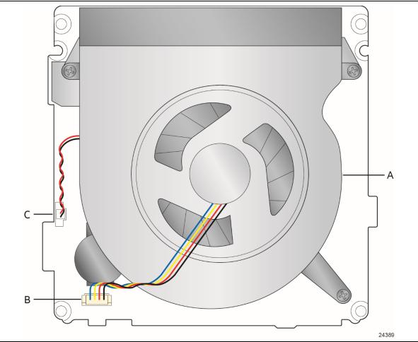
1.1.2Board Layout (Top)
Figure 1 shows the location of the major components on the top-side of Intel NUC Board NUC8i3BEB, Intel NUC Board NUC8i5BEB and Intel NUC Board NUC8i7BEB.
Figure 1. Major Board Components (Top)
Table 2 lists the components identified in Figure 1.
Table 2. Components Shown in Figure 1
Item from Figure 1 |
Description |
|
|
A |
Thermal solution |
|
|
B |
Processor fan header |
|
|
C |
Battery connector |
|
|
3

1.1.3Board Layout (Bottom)
Figure 2 shows the location of the major components on the bottom-side of Intel NUC Board NUC8i3BEB, Intel NUC Board NUC8i5BEB and Intel NUC Board NUC8i7BEB.
Figure 2. Major Board Components (Bottom)
4
Intel NUC Kit Features
Table 3. Components Shown in Figure 2
Item from Figure 2 |
|
|
Description |
|
|
A |
DC Input Jack |
|
|
B |
HDMI connector |
|
|
C |
LAN connector |
|
|
D |
USB 3.1 ports (blue) |
|
|
E |
Digital Microphones (DMICs) header |
|
|
F |
Front Panel header |
|
|
G |
Intel Dual Band Wireless AC + Bluetooth 9560 module |
|
|
H |
RGB (HDD) LED header |
|
|
I |
Micro SDXC slot |
|
|
J |
SATA power connector (1.25 mm pitch) |
|
|
K |
M.2 connector (key type M and B+M) for 2242 and 2280 modules |
|
|
L |
Front panel single-port USB 2.0 header (1.25 mm pitch) |
|
|
M |
HDD Activity LED |
|
|
N |
Front panel single-port USB 2.0 header (1.25 mm pitch) |
|
|
O |
Front panel USB 3.1 connector (blue) |
|
|
P |
Standby LED |
|
|
Q |
Front panel USB 3.1 connector (orange, charging) |
|
|
R |
SATA 6.0 Gbps connector |
|
|
S |
Front panel stereo microphone/headphone jack |
|
|
T |
Consumer Infrared (CIR) sensor |
|
|
U |
Front panel power button |
|
|
V |
BIOS security header & jumper |
|
|
W |
Consumer electronics control (CEC) header |
|
|
X |
DDR4 SO-DIMM1 socket |
|
|
Y |
DDR4 SO-DIMM2 socket |
|
|
5

1.1.4Block Diagram
Figure 3 is a block diagram of the major functional areas of the board.
Figure 3. Block Diagram
6
1.2Online Support
To find information about…
Intel NUC Board NUC8i3BEB, Intel NUC Board NUC8i5BEB, and Intel NUC Board NUC8i7BEB
Intel NUC Support
Available configurations for Intel NUC Board NUC8i3BEB, Intel NUC Board NUC8i5BEB and Intel NUC Board NUC8i7BEB
Product support page NUC8i3BEK
Product support page NUC8i3BEH
Product support page NUC8i5BEK
Product support page NUC8i5BEH
Product support page NUC8i7BEH
BIOS and driver updates
BIOS and driver updates for NUC8i3BEK
BIOS and driver updates for NUC8i3BEH
BIOS and driver updates for NUC8i5BEK
BIOS and driver updates for NUC8i5BEH
BIOS and driver updates for NUC8i7BEH
Tested memory
Compatible peripherals and components
Integration information
Processor datasheet
Regulatory documentation
Intel NUC Kit Features
Visit this Intel web site:
http://www.intel.com/NUC
http://www.intel.com/NUCSupport
http://ark.intel.com
https://www.intel.com/content/www/us/en/support /boards-and-kits/intel-nuc-kits/intel-nuc-kit-nuc8i3bek.html
http://www.intel.com/content/www/us/en/support /boards-and-kits/intel-nuc-kits/intel-nuc-kit-nuc8i3beh.html
https://www.intel.com/content/www/us/en/support/boards-and- kits/intel-nuc-boards/intel-nuc-board-nuc8i5bek.html
http://www.intel.com/content/www/us/en/support /boards-and-kits/intel-nuc-kits/intel-nuc-kit-nuc8i5beh.html
http://www.intel.com/content/www/us/en/support /boards-and-kits/intel-nuc-kits/intel-nuc-kit-nuc8i7beh.html
http://downloadcenter.intel.com https://downloadcenter.intel.com/product/126149 https://downloadcenter.intel.com/product/126150 https://downloadcenter.intel.com/product/126147 https://downloadcenter.intel.com/product/126148 https://downloadcenter.intel.com/product/126140
http://www.intel.com/content/www/us/en/support/boards-and- kits/ 000027798.html
https://www.intel.com/content/www/us/en/support/articles/000 027966.html
http://www.intel.com/NUCSupport http://ark.intel.com
https://www.intel.com/content/www/us/en/support/articles/000 028043.html
7

1.3Processor
One of the following:
A soldered-down 8th generation Intel® Core™ i3-8109U dual-core processor with up to a maximum 28 W TDP (if thermal margin is available).
•3.0 GHz base frequency, 3.6 GHz turbo frequency, 4 threads
•Intel® Iris™ Plus Graphics 655
•Integrated memory controller
•Integrated PCH
A soldered-down 8th generation Intel® Core™ i5-8259U quad-core processor with up to a maximum 28 W TDP (if thermal margin is available).
•2.3 GHz base frequency, 3.8 GHz turbo frequency, 8 threads
•Intel® Iris™ Plus Graphics 655
•Integrated memory controller
•Integrated PCH
A soldered-down 8th generation Intel® Core™ i7-8559U quad-core processor with up to a maximum 28 W TDP (if thermal margin is available).
•2.7 GHz base frequency, 4.5 GHz turbo frequency, 8 threads
•Intel® Iris™ Plus Graphics 655
•Integrated memory controller
•Integrated PCH
 NOTE
NOTE
There are specific requirements for providing power to the processor. Refer to Section 2.5.1 on page 44 for information on power supply requirements.
1.4System Memory
The board has two 260-pin SO-DIMM sockets and supports the following memory features:
•1.2 V DDR4 SDRAM SO-DIMMs with gold plated contacts
•Two independent memory channels with interleaved mode support
•Unbuffered, single-sided or double-sided SO-DIMMs
•32 GB maximum total system memory (with 8 Gb memory technology). Refer to Section 2.1.1 on page 28 for information on the total amount of addressable memory.
•Minimum recommended total system memory: 2048 MB
•Non-ECC SO-DIMMs
•Serial Presence Detect
•DDR4 2400 MHz SDRAM SO-DIMMs
•Supports 4 Gb and 8Gb memory technology (SDRAM density)
8
Intel NUC Kit Features
 NOTE
NOTE
To be fully compliant with all applicable DDR SDRAM memory specifications, the board should be populated with SO-DIMMs that support the Serial Presence Detect (SPD) data structure. This allows the BIOS to read the SPD data and program the chipset to accurately configure memory settings for optimum performance. If non-SPD memory is installed, the BIOS will attempt to correctly configure the memory settings, but performance and reliability may be impacted or the SO-DIMMs may not function under the determined frequency.
 NOTE
NOTE
Intel NUC Boards NUC8i3BEB, NUC8i5BEB and NUC8i7BEB support only 4 Gb and 8 Gb memory technologies (also referred to as “SDRAM density”). Table 4 lists the supported SO-DIMM configurations. Table 5 lists the SO-DIMM configurations that are not supported.
Table 4. Supported Memory Configurations
SO-DIMM |
|
SDRAM |
SDRAM Organization |
Number of SDRAM |
Capacity |
Configuration (Note) |
Density |
Front-side/Back-side |
Devices |
2048 MB |
SS |
4 Gbit |
512 M x4/empty |
4 |
4096 MB |
DS |
4 Gbit |
512 M x4/512 M x4 |
8 |
4096 MB |
SS |
8 Gbit |
1024 M x4/empty |
4 |
8192 MB |
DS |
4 Gbit |
512 M x8/512 M x8 |
16 |
8192 MB |
DS |
8 Gbit |
1024 M x4/1024 M x4 |
8 |
16384 MB |
DS |
8 Gbit |
1024 M X8/1024 M x8 |
16 |
Note: “DS” refers to double-sided memory modules and “SS” refers to single-sided memory modules.
Table 5. Unsupported Memory Configurations
SO-DIMM |
|
SDRAM |
SDRAM Organization |
Number of SDRAM |
Capacity |
Configuration (Note) |
Density |
Front-side/Back-side |
Devices |
1024 MB |
SS |
1 Gbit |
128 M x8/empty |
8 |
2048 MB |
DS |
1 Gbit |
128 M x8/128 M x8 |
16 |
2048 MB |
SS |
2 Gbit |
256 M x8/empty |
8 |
4096 MB |
DS |
2 Gbit |
256 M x8/256 M x8 |
16 |
Note: “DS” refers to double-sided memory modules and “SS” refers to single-sided memory modules.
For information about… |
Refer to: |
|
|
Tested Memory |
http://www.intel.com/content/www/us/en/support/boards-and- |
|
kits/ 000027798.html |
|
|
9
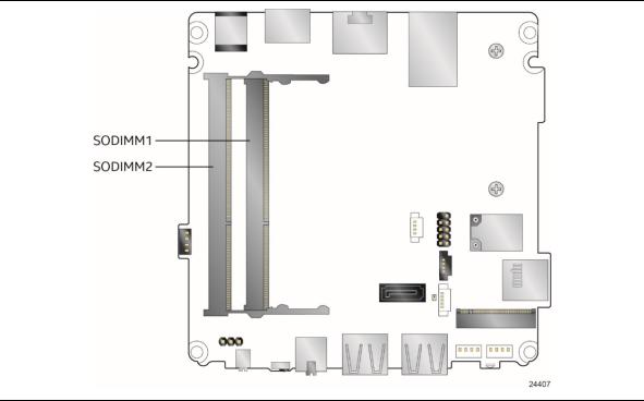
Figure 4 illustrates the memory channel and SO-DIMM configuration.
Figure 4. Memory Channel and SO-DIMM Configuration
10

Intel NUC Kit Features
1.5Processor Graphics Subsystem
The Intel NUC Boards NUC8i3BEB, NUC8i5BEB and NUC8i7BEB support graphics through Intel Iris™ Plus Graphics 655.
1.5.1Integrated Graphics
The board supports integrated graphics via the processor.
1.5.1.1Intel® High Definition (Intel® HD) Graphics
The Intel Iris™ Plus graphics controller features the following:
•API support
―Direct3D* 2015, Direct3D 11.2, Direct3D 11.1, Direct3D 9, Direct3D 10, Direct2D
―OpenGL* 4.5 support
―OpenCL* 2.1 , OpenCL 2.0, OpenCL 1.2 support
•Next Generation Intel® Clear Video Technology HD support is a collection of video playback and enhancement features that improve the end user’s viewing experience
•Encode/transcode HD content
•Playback of high definition content including Blu-ray* disc
•Superior image quality with sharper, more colorful images
•DirectX* Video Acceleration (DXVA2) support for accelerating video processing
•Full AVC/VC1/MPEG2/HEVC/VP8/VP9/JPEG hardware-accelerated video decode
•Full AVC/MPEG2/HEVC/VP8/JPEG hardware-accelerated video encode
•Intel HD Graphics with Advanced Hardware Video Transcoding (Intel® Quick Sync Video)
 NOTES
NOTES
Intel Quick Sync Video is enabled by an appropriate software application.
HDMI 2.0a is enabled by LSPCON (DP 1.2 to HDMI 2.0a protocol converter); Stereo 3D (S3D) technology is not supported.
HDMI 2.0a supports High Dynamic Range (HDR) and 10-bit sampling. HDR requires use of appropriate software and display hardware.
1.5.1.2Video Memory Allocation
Intel® Dynamic Video Memory Technology (DVMT) is a method for dynamically allocating system memory for use as graphics memory to balance 2D/3D graphics and system performance. If your computer is configured to use DVMT, graphics memory is allocated based on system requirements and application demands (up to the configured maximum amount). When memory is no longer needed by an application, the dynamically allocated portion of memory is returned to the operating system for other uses.
11
Loading...