


 Loading...
Intel® Desktop Board D850GB
Technical Product Specification
April 2001
Order Number A26080-002
The Intel®Desktop Board D850GB may contain design defects or errors known as errata that may cause the product to deviate from published specifications. Current characterized errata are documented in the Intel Desktop Board D850GB Specification Update.

Revision History
Revision |
Revision History |
Date |
-001 |
First release of the Intel®Desktop Board D850GB Technical Product |
September 2000 |
|
Specification. |
|
-002 |
Second release of the Intel Desktop Board D850GB Technical Product |
April 2001 |
|
Specification. Changes include (but not limited to) the following: |
|
|
∙ Added caution statement in processor section regarding the use of |
|
|
ATX12V-compliant power supplies |
|
|
∙ Changed Firmware Hub component to SST 49LF004A |
|
|
∙ Added AD1885 analog codec as an option to audio subsystem |
|
|
∙ Listed Diagnostic LEDs as a manufacturing option |
|
|
∙ Updated fan connector section |
|
|
∙ Updated BIOS Setup program chapter to reflect latest version of BIOS |
|
|
∙ Included document changes from the most recent specification update |
|
This product specification applies to only standard D850GB boards with BIOS identifier GB85010A.86A.
Changes to this specification will be published in the Intel Desktop Board D850GB Specification Update before being incorporated into a revision of this document.
Information in this document is provided in connection with Intel® products. No license, express or implied, by estoppel or otherwise, to any intellectual property rights is granted by this document. Except as provided in Intel’s Terms and Conditions of Sale for such products, Intel assumes no liability whatsoever, and Intel disclaims any express or implied warranty, relating to sale and/or use of Intel products including liability or warranties relating to fitness for a particular purpose, merchantability, or infringement of any patent, copyright or other intellectual property right. Intel products are not intended for use in medical, life saving, or life sustaining applications.
Intel may make changes to specifications and product descriptions at any time, without notice.
The Intel® Desktop Board D850GB may contain design defects or errors known as errata that may cause the product to deviate from published specifications. Current characterized errata are available on request.
Contact your local Intel sales office or your distributor to obtain the latest specifications before placing your product order.
Copies of documents which have an ordering number and are referenced in this document, or other Intel literature, may be obtained from:
Intel Corporation
P.O. Box 5937
Denver, CO 80217-9808
or call in North America 1-800-548-4725, Europe 44-0-1793-431-155, France 44-0-1793-421-777, Germany 44-0-1793-421-333, other Countries 708-296-9333.
† Third-party brands and names are the property of their respective owners.
Copyright © 2000, 2001, Intel Corporation. All rights reserved.

Preface
This Technical Product Specification (TPS) specifies the board layout, components, connectors, power and environmental requirements, and the BIOS for the Intel Desktop Board D850GB. It describes the standard product and available manufacturing options.
Intended Audience
The TPS is intended to provide detailed, technical information about the D850GB board and its components to the vendors, system integrators, and other engineers and technicians who need this level of information. It is specifically not intended for general audiences.
What This Document Contains
Chapter Description
1A description of the hardware used on the D850GB board
2A map of the resources of the board
3The features supported by the BIOS Setup program
4The contents of the BIOS Setup program’s menus and submenus
5A description of the BIOS error messages, beep codes, POST codes, and diagnostic LEDs
Typographical Conventions
This section contains information about the conventions used in this specification. Not all of these symbols and abbreviations appear in all specifications of this type.
Notes, Cautions, and Warnings
NOTE
Notes call attention to important information.
CAUTION
Cautions are included to help you avoid damaging hardware or losing data.
WARNING
Warnings indicate conditions, which if not observed, can cause personal injury.
iii

Intel Desktop Board D850GB Technical Product Specification
Other Common Notation
#Used after a signal name to identify an active-low signal (such as USBP0#)
(NxnX) |
When used in the description of a component, N indicates component type, xn are the relative |
|
coordinates of its location on the D850GB board, and X is the instance of the particular part at |
|
that general location. For example, J5J1 is a connector, located at 5J. It is the first connector |
|
in the 5J area. |
GB |
Gigabyte (1,073,741,824 bytes) |
GB/sec |
Gigabytes per second |
KB |
Kilobyte (1024 bytes) |
Kbit |
Kilobit (1024 bits) |
kbits/sec |
1000 bits per second |
MB |
Megabyte (1,048,576 bytes) |
MB/sec |
Megabytes per second |
Mbit |
Megabit (1,048,576 bits) |
Mbit/sec |
Megabits per second |
xxh |
An address or data value ending with a lowercase h indicates a hexadecimal value. |
x.x V |
Volts. Voltages are DC unless otherwise specified. |
†This symbol is used to indicate third-party brands and names that are the property of their respective owners.
iv

Contents
1 Product Description
1.1 |
Overview .................................................................................................................... |
12 |
|
|
1.1.1 |
Feature Summary ........................................................................................ |
12 |
|
1.1.2 |
Manufacturing Options ................................................................................. |
13 |
|
1.1.3 |
D850GB Board Layout ................................................................................. |
14 |
|
1.1.4 |
Block Diagram.............................................................................................. |
15 |
1.2 |
Online Support ........................................................................................................... |
16 |
|
1.3 |
Design Specifications ................................................................................................. |
16 |
|
1.4 |
Processor ................................................................................................................... |
19 |
|
1.5 |
System Memory ......................................................................................................... |
20 |
|
|
1.5.1 |
Memory Features ......................................................................................... |
20 |
|
1.5.2 |
Continuity RIMM Modules ............................................................................ |
20 |
|
1.5.3 |
RDRAM Memory Configuration .................................................................... |
21 |
1.6 |
Intel® 850 Chipset....................................................................................................... |
22 |
|
|
1.6.1 |
AGP ............................................................................................................. |
23 |
|
1.6.2 |
USB.............................................................................................................. |
23 |
|
1.6.3 |
IDE Support ................................................................................................. |
24 |
|
1.6.4 |
Real-Time Clock, CMOS SRAM, and Battery............................................... |
25 |
|
1.6.5 |
SST 49LF004A 4 Mbit Firmware Hub (FWH) ............................................... |
25 |
1.7 |
I/O Controller .............................................................................................................. |
26 |
|
|
1.7.1 |
Serial Port .................................................................................................... |
26 |
|
1.7.2 |
Parallel Port.................................................................................................. |
26 |
|
1.7.3 |
Diskette Drive Controller .............................................................................. |
27 |
|
1.7.4 |
Keyboard and Mouse Interface .................................................................... |
27 |
1.8 |
Audio Subsystem (Optional) ....................................................................................... |
28 |
|
|
1.8.1 |
Audio Connectors......................................................................................... |
29 |
|
1.8.2 |
Audio Subsystem Software .......................................................................... |
29 |
1.9 |
LAN Subsystem.......................................................................................................... |
30 |
|
|
1.9.1 |
Intel® 82562EM Platform LAN Connect Device (Optional)............................ |
30 |
|
1.9.2 |
RJ-45 LAN Connector with Integrated LEDs (Optional)................................ |
30 |
|
1.9.3 |
LAN Subsystem Software ............................................................................ |
31 |
1.10 CNR (Optional) ........................................................................................................... |
31 |
||
1.11 Hardware Management Subsystem............................................................................ |
32 |
||
|
1.11.1 |
Hardware Monitor Component ..................................................................... |
32 |
|
1.11.2 |
Fan Control and Monitoring.......................................................................... |
32 |
1.12 Power Management ................................................................................................... |
33 |
||
|
1.12.1 |
Software Support ......................................................................................... |
33 |
|
1.12.2 |
Hardware Support ........................................................................................ |
37 |
2 Technical Reference
2.1 |
Introduction................................................................................................................. |
43 |
2.2 |
Memory Map .............................................................................................................. |
43 |
2.3 |
I/O Map ...................................................................................................................... |
44 |
v
Intel Desktop Board D850GB Technical Product Specification
2.4 |
DMA Channels ........................................................................................................... |
46 |
|
2.5 |
PCI Configuration Space Map .................................................................................... |
46 |
|
2.6 |
Interrupts .................................................................................................................... |
47 |
|
2.7 |
PCI Interrupt Routing Map.......................................................................................... |
47 |
|
2.8 |
Connectors ................................................................................................................. |
49 |
|
|
2.8.1 |
Back Panel Connectors................................................................................ |
50 |
|
2.8.2 |
Internal I/O Connectors ................................................................................ |
53 |
|
2.8.3 |
External I/O Connectors ............................................................................... |
65 |
2.9 |
Jumper Blocks............................................................................................................ |
68 |
|
|
2.9.1 |
BIOS Setup Configuration Jumper Block...................................................... |
69 |
|
2.9.2 |
USB Port 2 Routing Jumper Block ............................................................... |
69 |
2.10 |
Mechanical Considerations......................................................................................... |
70 |
|
|
2.10.1 |
Form Factor ................................................................................................. |
70 |
|
2.10.2 |
I/O Shield ..................................................................................................... |
71 |
2.11 |
Electrical Considerations ............................................................................................ |
72 |
|
|
2.11.1 |
Power Consumption ..................................................................................... |
72 |
|
2.11.2 |
Add-in Board Considerations........................................................................ |
72 |
|
2.11.3 |
Standby Current Requirements .................................................................... |
73 |
|
2.11.4 |
Fan Connector Current Capability ................................................................ |
74 |
|
2.11.5 |
Power Supply Considerations ...................................................................... |
74 |
2.12 |
Thermal Considerations.............................................................................................. |
75 |
|
2.13 |
Reliability .................................................................................................................... |
76 |
|
2.14 |
Environmental ............................................................................................................ |
77 |
|
2.15 |
Regulatory Compliance .............................................................................................. |
78 |
|
|
2.15.1 |
Safety Regulations ....................................................................................... |
78 |
|
2.15.2 |
EMC Regulations ......................................................................................... |
78 |
|
2.15.3 |
Certification Markings................................................................................... |
79 |
3 Overview of BIOS Features
3.1 |
Introduction................................................................................................................. |
81 |
|
3.2 |
BIOS Flash Memory Organization .............................................................................. |
82 |
|
3.3 |
Resource Configuration .............................................................................................. |
82 |
|
|
3.3.1 |
PCI Autoconfiguration .................................................................................. |
82 |
|
3.3.2 |
PCI IDE Support........................................................................................... |
82 |
3.4 |
System Management BIOS (SMBIOS) ....................................................................... |
83 |
|
3.5 |
Legacy USB Support .................................................................................................. |
83 |
|
3.6 |
BIOS Updates ............................................................................................................ |
84 |
|
|
3.6.1 |
Language Support........................................................................................ |
84 |
|
3.6.2 |
Custom Splash Screen................................................................................. |
85 |
3.7 |
Recovering BIOS Data ............................................................................................... |
85 |
|
3.8 |
Boot Options............................................................................................................... |
86 |
|
|
3.8.1 |
CD-ROM and Network Boot ......................................................................... |
86 |
|
3.8.2 |
Booting Without Attached Devices ............................................................... |
86 |
3.9 |
Fast Booting Systems with Intel® Rapid BIOS Boot.................................................... |
86 |
|
|
3.9.1 |
Peripheral Selection and Configuration ........................................................ |
86 |
|
3.9.2 |
Intel Rapid BIOS Boot .................................................................................. |
87 |
|
3.9.3 |
Operating System ........................................................................................ |
87 |
3.10 |
BIOS Security Features.............................................................................................. |
88 |
|
vi
Contents
4 BIOS Setup Program
4.1 |
Introduction................................................................................................................. |
89 |
|
4.2 |
Maintenance Menu ..................................................................................................... |
90 |
|
|
4.2.1 |
Extended Configuration Submenu................................................................ |
91 |
4.3 |
Main Menu.................................................................................................................. |
92 |
|
4.4 |
Advanced Menu.......................................................................................................... |
93 |
|
|
4.4.1 |
Boot Configuration Submenu ....................................................................... |
94 |
|
4.4.2 |
Peripheral Configuration Submenu............................................................... |
95 |
|
4.4.3 |
IDE Configuration Submenu......................................................................... |
97 |
|
4.4.4 |
Diskette Configuration Submenu................................................................ |
100 |
|
4.4.5 |
Event Log Configuration Submenu............................................................. |
101 |
|
4.4.6 |
Video Configuration Submenu.................................................................... |
102 |
4.5 |
Security Menu .......................................................................................................... |
103 |
|
4.6 |
Power Menu ............................................................................................................. |
104 |
|
4.7 |
Boot Menu ................................................................................................................ |
105 |
|
4.8 |
Exit Menu ................................................................................................................. |
107 |
|
5 Error Messages and Beep Codes
5.1 |
BIOS Error Messages............................................................................................... |
109 |
5.2 |
Port 80h POST Codes.............................................................................................. |
111 |
5.3 |
Bus Initialization Checkpoints ................................................................................... |
115 |
5.4 |
Speaker ................................................................................................................... |
116 |
5.5 |
BIOS Beep Codes .................................................................................................... |
116 |
5.6 |
Diagnostic LEDs (Optional) ...................................................................................... |
118 |
Figures
1. |
D850GB Board Components ...................................................................................... |
14 |
2. |
Block Diagram ............................................................................................................ |
15 |
3. |
Intel 850 Chipset Block Diagram................................................................................. |
22 |
4. |
Audio Subsystem Block Diagram................................................................................ |
28 |
5. |
ICH2 and CNR Signal Interface .................................................................................. |
31 |
6. |
Using the Wake on LAN Technology Connector......................................................... |
39 |
7. |
Location of the Standby Power Indicator LED ............................................................ |
40 |
8. |
Back Panel Connectors .............................................................................................. |
50 |
9. |
Audio Connectors ....................................................................................................... |
54 |
10. Power and Hardware Control Connectors .................................................................. |
56 |
|
11. |
Add-in Board and Peripheral Interface Connectors..................................................... |
59 |
12. |
External I/O Connectors ............................................................................................. |
65 |
13. |
Location of the Jumper Blocks.................................................................................... |
68 |
14. |
D850GB Board Dimensions........................................................................................ |
70 |
15. |
I/O Shield Dimensions ................................................................................................ |
71 |
16. |
Localized High Temperature Zones............................................................................ |
75 |
17. |
Diagnostic LEDs ....................................................................................................... |
118 |
vii
Intel Desktop Board D850GB Technical Product Specification
Tables |
|
|
1. |
Feature Summary....................................................................................................... |
12 |
2. |
Manufacturing Options ............................................................................................... |
13 |
3. |
Specifications ............................................................................................................. |
16 |
4. |
Supported Processors ................................................................................................ |
19 |
5. |
Supported Memory Configurations ............................................................................. |
21 |
6. |
LAN Connector LED States ........................................................................................ |
30 |
7. |
Effects of Pressing the Power Switch ......................................................................... |
34 |
8. |
Power States and Targeted System Power ................................................................ |
35 |
9. |
Wake Up Devices and Events .................................................................................... |
36 |
10. |
Fan Connector Descriptions ....................................................................................... |
38 |
11. |
System Memory Map.................................................................................................. |
43 |
12. |
I/O Map ...................................................................................................................... |
44 |
13. |
DMA Channels ........................................................................................................... |
46 |
14. |
PCI Configuration Space Map .................................................................................... |
46 |
15. |
Interrupts .................................................................................................................... |
47 |
16. |
PCI Interrupt Routing Map.......................................................................................... |
48 |
17. |
PS/2 Mouse/Keyboard Connector .............................................................................. |
51 |
18. |
USB Connectors......................................................................................................... |
51 |
19. |
Parallel Port Connector............................................................................................... |
51 |
20. |
Serial Port Connector ................................................................................................. |
52 |
21. |
LAN Connector (optional) ........................................................................................... |
52 |
22. |
Audio Line In Connector (optional) ............................................................................. |
52 |
23. |
Audio Line Out Connector (optional)........................................................................... |
52 |
24. |
Mic In Connector (optional)......................................................................................... |
52 |
25. |
Optional Auxiliary Line In Connector (J2C1) ............................................................... |
55 |
26. |
Optional ATAPI CD-ROM Connector (J2D1) .............................................................. |
55 |
27. |
Optional CD-ROM Legacy Style Connector (J2D2) .................................................... |
55 |
28. |
PC/PCI Connector (J6D1) .......................................................................................... |
55 |
29. |
ATX12V Power Connector (J3H1) .............................................................................. |
57 |
30. |
Processor Voltage Regulator Fan Connector (J3M1) ................................................. |
57 |
31. |
RIMM Fan Connector (J7M2) ..................................................................................... |
57 |
32. |
Processor Fan Connector (J6L1)................................................................................ |
57 |
33. |
Main Power Connector (J10K1).................................................................................. |
58 |
34. |
Auxiliary Power (J9J1) ................................................................................................ |
58 |
35. |
Wake on Ring Connector (J8C1) ................................................................................ |
58 |
36. |
Wake on LAN Technology Connector (J7C1) ............................................................. |
58 |
37. |
Chassis Fan Connector (J10A2)................................................................................. |
58 |
38. |
CNR Connector (J3A1)............................................................................................... |
60 |
39. |
PCI Bus Connectors (J4A1, J4B1, J4C1, J4D1, J4E1) ............................................... |
61 |
40. |
AGP Connector (J5E1)............................................................................................... |
62 |
41. |
PCI IDE Connectors (J9G2, Primary and J9G1, Secondary) ...................................... |
63 |
42. |
Diskette Drive Connector (J10G1) .............................................................................. |
64 |
43. |
SCSI LED Connector (J7A2) ...................................................................................... |
66 |
44. |
Front Panel USB Connector (J9C1)............................................................................ |
66 |
45. |
Auxiliary Front Panel Power/Sleep/Message Waiting LED Connector (J8C3)............. |
66 |
46. |
Front Panel Connector (J9D2).................................................................................... |
66 |
viii
Contents
47. |
States for a One Color Power LED ............................................................................. |
67 |
48. |
States for a Two Color Power LED ............................................................................. |
67 |
49. |
BIOS Setup Configuration Jumper Settings (J8C2) .................................................... |
69 |
50. |
USB Port 2 Routing Jumper Settings (J8D1) .............................................................. |
69 |
51. |
Power Usage.............................................................................................................. |
72 |
52. |
Standby Current Requirements .................................................................................. |
73 |
53. |
Thermal Considerations for Components ................................................................... |
76 |
54. |
D850GB Board Environmental Specifications............................................................. |
77 |
55. |
Safety Regulations ..................................................................................................... |
78 |
56. |
EMC Regulations........................................................................................................ |
78 |
57. |
Supervisor and User Password Functions .................................................................. |
88 |
58. |
BIOS Setup Program Menu Bar ................................................................................. |
89 |
59. |
BIOS Setup Program Function Keys .......................................................................... |
90 |
60. |
Maintenance Menu ..................................................................................................... |
90 |
61. |
Extended Configuration Submenu .............................................................................. |
91 |
62. |
Main Menu.................................................................................................................. |
92 |
63. |
Advanced Menu.......................................................................................................... |
93 |
64. |
Boot Configuration Submenu...................................................................................... |
94 |
65. |
Peripheral Configuration Submenu............................................................................. |
95 |
66. |
IDE Configuration Submenu ....................................................................................... |
97 |
67. |
Primary/Secondary IDE Master/Slave Submenus....................................................... |
98 |
68. |
Diskette Configuration Submenu .............................................................................. |
100 |
69. |
Event Log Configuration Submenu ........................................................................... |
101 |
70. |
Video Configuration Submenu .................................................................................. |
102 |
71. |
Security Menu .......................................................................................................... |
103 |
72. |
Power Menu ............................................................................................................. |
104 |
73. |
Boot Menu ................................................................................................................ |
105 |
74. |
Exit Menu ................................................................................................................. |
107 |
75. |
BIOS Error Messages............................................................................................... |
109 |
76. |
Uncompressed INIT Code Checkpoints.................................................................... |
111 |
77. |
Boot Block Recovery Code Checkpoints .................................................................. |
111 |
78. |
Runtime Code Uncompressed in F000 Shadow RAM .............................................. |
112 |
79. |
Bus Initialization Checkpoints ................................................................................... |
115 |
80. |
Upper Nibble High Byte Functions............................................................................ |
115 |
81. |
Lower Nibble High Byte Functions............................................................................ |
116 |
82. |
Beep Codes.............................................................................................................. |
117 |
83. |
Diagnostic LED Codes.............................................................................................. |
119 |
ix
Intel Desktop Board D850GB Technical Product Specification
x
1 Product Description
What This Chapter Contains |
|
|
1.1 |
Overview .................................................................................................................... |
12 |
1.2 |
Online Support ........................................................................................................... |
16 |
1.3 |
Design Specifications ................................................................................................. |
16 |
1.4 |
Processor ................................................................................................................... |
19 |
1.5 |
System Memory ......................................................................................................... |
20 |
1.6 |
Intel® 850 Chipset....................................................................................................... |
22 |
1.7 |
I/O Controller .............................................................................................................. |
26 |
1.8 |
Audio Subsystem (Optional) ....................................................................................... |
28 |
1.9 |
LAN Subsystem.......................................................................................................... |
30 |
1.10 |
CNR (Optional) ........................................................................................................... |
31 |
1.11 |
Hardware Management Subsystem............................................................................ |
32 |
1.12 |
Power Management ................................................................................................... |
33 |
11

Intel Desktop Board D850GB Technical Product Specification
1.1 Overview
1.1.1Feature Summary
Table 1 summarizes the D850GB board’s major features.
Table 1. Feature Summary
Form Factor
Processor
Memory
Chipset
I/O Control
Video
Peripheral
Interfaces
Expansion
Capabilities
BIOS
Instantly Available
PC
Wake on LAN†
Technology
Connector
Hardware Monitoring features
Enhanced thermal monitor and fan control device
ATX (12.0 inches by 9.6 inches)
∙Support for an Intel®Pentium®4 processor
∙400 MHz system data bus
∙Two Direct-RDRAM banks with two RIMM†s per bank (four RIMM sockets)
∙Support for up to 2 GB of system memory using PC600 or PC800 RDRAM
Intel®850 Chipset, consisting of:
∙Intel®82850 Memory Controller Hub (MCH)
∙Intel®82801BA I/O Controller Hub (ICH2)
∙SST 49LF004A 4 Mbit Firmware Hub (FWH) SMSC LPC47M102 LPC bus I/O controller
∙AGP connector supporting 1.5 V 4X AGP cards
∙Four Universal Serial Bus (USB) ports
∙One serial port
∙One parallel port
∙Two IDE interfaces with Ultra DMA, ATA-33/66/100 support
∙One diskette drive interface
∙PS/2† keyboard and mouse ports
∙Five PCI bus add-in card connectors (SMBus routed to PCI bus connector 2)
∙Intel/AMI BIOS (resident in the SST 49LF004A 4 Mbit FWH)
∙Support for Advanced Power Management (APM), Advanced Configuration and Power Interface (ACPI), Plug and Play, and SMBIOS
∙Support for PCI Local Bus Specification Revision 2.2
∙Suspend to RAM support
∙Wake on PCI, CNR, RS-232, front panel, PS/2 keyboard, and USB ports
Support for system wake up using an add-in network interface card with remote wake up capability
Two fan sense inputs used to monitor fan activity
∙Two additional fan sense inputs
∙Two additional thermal sense inputs
For information about |
Refer to |
The board’s compliance level with APM, ACPI, Plug and Play, and SMBIOS. |
Section 1.3, page 16 |
|
|
12

Product Description
1.1.2Manufacturing Options
Table 2 describes the D850GB board’s manufacturing options. Not every manufacturing option is available in all marketing channels. Please contact your Intel representative to determine which manufacturing options are available to you.
Table 2. Manufacturing Options
Audio (Integrated)
Video
LAN
Hardware Monitor
Subsystem
CNR
Diagnostic LEDs
Audio subsystem that uses the Analog Devices AD1881/AD1885 analog codec for AC 97 processing
AGP Pro50 interface (50 W maximum); backward compatible with 1.5 V AGP video cards.
This option uses an AGP Pro 1.5 V connector, also known as an AGP Pro50 connector.
Intel®82562EM 10/100 Mbit/sec Platform LAN Connect (PLC) device
Heceta 4 Hardware Monitor:
∙Voltage sense to detect out of range power supply voltages
∙Thermal sense to detect out of range thermal values
One Communication and Networking Riser (CNR) connector (slot shared with PCI bus connector 5, J4A1)
Four dual-color LEDs on back panel
13
Intel Desktop Board D850GB Technical Product Specification
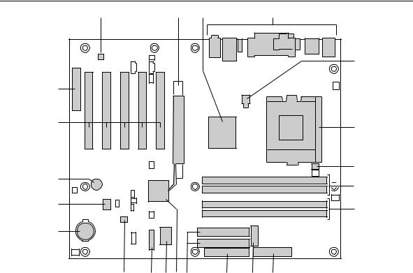
1.1.3D850GB Board Layout
Figure 1 shows the location of the major components on the D850GB board.
A |
|
B |
C |
|
|
D |
|
|
|
|
|
|
E |
V |
|
|
|
|
|
|
U |
|
|
|
|
|
F |
|
|
|
|
|
|
|
|
|
|
|
|
|
G |
T |
|
|
|
|
|
H |
|
|
|
|
|
|
|
S |
|
|
|
|
|
I |
|
|
|
|
|
|
|
R |
|
|
|
|
|
|
Q |
P |
O N M |
|
L |
K |
J |
|
|
|
|
|
|
OM10441 |
A |
AD1881/AD1885 audio codec (optional) |
L |
Diskette drive connector |
B |
AGP connector (AGP Pro 1.5V connector |
M |
IDE connectors |
|
optional) |
N |
Intel 82801BA I/O Controller Hub (ICH2) |
C |
Intel 82850 Memory Controller Hub (MCH) |
O SMSC LPC47M102 I/O Controller |
|
D |
Back panel connectors |
P |
Front panel connector |
E |
+12V power connector (ATX12V) |
Q Enhanced thermal monitor and fan control device |
|
F |
Pentium 4 Processor socket |
R |
Battery |
G |
Hardware monitor |
S |
SST 49LF004A 4 Mbit Firmware Hub (FWH) |
H |
RAMBUS† Bank 0 (RIMM1 and RIMM2) |
T |
Speaker |
I |
RAMBUS Bank 1 (RIMM3 and RIMM4) |
U PCI bus add-in card connectors |
|
J |
Power connector |
V |
Communication and Networking Riser (CNR) |
K |
Auxiliary Power connector |
|
connector (optional) |
|
|
|
|
Figure 1. D850GB Board Components
14

Product Description
1.1.4Block Diagram
Figure 2 is a block diagram of the major functional areas of the D850GB board.
Diagnostic
LEDs
Primary/ (Optional)
ATA-33/66/100
Secondary IDE
|
|
|
|
|
|
|
|
|
|
|
|
|
|
|
|
|
|
|
|
USB |
|
|
USB Ports 0 and 1 |
|
|
|
|
|
|
|
|
|
|
|||||
|
|
|
|
|
|
|
|
|
|
|
||
|
|
|
|
|
|
|
|
|
|
|
|
|
PGA423 |
|
|
System Bus |
|
|
|
|
|
|
|
|
|
|
|
|
|
|
|
|
|
|
USB Ports 2 and 3 |
|||
|
|
|
|
|
|
|
|
|
||||
Processor Socket |
|
|
(400 MHz) |
|
|
|
|
|
|
|
||
|
|
|
|
|
|
|
|
|
|
|
|
|
|
|
|
850 Chipset |
|
|
AGP |
|
82850 Memory |
AHA |
82801BA |
SST 49LF004A |
|
Controller Hub |
I/O Controller Hub |
Firmware Hub |
||
Interface |
|
Bus |
|||
|
(MCH) |
(ICH2) |
(FWH) |
||
|
|
|
|||
|
|
Dual RAMBUS |
|
LPC |
|
4X AGP |
|
|
Bus |
|
|
|
Channels |
|
CSMA/CD |
|
|
Connector |
|
|
|
Diskette Drive |
|
|
|
|
Unit |
||
(1.5 V only) |
|
|
|
||
|
|
|
Connector |
||
|
|
|
Interface |
||
|
|
|
|
||
or |
|
|
|
|
|
|
RAMBUS Bank 0 |
|
|
|
|
AGP Pro50 |
(RIMM1 and RIMM2) |
|
|
Serial Port |
|
|
|
|
|
||
Connector |
|
RAMBUS Bank 1 |
LPC I/O |
Parallel Port |
|
(optional) |
|
(RIMM3 and RIMM4) |
Controller |
PS/2 Mouse |
|
|
|
|
|
|
PS/2 Keyboard |
Hardware |
|
|
|
|
|
Monitors |
|
SMBus |
|
Physical |
LAN |
(optional) |
|
|
|
||
|
|
|
|
Layer |
Connector |
|
|
|
|
Interface |
(optional) |
|
|
PCI Bus |
|
|
CNR |
|
|
|
|
AC Link |
Connector |
|
|
|
|
(optional) |
|
PCI Slot 1 |
|
|
|
|
|
PCI Slot 2 |
|
|
|
AD1881/ |
CD-ROM |
|
|
|
|
||
PCI Slot 3 |
|
|
|
AD1885 |
Line In |
|
|
|
|
Audio |
Line Out |
PCI Slot 4 |
|
|
Codec |
Mic In |
|
|
|
|
|
(optional) |
Auxiliary Line In |
PCI Slot 5
= connector or socket
OM11731
Figure 2. Block Diagram
15
Intel Desktop Board D850GB Technical Product Specification
1.2 Online Support
To find information about… |
Visit this World Wide Web site: |
|
Intel’s D850GB board under “Product Info” or |
|
http://www.intel.com/design/motherbd |
“Customer Support” |
|
http://support.intel.com/support/motherboards/desktop |
|
|
|
Processor data sheets |
|
http://www.intel.com/design/litcentr |
|
|
|
Proper date access in systems with Intel® |
|
http://support.intel.com/support/year2000 |
motherboards |
|
|
ICH2 addressing
Custom splash screens
Audio software and utilities
LAN software and drivers
http://developer.intel.com/design/chipsets/datashts
http://intel.com/design/motherbd/gen_indx.htm
http://www.intel.com/design/motherbd
http://www.intel.com/design/motherbd
1.3 Design Specifications
Table 3 lists the specifications applicable to the D850GB board.
Table 3. Specifications
Reference
Name
AC ‘97
ACPI
AGP
AMI BIOS
APM
ATA/ ATAPI-5
Specification |
Version, Revision Date, |
The information is |
Title |
and Ownership |
available from… |
Audio Codec ‘97 |
Version 2.1, |
ftp://download.intel.com/ial/ |
|
May 1998, |
scalableplatforms/ac97r22.pdf |
|
Intel Corporation |
|
Advanced Configuration |
Version 2.0, |
http://www.teleport.com/~acpi/ |
and Power Interface |
July 27, 2000, |
|
Specification |
Compaq Computer Corp., |
|
|
Intel Corporation, |
|
|
Microsoft Corporation, |
|
|
and Toshiba Corporation |
|
Accelerated Graphics Port |
Version 2.0, |
http://www.agpforum.org/ |
Interface Specification |
May 4, 1998, |
|
|
Intel Corporation |
|
American Megatrends |
AMIBIOS 99, |
http://www.amij.com/amibios/ |
BIOS Specification |
1999 |
bios.platforms.desktop.html |
|
American Megatrends, Inc. |
|
Advanced Power |
Version 1.2, |
http://www.microsoft.com/ |
Management BIOS |
February 1996, |
hwdev/busbios/amp_12.htm |
Interface Specification |
Intel Corporation and |
|
|
Microsoft Corporation |
|
Information Technology - |
Revision 3 |
http://www.t13.org |
AT Attachment with Packet |
February 29, 2000, |
|
Interface -5, |
Contact: T13 Chair, |
|
(ATA/ATAPI-5) |
Seagate Technology |
|
continued
16

Product Description
Table 3. |
Specifications (continued) |
|
|
|
|
|
|
|
|
Reference |
|
Specification |
Version, Revision Date and |
The information is |
Name |
|
Title |
Ownership |
available from… |
ATX |
|
ATX Specification |
Version 2.03, |
http://www.formfactors.org/ |
|
|
|
December 1998, |
developer/specs/atx/ |
|
|
|
Intel Corporation. |
atxspecs.htm |
ATX12V |
|
ATX / ATX12V Power |
Version 1.1, |
http://www.formfactors.org/ |
|
|
Supply Design Guide |
August 2000, |
developer/specs/atx/ |
|
|
|
Intel Corporation |
atxspecs.htm |
BIS |
|
Boot Integrity Services |
Version 1.0 for WfM 2.0 |
http://developer.intel.com/ |
|
|
|
August 1999, |
design/security/bis/ |
|
|
|
Intel Corporation |
bisfaq.htm |
CNR |
|
Communication and |
Version 1.1, |
http://developer.intel.com/ |
|
|
Network Riser (CNR) |
October 18, 2000, |
technology/cnr/index.htm |
|
|
Specification |
Intel Corporation. |
|
EPP |
|
IEEE std 1284.1-1997 |
Version 1.7, |
http://standards.ieee.org/ |
|
|
Enhanced Parallel Port |
1997, |
reading/ieee/std_public/ |
|
|
|
Institute of Electrical and |
description/busarch/ |
|
|
|
Electronic Engineers |
1284.1-1997_desc.html |
El Torito |
|
Bootable CD-ROM |
Version 1.0, |
http://www.ptltd.com/ |
|
|
format specification |
January 25, 1995, |
techs/specs.html |
|
|
|
Phoenix Technologies Ltd., and |
|
|
|
|
IBM Corporation |
|
LPC |
|
Low Pin Count Interface |
Version 1.0, |
http://www.intel.com/ |
|
|
Specification |
September 29, 1997, |
design/chipsets/industry/ |
|
|
|
Intel Corporation |
lpc.htm |
PCI |
|
PCI Local Bus |
Version 2.2, |
http://www.pcisig.com/ |
|
|
Specification |
December 18, 1998, |
|
|
|
|
PCI Special Interest Group |
|
|
|
PCI Bus Power |
Version 1.1, |
http://www.pcisig.com/ |
|
|
Management Interface |
December 18, 1998, |
|
|
|
Specification |
PCI Special Interest Group |
|
Plug and |
|
Plug and Play BIOS |
Version 1.0a, |
http://www.microsoft.com/ |
Play |
|
Specification |
May 5, 1994, |
hwdev/respec/ |
|
|
|
Compaq Computer Corp., |
pnpspecs.htm |
|
|
|
Phoenix Technologies Ltd., |
|
|
|
|
and Intel Corporation |
|
PXE |
|
Preboot Execution |
Version 2.1, |
http://developer.intel.com/ |
|
|
Environment |
September 1999, |
ial/WfM/wfm20/design/ |
|
|
|
Intel Corporation |
mapxe/index.htm |
RIMM |
|
Rambus Serial Presence |
Version 1.0, |
http://www.rambus.com/ |
|
|
Detect (SPD) |
March 1999, |
developer/ |
|
|
Specification |
Rambus Corp. |
support_rimm.html |
|
|
Rambus RIMM |
Version 1.0, |
http://www.rambus.com/ |
|
|
Specification |
February 1999, |
developer/ |
|
|
|
Rambus Corp. |
development_support.html |
continued
17

Intel Desktop Board D850GB Technical Product Specification
Table 3. |
Specifications (continued) |
|
|
|
|
|
|
|
|
Reference |
|
Specification |
Version, Revision Date |
The information is |
Name |
|
Title |
and Ownership |
available from… |
SMBIOS |
|
System Management |
Version 2.3.1, |
http://developer.intel.com/ |
|
|
BIOS |
March 16, 1999, |
ial/wfm/design/smbios |
|
|
|
American Megatrends Inc., |
|
|
|
|
Award Software International Inc., |
|
|
|
|
Compaq Computer Corporation |
|
|
|
|
Dell Computer Corporation, |
|
|
|
|
Hewlett-Packard Company, |
|
|
|
|
Intel Corporation, |
|
|
|
|
International Business Machines |
|
|
|
|
Corporation, |
|
|
|
|
Phoenix Technologies Limited, |
|
|
|
|
and SystemSoft Corporation. |
|
UHCI |
|
Universal Host Controller |
Version 1.1, |
http://www.usb.org/ |
|
|
Interface Design Guide |
March 1996, |
developers |
|
|
|
Intel Corporation |
|
USB |
|
Universal Serial Bus |
Version 1.1, |
http://www.usb.org/ |
|
|
Specification |
September 23, 1998, |
developers |
|
|
|
Compaq Computer Corporation, |
|
|
|
|
Intel Corporation, |
|
|
|
|
Microsoft Corporation, and |
|
|
|
|
NEC Corporation |
|
WfM |
|
Wired for Management |
Version 2.0, |
http://developer.intel.com/ |
|
|
Baseline |
December 18, 1998, |
ial/WfM/wfmspecs.htm |
|
|
|
Intel Corporation |
|
18
Product Description
1.4 Processor
CAUTION
Use only the processors listed below. Use of unsupported processors can damage the D850GB board, the processor, and the power supply. See the Intel®Desktop Board 850GB Specification Update for the most up-to-date list of supported processors for the D850GB board.
The D850GB board supports a single Pentium 4 processor with a system bus of 400 MHz. The D850GB board supports the processors listed in Table 4. All supported onboard memory can be cached, up to the cachability limit of the processor. See the processor’s data sheet for cachability limits.
Table 4. Supported Processors
Type |
Designation |
System Bus |
L2 Cache Size |
Pentium 4 processor |
1.3, 1.4, and 1.5 GHz |
400 MHz |
256 KB |
CAUTION
Use only an ATX12V-compliant power suppIy with this board. ATX12V power supplies have two additional power leads that provide required supplemental power for the Intel Pentium 4 processor and the Intel 850 chipset. Always connect both additional power supply leads of the ATX12V power supply, otherwise the board and the processor could be damaged.
Do not use a standard ATX power supply. Doing so could damage the board and the processor.
For information about
Processor support
Processor usage
Power supply connectors
Refer to
Section 1.2, page 16
Section 1.2, page 16
Section 2.8.2.3, page 56
19

Intel Desktop Board D850GB Technical Product Specification
1.5 System Memory
CAUTION
Turn off the power and unplug the power cord before installing or removing RIMM modules. Failure to do so could damage the memory and the D850GB board. (After removing AC power the standby power indicator LED should not be lit. See Figure 7 on page 40 for the location of the standby power indicator LED.)
NOTE
The board supports combinations of no more than 32 RDRAM components per RDRAM bank. If the total number of RDRAM components installed in all RIMM sockets exceeds 64, the computer will not boot.
1.5.1Memory Features
The 82850 Memory Controller Hub integrates two lock-stepped Direct Rambus banks, providing a processor-to-memory bandwidth up to 3.2 GB/sec. The D850GB board has four RIMM sockets (two sockets for each bank) and supports the following memory features:
∙Singleor double-sided RIMM configurations
∙Maximum of 32 Direct Rambus devices per bank
∙Memory configurations from 128 MB (minimum) to 2 GB (maximum) utilizing 128 Mbit or 256 Mbit technology PC600 or PC800 compliant RDRAM
∙Serial Presence Detect (SPD) based configuration for optimal memory operation
∙Suspend to RAM support
∙ECC and non-ECC support
1.5.2Continuity RIMM Modules
All RIMM sockets must be populated to achieve continuity for termination at the Rambus interface. Continuity RIMMs (or “pass-through” modules) must be installed in the second RDRAM bank if memory is not installed. If any of the RIMM sockets are not populated, the computer will not complete the Power-On Self-Test (POST) and the BIOS beep codes will not be heard.
20
Product Description
1.5.3RDRAM Memory Configuration
When installing memory, note the following:
·The four RIMM sockets are grouped into two banks:
¾Bank 0 (labeled on the board as RIMM1 and RIMM2)
¾Bank 1 (labeled on the board as RIMM3 and RIMM4)
·Bank 0 must be populated first ensuring that the RDRAM installed in RIMM1 and RIMM2 is identical in speed, size, and density. For example, the minimum system configuration would use two 64 MB RIMM modules of PC600 or PC800 RDRAM.
·If the desired memory configuration has been achieved by populating Bank 0, then Bank 1 should be filled with two Continuity RIMMs.
·If memory is to be installed in Bank 1, the RIMM modules installed in RIMM3 and RIMM4 must be identical in size and density to each other, and match the speed of the RIMM modules in Bank 0. The RIMM modules do not, however, need to match those in Bank 0 in size and density. For example, if Bank 0 has two 128 MB RIMMs of PC800 RDRAM, Bank 1 would require PC800 RDRAM also, however, any other supported RIMM modules such as 64 MB or 192 MB could be used.
·If ECC functionality is required, all installed RIMM modules must be ECC-compliant
Table 5 gives examples of RDRAM component density for various RIMM modules. Component density (counts) can be identified on the RIMM label.
Table 5. Supported Memory Configurations
|
Capacity with |
Capacity with |
Capacity with |
Capacity with |
Capacity with |
|
4 DRAM |
6 DRAM |
8 DRAM |
12 DRAM |
16 DRAM |
Rambus |
Components |
Components |
Components |
Components |
Components |
Technology |
per RIMM |
per RIMM |
per RIMM |
per RIMM |
per RIMM |
128/144 Mbit |
64 MB |
96 MB |
128 MB |
192 MB |
256 MB |
256/288 Mbit |
128 MB |
192 MB |
256 MB |
384 MB |
512 MB |
21
Intel Desktop Board D850GB Technical Product Specification
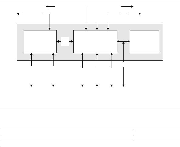
1.6 Intel® 850 Chipset
The Intel 850 chipset consists of the following devices:
∙82850 Memory Controller Hub (MCH) with Accelerated Hub Architecture (AHA) bus
∙82801BA I/O Controller Hub (ICH2) with AHA bus
∙SST 49LF004A Firmware Hub (FWH)
The MCH is a centralized controller for the system bus, the memory bus, the AGP bus, and the Accelerated Hub Architecture interface. The ICH2 is a centralized controller for the board’s I/O paths. The FWH provides the nonvolatile storage of the BIOS. The component combination provides the chipset interfaces as shown in Figure 3.
ATA-33/66/100 |
|
|
|
Network |
|
|
System Bus |
|
|
USB |
|
|
850 Chipset |
|
|
|
82850 |
AHA |
82801BA |
SST 49LF004A |
|
Memory Controller |
I/O Controller Hub |
Firmware Hub |
||
Bus |
||||
Hub (MCH) |
(ICH2) |
(FWH) |
||
|
LPC Bus
Dual RAMBUS |
|
AGP |
|
|
|
|
|
|
|
|
|
||
|
SMBus |
|
PCI Bus |
|
AC Link |
||||||||
Channels |
|
Interface |
|
|
|
||||||||
|
|
|
|
|
|
|
|
|
|
||||
|
|
|
|
|
|
|
|
|
|||||
|
|
|
|
|
|
|
|
|
|
|
|
|
|
|
|
|
|
|
|
|
|
|
|
|
|
|
|
OM11732
Figure 3. Intel 850 Chipset Block Diagram
For information about
The Intel 850 chipset
The SST 49LF004A Firmware Hub
Chipset resources
Refer to
http://developer.intel.com
http://www.ssti.com
Section 1.3, page 16
22

Product Description
1.6.1AGP
NOTE
The AGP connector is keyed for 1.5 V AGP cards only. Do not attempt to install a legacy 3.3 V AGP card. The AGP connector is not mechanically compatible with legacy 3.3 V AGP cards.
The AGP connector supports AGP add-in cards with 1.5 V Switching Voltage Level (SVL). An AGP Pro50 interface is available (for a 50 W maximum power draw) as a manufacturing option. Legacy 3.3 V AGP cards are not supported and will prevent the system from booting if installed.
For information about
The location of the AGP connector
The signal names of the AGP connector
Refer to
Figure 1, page 14
Table 40, page 62
AGP is a high-performance interface for graphics-intensive applications, such as 3D applications. While based on the PCI Local Bus Specification, Rev. 2.1, AGP is independent of the PCI bus and is intended for exclusive use with graphical display devices. AGP overcomes certain limitations of the PCI bus related to handling large amounts of graphics data with the following features:
∙Pipelined memory read and write operations that hide memory access latency
∙Demultiplexing of address and data on the bus for nearly 100 percent efficiency
For information about |
Refer to |
Obtaining the Accelerated Graphics Port Interface Specification |
Section 1.3, page 16 |
|
|
1.6.2USB
The ICH2 contains two separate USB controllers supporting four USB ports. One USB peripheral can be connected to each port. For more than four USB devices, an external hub can be connected to any of the ports. Two of the USB ports are implemented with stacked back panel connectors.
The other two are accessible via the front panel USB connector at location J9C1. One of the front panel USB connectors can be routed to the optional CNR connector. The D850GB board fully supports UHCI and uses UHCI-compatible software drivers.
NOTE
Computer systems that have an unshielded cable attached to a USB port may not meet FCC
Class B requirements, even if no device is attached to the cable. Use shielded cable that meets the requirements for full-speed devices.
For information about
The location of the USB connectors on the back panel
The signal names of the back panel USB connectors
The location of the front panel USB connector
The signal names of the front panel USB connector
The USB specification and UHCI
Refer to
Figure 8, page 50
Table 18, page 51
Figure 12, page 65
Table 44, page 66
Section 1.3, page 16
23
Intel Desktop Board D850GB Technical Product Specification
1.6.3IDE Support
1.6.3.1IDE Interfaces
The ICH2’s IDE controller has two independent bus-mastering IDE interfaces that can be independently enabled. The IDE interfaces support the following modes:
∙Programmed I/O (PIO): processor controls data transfer.
∙8237-style DMA: DMA offloads the processor, supporting transfer rates of up to 16 MB/sec.
∙Ultra DMA: DMA protocol on IDE bus supporting host and target throttling and transfer rates of up to 33 MB/sec.
∙ATA-66: DMA protocol on IDE bus supporting host and target throttling and transfer rates of up to 66 MB/sec. ATA-66 protocol is similar to Ultra DMA and is device driver compatible.
∙ATA-100: DMA protocol on IDE bus allows host and target throttling. The ICH2’s ATA-100 logic can achieve read transfer rates up to 100 MB/sec and write transfer rates up to
88 MB/sec.
NOTE
ATA-66 and ATA-100 are faster timings and require a specialized cable to reduce reflections, noise, and inductive coupling.
The IDE interfaces also support ATAPI devices (such as CD-ROM drives) and ATA devices using the transfer modes listed in Section 4.4.3.1 on page 98.
The BIOS supports Logical Block Addressing (LBA) and Extended Cylinder Head Sector (ECHS) translation modes. The drive reports the transfer rate and translation mode to the BIOS.
The D850GB board supports Laser Servo (LS-120) diskette technology through its IDE interfaces. An LS-120 drive can be configured as a boot device by setting the BIOS Setup program’s Boot menu to one of the following:
∙ARMD-FDD (ATAPI removable media device – floppy disk drive)
∙ARMD-HDD (ATAPI removable media device – hard disk drive)
For information about
The location of the IDE connectors
The signal names of the IDE connectors
BIOS Setup program’s Boot menu
Refer to
Figure 11, page 59
Table 41, page 63
Table 73, page 105
24

Product Description
1.6.3.2SCSI Hard Drive Activity LED Connector
The SCSI hard drive activity LED connector is a 1 x 2-pin connector that allows an add-in SCSI controller to use the same LED as the onboard IDE controller. For proper operation, this connector should be wired to the LED output of the add-in SCSI controller. The LED indicates
when data is being read from, or written to, both the add-in SCSI controller and the IDE controller.
For information about
The location of the SCSI hard drive activity LED connector
The signal names of the SCSI hard drive activity LED connector
Refer to
Figure 12, page 65
Table 43, page 66
1.6.4Real-Time Clock, CMOS SRAM, and Battery
The real-time clock provides a time-of-day clock and a multicentury calendar with alarm features. The real-time clock supports 256 bytes of battery-backed CMOS SRAM in two banks that are reserved for BIOS use.
A coin-cell battery (CR2032) powers the real-time clock and CMOS memory. When the computer is not plugged into a wall socket, the battery has an estimated life of three years. When the computer is plugged in, the standby current from the power supply extends the life of the battery. The clock is accurate to ± 13 minutes/year at 25 ºC with 3.3 VSB applied.
The time, date, and CMOS values can be specified in the BIOS Setup program. The CMOS values can be returned to their defaults by using the BIOS Setup program.
NOTE
If the battery and AC power fail, custom defaults, if previously saved, will be loaded into CMOS RAM at power-on.
For information about |
Refer to |
Proper date access in systems with D850GB boards |
Section 1.2, page 16 |
|
|
1.6.5SST 49LF004A 4 Mbit Firmware Hub (FWH)
The FWH provides the following:
∙System BIOS program
∙System security and manageability logic that enables protection for storing and updating of platform information
25
Intel Desktop Board D850GB Technical Product Specification
1.7 I/O Controller
The SMSC LPC47M102 I/O controller provides the following features:
∙3.3 V operation
∙One serial port
∙One parallel port with Extended Capabilities Port (ECP) and Enhanced Parallel Port (EPP) support
∙Serial IRQ interface compatible with serialized IRQ support for PCI systems
∙PS/2-style mouse and keyboard interfaces
∙Interface for one 1.2 MB or 1.44 MB diskette drive
∙Intelligent power management, including a programmable wake up event interface
∙PCI power management support
∙One fan tachometer input
The BIOS Setup program provides configuration options for the I/O controller.
For information about |
Refer to |
SMSC LPC47M102 I/O controller |
http://www.smsc.com |
|
|
1.7.1Serial Port
The D850GB board has one serial port connector on the back panel. The serial port’s NS16C550compatible UART supports data transfers at speeds up to 115.2 kbits/sec with BIOS support. The serial port can be assigned as COM1 (3F8h), COM2 (2F8h), COM3 (3E8h), or COM4 (2E8h).
For information about
The location of the serial port connector
The signal names of the serial port connector
Refer to
Figure 8, page 50
Table 20, page 52
1.7.2Parallel Port
The 25-pin D-Sub parallel port connector located on the back panel. In the BIOS Setup program, the parallel port can be set to the following modes:
∙Output only (PC AT†-compatible mode)
∙Bi-directional (PS/2 compatible)
∙EPP
∙ECP
For information about
The location of the parallel port connector
The signal names of the parallel port connector
Setting the parallel port’s mode
Refer to
Figure 8, page 50
Table 19, page 51
Table 65, page 95
26

Product Description
1.7.3Diskette Drive Controller
The I/O controller supports one diskette drive that is compatible with the 82077 diskette drive controller and supports both PC-AT and PS/2 modes.
For information about
The location of the diskette drive connector
The signal names of the diskette drive connector
The supported diskette drive capacities and sizes
Refer to
Figure 11, page 59
Table 42, page 64
Table 68, page 100
1.7.4Keyboard and Mouse Interface
PS/2 keyboard and mouse connectors are located on the back panel. The +5 V lines to these connectors are protected with a PolySwitch† circuit that, like a self-healing fuse, reestablishes the connection after an overcurrent condition is removed.
NOTE
The keyboard is supported in the bottom PS/2 connector and the mouse is supported in the top PS/2 connector. Power to the computer should be turned off before a keyboard or mouse is connected or disconnected.
The keyboard controller contains the AMI keyboard and mouse controller code, provides the keyboard and mouse control functions, and supports password protection for power-on/reset. A power-on/reset password can be specified in the BIOS Setup program.
For information about
The location of the keyboard and mouse connectors
The signal names of the keyboard and mouse connectors
Refer to
Figure 8, page 50
Table 17, page 51
27
Intel Desktop Board D850GB Technical Product Specification
1.8 Audio Subsystem (Optional)
CAUTION
The pins on both the legacy-style 2-mm and the ATAPI CD-ROM connectors are wired to the same inputs on the audio mixer. Do not attach CD-ROM drives to both connectors, otherwise, the board or drives could be damaged.
The audio subsystem includes these features:
·Split digital/analog architecture for improved S/N (signal-to-noise) ratio: ³ 85 dB
·Power management support for APM 1.2 and ACPI 1.0 (driver dependant)
·3-D stereo enhancement
Even though all connectors may not appear on all boards, the audio subsystem supports the following audio interfaces:
·CD-ROM (legacy-style 2-mm connector)
·ATAPI-style connectors:
¾CD-ROM
¾Auxiliary line in
·Back panel audio connectors:
¾Line out
¾Line in
¾Mic in
The audio subsystem consists of the following devices:
·Intel 82801BA I/O Controller Hub (ICH2)
·Analog Devices AD1881/AD1885 analog codec
Figure 4 is a block diagram of the audio subsystem.
|
|
|
|
|
|
|
|
|
|
|
|
|
|
|
|
|
|
|
|
|
|
|
|
|
|
82801BA |
|
|
|
|
|
Analog Devices |
|
|
|
CD-ROM |
|
|
|
||||||||
|
|
|
|
|
|
|
|
|
|
|
|
||||||||||||
|
|
|
|
|
|
|
|
|
|
|
|
|
Line In |
|
|
|
|
|
|||||
|
|
|
|
|
|
|
|
|
|
|
|
|
|
|
|||||||||
|
|
|
|
AC ’97 |
|
|
|
|
|
|
|
|
|
|
|
|
|
|
|||||
|
|
I/O Controller Hub |
|
|
|
AD1881/AD1885 |
|
|
|
|
|
Audio In |
|
|
|
|
|
||||||
|
|
|
|
Link |
|
|
|
|
|
|
|
|
|
|
|
||||||||
|
|
(ICH2) |
|
|
|
Analog Codec |
|
|
|
|
|
|
|
Mic In |
|
|
|
|
|
|
|
||
|
|
|
|
|
|
|
|
|
|
|
|
|
|
|
|
||||||||
|
|
|
|
|
|
|
|
|
|
|
|
|
|
|
|
|
|
||||||
|
|
|
|
|
|
|
|
|
|
|
|
|
|
|
|
|
|
|
|
|
|||
|
|
|
|
|
|
|
|
|
|
|
|
|
|
|
Line Out |
|
|
|
|||||
|
|
|
|
|
|
|
|
|
|
|
|
|
|
|
|
|
|
|
|
|
|
|
|
|
|
|
|
|
|
|
|
|
|
|
|
|
|
|
|
|
|
|
|
|
|
|
|
|
|
|
|
|
|
|
|
|
|
|
|
|
|
|
|
OM11733 |
|||||||
|
|
|
|
|
|
|
|
|
|
|
|
|
|
|
|
||||||||
|
|
|
|
||||||||||||||||||||
|
|
Figure 4. Audio Subsystem Block Diagram |
|||||||||||||||||||||
|
For information about |
|
|
|
|
|
|
|
|
Refer to |
|||||||||||||
|
|
|
|
|
|
|
|
|
|
|
|||||||||||||
|
The back panel audio connectors |
|
|
|
|
|
|
|
|
Section 2.8.1, page 50 |
|||||||||||||
|
|
|
|
|
|
|
|
|
|
|
|
|
|
|
|
|
|
|
|
|
|
|
|
28

Product Description
1.8.1Audio Connectors
1.8.1.1CD-ROM (Legacy-style 2-mm) Audio Connector (Optional)
A 1 x 4-pin legacy-style 2-mm connector connects an internal CD-ROM drive to the audio mixer.
For information about
The location of the legacy-style 2-mm connector
The signal names of the legacy-style 2-mm connector
Refer to
Figure 9, page 54
Table 38, page 57
1.8.1.2ATAPI CD-ROM Audio Connector (Optional)
A 1 x 4-pin ATAPI-style connector connects an internal ATAPI CD-ROM drive to the audio mixer.
For information about
The location of the ATAPI CD-ROM connector
The signal names of the ATAPI CD-ROM connector
Refer to
Figure 9, page 54
Table 26, page 55
1.8.1.3Auxiliary Line In Connector (Optional)
A 1 x 4-pin ATAPI-style connector connects the left and right channel signals of an internal audio device to the audio subsystem.
For information about
The location of the auxiliary line in connector
The signal names of the auxiliary line in connector
Refer to
Figure 9, page 54
Table 25, page 55
1.8.2Audio Subsystem Software
Audio software and drivers are available from Intel’s World Wide Web site.
For information about |
Refer to |
Obtaining audio software and drivers |
Section 1.2, page 16 |
|
|
29

Intel Desktop Board D850GB Technical Product Specification
1.9 LAN Subsystem
The Network Interface Controller subsystem consists of the ICH2 (with integrated LAN Media Access Controller) and a physical layer interface device. Features of the LAN subsystem include:
·PCI Bus Master interface
·CSMA/CD Protocol Engine
·Serial CSMA/CD unit interface that supports the following physical layer interface devices:
¾82562EM onboard LAN
¾82562ET/EM (10/100 Mbit/sec Ethernet) on CNR bus
¾82562EH (1 Mbit/sec HomePNA†) on CNR bus
·PCI Power Management
¾Supports APM
¾Supports ACPI technology
¾Supports Wake up from suspend state (Wake on LAN† technology)
1.9.1Intel® 82562EM Platform LAN Connect Device (Optional)
The Intel 82562EM component provides an interface to the back panel RJ-45 connector with integrated LEDs. This physical interface may alternately be provided through the CNR connector.
The Intel 82562EM provides the following functions:
·Basic 10/100 Ethernet LAN connectivity
·Supports RJ-45 connector with status indicator LEDs on the back panel
·Full device driver compatibility
·Advanced Power Management and ACPI support
·Programmable transit threshold
·Configuration EEPROM that contains the MAC address
·Remote monitoring (alerting)
1.9.2RJ-45 LAN Connector with Integrated LEDs (Optional)
Two LEDs are built into the RJ-45 LAN connector. Table 6 describes the LED states when the board is powered up and the LAN subsystem is operating.
Table 6. |
LAN Connector LED States |
||
|
|
|
|
LED Color |
|
LED State |
Condition |
Green |
|
Off |
10 Mbit/sec data rate is selected. |
|
|
On |
100 Mbit/sec data rate is selected. |
Yellow |
|
Off |
LAN link is not established. |
|
|
On (steady state) |
LAN link is established. |
|
|
On (brighter and pulsing) |
The computer is communicating with another computer on |
|
|
|
the LAN. |
30
Loading...