


 Loading...
Intel® Desktop Board DG43GT
Product Guide
Order Number: E68221-001

Revision History
Revision |
Revision History |
Date |
-001 |
First release of the Intel® Desktop Board DG43GT Product Guide |
June 2009 |
If an FCC declaration of conformity marking is present on the board, the following statement applies:
FCC Declaration of Conformity
This device complies with Part 15 of the FCC Rules. Operation is subject to the following two conditions:
(1) this device may not cause harmful interference, and (2) this device must accept any interference received, including interference that may cause undesired operation.
For questions related to the EMC performance of this product, contact:
Intel Corporation, 5200 N.E. Elam Young Parkway, Hillsboro, OR 97124 1-800-628-8686
This equipment has been tested and found to comply with the limits for a Class B digital device, pursuant to Part 15 of the FCC Rules. These limits are designed to provide reasonable protection against harmful interference in a residential installation. This equipment generates, uses, and can radiate radio frequency energy and, if not installed and used in accordance with the instructions, may cause harmful interference to radio communications. However, there is no guarantee that interference will not occur in a particular installation. If this equipment does cause harmful interference to radio or television reception, which can be determined by turning the equipment off and on, the user is encouraged to try to correct the interference by one or more of the following measures:
•Reorient or relocate the receiving antenna.
•Increase the separation between the equipment and the receiver.
•Connect the equipment to an outlet on a circuit other than the one to which the receiver is connected.
•Consult the dealer or an experienced radio/TV technician for help.
Any changes or modifications to the equipment not expressly approved by Intel Corporation could void the user’s authority to operate the equipment.
Tested to comply with FCC standards for home or office use.
Canadian Department of Communications Compliance Statement
This digital apparatus does not exceed the Class B limits for radio noise emissions from digital apparatus set out in the Radio Interference Regulations of the Canadian Department of Communications.
Le présent appareil numerique német pas de bruits radioélectriques dépassant les limites applicables aux appareils numériques de la classe B prescrites dans le Réglement sur le broullage radioélectrique édicté par le ministére des Communications du Canada.
Disclaimer
INFORMATION IN THIS DOCUMENT IS PROVIDED IN CONNECTION WITH INTEL® PRODUCTS. NO LICENSE, EXPRESS OR IMPLIED, BY ESTOPPEL OR OTHERWISE, TO ANY INTELLECTUAL PROPERTY RIGHTS IS GRANTED BY THIS DOCUMENT. EXCEPT AS PROVIDED IN INTEL’S TERMS AND CONDITIONS OF SALE FOR SUCH PRODUCTS, INTEL ASSUMES NO LIABILITY WHATSOEVER, AND INTEL DISCLAIMS ANY EXPRESS OR IMPLIED WARRANTY, RELATING TO SALE AND/OR USE OF INTEL PRODUCTS INCLUDING LIABILITY OR WARRANTIES RELATING TO FITNESS FOR A PARTICULAR PURPOSE, MERCHANTABILITY, OR INFRINGEMENT OF ANY PATENT, COPYRIGHT OR OTHER INTELLECTUAL PROPERTY RIGHT. Intel products are not intended for use in medical, life saving, or life sustaining applications. Intel may make changes to specifications and product descriptions at any time, without notice.
Intel Desktop Board DG43GT may contain design defects or errors known as errata which may cause the product to deviate from published specifications. Current characterized errata are available on request.
Contact your local Intel sales office or your distributor to obtain the latest specifications and before placing your product order.
Copies of documents which have an ordering number and are referenced in this document, or other Intel literature, may be obtained from Intel Corporation by going to the World Wide Web site at: http://intel.com/ or by calling 1-800-548-4725.
Intel, the Intel logo, and Intel Viiv are trademarks of Intel Corporation in the U.S. and other countries. * Other names and brands may be claimed as the property of others.
Copyright © 2009, Intel Corporation. All rights reserved.

Preface
This Product Guide gives information about board layout, component installation, BIOS update, and regulatory requirements for Intel® Desktop Board DG43GT.
Intended Audience
The Product Guide is intended for technically qualified personnel. It is not intended for general audiences.
Use Only for Intended Applications
All Intel Desktop Boards are evaluated as Information Technology Equipment (I.T.E.) for use in personal computers (PC) for installation in homes, offices, schools, computer rooms, and similar locations. The suitability of this product for other PC or embedded non-PC applications or other environments, such as medical, industrial, alarm systems, test equipment, etc. may not be supported without further evaluation by Intel.
Document Organization
The chapters in this Product Guide are arranged as follows:
1Desktop Board Features: a summary of product features
2Installing and Replacing Desktop Board Components: instructions on how to install the Desktop Board and other hardware components
3Updating the BIOS: instructions on how to update the BIOS
AError Messages and Indicators: information about BIOS error messages and beep codes
BRegulatory Compliance: safety standards, regulations, and product certifications
Conventions
The following conventions are used in this manual:
 CAUTION
Cautions warn the user about how to prevent damage to hardware or loss of data.
 NOTE
NOTE
Notes call attention to important information.
iii
Intel Desktop Board DG43GT Product Guide
Terminology
The table below gives descriptions of some common terms used in the product guide.
Term |
Description |
|
|
GB |
Gigabyte (1,073,741,824 bytes) |
|
|
GHz |
Gigahertz (one billion hertz) |
|
|
KB |
Kilobyte (1024 bytes) |
|
|
kHz |
Kilohertz (one thousand hertz) |
|
|
MB |
Megabyte (1,048,576 bytes) |
|
|
Mb |
Megabit (1,048,576 bits) |
|
|
MHz |
Megahertz (one million hertz) |
|
|
iv

Contents
1 |
Desktop Board Features |
|
|
Desktop Board Components................................................................................. |
11 |
|
Online Support .................................................................................................. |
13 |
|
Processor.......................................................................................................... |
13 |
|
Main Memory..................................................................................................... |
14 |
|
Intel® G43 Express Chipset ................................................................................. |
15 |
|
Intel G43 Graphics Subsystem...................................................................... |
15 |
|
Intel GMA X4500 Graphics Controller ..................................................... |
15 |
|
External PCI Express x16 Graphics......................................................... |
16 |
|
Audio Subsystem ............................................................................................... |
17 |
|
Legacy Input/Output (I/O) Controller .................................................................... |
18 |
|
LAN Subsystem ................................................................................................. |
18 |
|
Hi-Speed USB 2.0 Support .................................................................................. |
19 |
|
ATA Support...................................................................................................... |
19 |
|
PATA Interface ........................................................................................... |
19 |
|
SATA Interfaces ......................................................................................... |
20 |
|
Expandability..................................................................................................... |
20 |
|
BIOS................................................................................................................ |
21 |
|
ATA Auto Configuration ............................................................................... |
21 |
|
PCI and PCI Express* Auto Configuration ....................................................... |
21 |
|
Security Passwords..................................................................................... |
21 |
|
Hardware Management Features .......................................................................... |
22 |
|
Fan Speed, Thermal, and Voltage Monitoring and Control ................................. |
22 |
|
Chassis Intrusion........................................................................................ |
22 |
|
Power Management Features ............................................................................... |
23 |
|
ACPI......................................................................................................... |
23 |
|
Hardware Support ...................................................................................... |
23 |
|
Power Connectors ............................................................................... |
23 |
|
Fan Headers ....................................................................................... |
24 |
|
LAN Wake Capabilities.......................................................................... |
24 |
|
Instantly Available PC Technology.......................................................... |
24 |
|
+5 V Standby Power Indicator............................................................... |
25 |
|
Wake from USB .................................................................................. |
25 |
|
Wake from Serial ................................................................................ |
25 |
|
PME# Signal Wake-up Support.............................................................. |
25 |
|
WAKE# Signal Wake-up Support ........................................................... |
26 |
|
Wake from PS/2.................................................................................. |
26 |
|
ENERGY STAR*, e-Standby, and EuP Compliance ............................................ |
26 |
|
Speaker............................................................................................................ |
26 |
|
Battery............................................................................................................. |
26 |
|
Real-Time Clock................................................................................................. |
26 |
2 |
Installing and Replacing Desktop Board Components |
|
|
Before You Begin ............................................................................................... |
27 |
|
Installation Precautions....................................................................................... |
28 |
|
Prevent Power Supply Overload .................................................................... |
28 |
|
Observe Safety and Regulatory Requirements................................................. |
28 |
v
Intel Desktop Board DG43GT Product Guide |
|
|
|
Installing the I/O Shield ...................................................................................... |
29 |
|
Installing and Removing the Desktop Board ........................................................... |
30 |
|
Installing and Removing a Processor..................................................................... |
31 |
|
Installing a Processor .................................................................................. |
31 |
|
Installing a Processor Fan Heat Sink.............................................................. |
34 |
|
Connecting the Processor Fan Heat Sink Cable................................................ |
35 |
|
Removing the Processor .............................................................................. |
35 |
|
Installing and Removing Memory.......................................................................... |
36 |
|
Guidelines for Dual Channel Memory Configuration.......................................... |
36 |
|
Two or Four DIMMs ............................................................................. |
36 |
|
Three DIMMs ...................................................................................... |
37 |
|
Installing DIMMs ........................................................................................ |
38 |
|
Removing DIMMs........................................................................................ |
40 |
|
Installing and Removing a PCI Express x16 Card .................................................... |
41 |
|
Installing a PCI Express x16 Card ................................................................. |
41 |
|
Removing the PCI Express x16 Card.............................................................. |
42 |
|
Connecting a PATA (IDE) Cable ............................................................................ |
43 |
|
Connecting Serial ATA (SATA) Cables.................................................................... |
45 |
|
Connecting to Internal Headers............................................................................ |
46 |
|
S/PDIF Header ........................................................................................... |
47 |
|
Front Panel HD Audio Header ....................................................................... |
47 |
|
Serial Port Header ...................................................................................... |
48 |
|
Parallel Port Header .................................................................................... |
48 |
|
IEEE 1394a Header..................................................................................... |
49 |
|
Front Panel Header ..................................................................................... |
49 |
|
Alternate Front Panel Power LED Header ........................................................ |
50 |
|
USB 2.0 Headers ........................................................................................ |
50 |
|
Chassis Intrusion Header ............................................................................. |
51 |
|
Connecting to the Audio System........................................................................... |
51 |
|
Connecting Chassis Fan and Power Supply Cables................................................... |
52 |
|
Chassis Fan Cables ..................................................................................... |
52 |
|
Power Supply Cables................................................................................... |
53 |
|
Setting the BIOS Configuration Jumper ................................................................. |
54 |
|
Clearing Passwords in the BIOS Setup Program ...................................................... |
55 |
|
Clearing CMOS Memory ...................................................................................... |
56 |
|
Replacing the Battery ......................................................................................... |
57 |
3 |
Updating the BIOS |
|
|
Updating the BIOS with the Intel® Express BIOS Update Utility................................. |
63 |
|
Updating the BIOS with the ISO Image BIOS Update File or the Iflash Memory |
|
|
Update Utility............................................................................................... |
64 |
|
Obtaining the BIOS Update File .................................................................... |
64 |
|
Updating the BIOS with the ISO Image BIOS Update File ................................. |
64 |
|
Updating the BIOS with the Iflash Memory Update Utility ................................. |
65 |
|
Recovering the BIOS................................................................................... |
66 |
A |
Error Messages and Indicators |
|
|
BIOS Beep Codes............................................................................................... |
67 |
|
BIOS Error Messages .......................................................................................... |
67 |
vi
|
|
Contents |
B Regulatory Compliance |
|
|
Safety Standards ............................................................................................... |
69 |
|
|
Place Battery Marking ................................................................................. |
69 |
European Union Declaration of Conformity Statement.............................................. |
70 |
|
Product Ecology Statements ................................................................................ |
71 |
|
|
Recycling Considerations ............................................................................. |
71 |
|
Lead-free 2LI/Pb-free 2LI Board ................................................................... |
74 |
|
Restriction of Hazardous Substances (RoHS) .................................................. |
75 |
|
EU RoHS ............................................................................................ |
75 |
|
China RoHS ........................................................................................ |
76 |
EMC Regulations ................................................................................................ |
78 |
|
|
Ensure Electromagnetic Compatibility (EMC) Compliance.................................. |
79 |
Product Certifications.......................................................................................... |
80 |
|
|
Board-Level Certification Markings ................................................................ |
80 |
|
Chassis and Component Certifications............................................................ |
81 |
Figures |
|
|
1. |
Intel Desktop Board DG43GT Components ....................................................... |
11 |
2. |
LAN Status LEDs .......................................................................................... |
18 |
3. |
Location of the +5 V Standby Power Indicator .................................................. |
25 |
4. |
Installing the I/O Shield ................................................................................ |
29 |
5. |
Intel Desktop Board DG43GT Mounting Screw Hole Locations.............................. |
30 |
6. |
Lift the Socket Lever ..................................................................................... |
31 |
7. |
Lift the Load Plate......................................................................................... |
32 |
8. |
Remove the Protective Socket Cover ............................................................... |
32 |
9. |
Remove the Processor from the Protective Processor Cover ................................ |
33 |
10. |
Install the Processor ..................................................................................... |
33 |
11. |
Close the Load Plate ..................................................................................... |
34 |
12. |
Connecting the Processor Fan Heat Sink Cable.................................................. |
35 |
13. |
Dual Channel Memory Configuration with Two DIMMs ........................................ |
36 |
14. |
Dual Channel Memory Configuration with Four DIMMs........................................ |
37 |
15. |
Dual Channel Memory Configuration with Three DIMMs ...................................... |
37 |
16. |
Use DDR2 DIMMs ......................................................................................... |
38 |
17. |
Installing a DIMM ......................................................................................... |
39 |
18. |
Installing a PCI Express x16 Card ................................................................... |
41 |
19. |
Removing a PCI Express x16 Card .................................................................. |
42 |
20. |
Connecting the IDE Cable .............................................................................. |
44 |
21. |
Connecting a Serial ATA Cable........................................................................ |
45 |
22. |
Internal Headers .......................................................................................... |
46 |
23. |
Back Panel Audio Connectors ......................................................................... |
51 |
24. |
Location of the Chassis Fan Headers................................................................ |
52 |
25. |
Connecting Power Supply Cables .................................................................... |
53 |
26. |
Location of the BIOS Configuration Jumper Block .............................................. |
54 |
27. |
Location of the Clear CMOS Memory Jumper Block ............................................ |
57 |
28. |
Removing the Battery ................................................................................... |
62 |
29. |
Intel Desktop Board DG43GT China RoHS Material Self Declaration Table ............. |
77 |
vii
Intel Desktop Board DG43GT Product Guide |
|
|
Tables |
|
|
1. |
Feature Summary.......................................................................................... |
9 |
2. |
Intel Desktop Board DG43GT Components ....................................................... |
12 |
3. |
Back Panel and Front Panel Audio Jack Retasking Support .................................. |
17 |
4. |
LAN Connector LEDs ..................................................................................... |
19 |
5. |
S/PDIF Connector Signal Names ..................................................................... |
47 |
6. |
Front Panel Audio Signal Names for Intel HD Audio............................................ |
47 |
7. |
Front Panel Audio Header Signal Names for AC ’97 Audio ................................... |
47 |
8. |
Serial Port Header Signal Names..................................................................... |
48 |
9. |
Parallel Port Header ...................................................................................... |
48 |
10. |
IEEE 1394a Header Signal Names ................................................................... |
49 |
11. |
Front Panel Header Signal Names ................................................................... |
49 |
12. |
Alternate Front Panel Power LED Header Signal Names ...................................... |
50 |
13. |
USB 2.0 Header Signal Names........................................................................ |
50 |
14. |
Chassis Intrusion Header Signal Names ........................................................... |
51 |
15. |
Jumper Settings for the BIOS Setup Program Modes.......................................... |
55 |
16. |
Clear CMOS Jumper Settings.......................................................................... |
57 |
17. |
Beep Codes ................................................................................................. |
67 |
18. |
BIOS Error Messages .................................................................................... |
67 |
19. |
Safety Standards.......................................................................................... |
69 |
20. |
Lead-Free Second Level Interconnect Marks ..................................................... |
75 |
21. |
China RoHS Environmentally Friendly Use Period Mark ....................................... |
76 |
22. |
EMC Regulations........................................................................................... |
78 |
23. |
Product Certification Markings ........................................................................ |
80 |
viii

1 Desktop Board Features
This chapter briefly describes the features of Intel® Desktop Board DG43GT. Table 1 summarizes the major features of the board.
Table 1. Feature Summary
Form Factor |
microATX (243.84 millimeters [9.60 inches] x 243.84 millimeters |
||
|
[9.60 inches]) |
||
|
|
|
|
Processor |
Support for an Intel® processor in the LGA775 package |
||
Main Memory |
• |
Four 240-pin, DDR2 1.8 V SDRAM Dual Inline Memory Module |
|
|
|
(DIMM) sockets |
|
|
• |
800/667 MHz single or dual channel DDR2 SDRAM interface |
|
|
• |
Support for up to 16 GB of main memory |
|
|
|
|
|
Chipset |
• |
Intel® G43 Express Chipset consisting of: |
|
|
• |
Intel G43 Express Chipset Graphics and Memory Controller Hub |
|
|
|
(GMCH) |
|
|
• |
Intel® 82801JIB I/O Controller Hub (ICH10) |
|
Integrated Graphics |
• |
Intel G43 Express Chipset with Intel® Graphics Media Accelerator |
|
|
|
X4500 (Intel® GMA X4500) |
|
|
• |
Support for dual independent displays via HDMI* and DVI-I ports |
|
|
|
|
|
External Graphics |
• |
One PCI Express* 2.0 x16 connector |
|
|
• |
Two PCI Express 1.1 x1 connectors |
|
|
• |
One PCI* connector |
|
|
|
|
|
Audio |
Onboard subsystem, featuring: |
||
|
• |
Independent 8-channel (7.1) back panel audio streams |
|
|
• |
2-channel stereo front panel audio streams via an onboard header |
|
|
• |
Intel® High Definition Audio (Intel® HD Audio) interface |
|
|
• |
Realtek* ALC888S audio codec |
|
|
• |
Back panel optical S/PDIF output connector and an onboard 4-pin |
|
|
|
S/PDIF output header |
|
|
|
|
|
Expansion |
• |
One PCI Express 2.0 x16 connector |
|
Capabilities |
• |
Two PCI Express 1.1 x1 connectors |
|
|
• |
One PCI connector |
|
|
|
|
|
Legacy I/O Support |
Legacy I/O controller that provides: |
||
|
• |
One serial port via an onboard header |
|
|
• |
One parallel port via an onboard header |
|
|
• |
Back panel PS/2 keyboard port |
|
|
|
|
|
continued
9

Intel Desktop Board DG43GT Product Guide
Table 1. Feature Summary (continued)
Peripheral |
• |
Twelve USB 2.0 ports: |
|
Interfaces |
|
― Six ports routed to the back panel |
|
|
|
― Six ports routed to three front panelUSB headers |
|
|
• |
Two IEEE 1394a ports: |
|
|
|
― One port routed to the back panel |
|
|
|
― One port routed to an onboard header |
|
|
• |
Four Serial ATA (SATA) channels (3.0 Gb/s) via ICH10 |
|
|
• |
One dual-channel Parallel ATA (PATA) port via an onboard header |
|
BIOS |
• |
Intel® Platform Innovation Framework for EFI |
|
|
• |
32 Mb symmetrical flash memory device |
|
|
• |
Support for SMBIOS |
|
|
• |
Intel® Rapid BIOS Boot |
|
|
• |
Intel® Express BIOS Update |
|
Power Management |
• |
Support for Advanced Configuration and Power Interface (ACPI) |
|
|
• |
Suspend to RAM (STR) |
|
|
• |
Wake on USB, PCI Express, PCI, LAN, PS/2 front panel, and serial |
|
|
|
port |
|
|
• |
ENERGY STAR* capable |
|
|
|
|
|
Hardware |
Hardware monitor with: |
||
Management |
• |
Three fan sensing inputs used to monitor fan activity |
|
|
• |
Intel® Quiet System Technology (Intel® QST) fan speed control |
|
|
• |
Voltage sensing to detect out of range values |
|
|
|
|
|
LAN Support |
Intel® 82567V Gigabit (10/100/1000 Mb/s) Ethernet LAN controller |
||
Operating System |
• |
Microsoft Windows* 7 Ultimate |
|
Support |
• |
Microsoft Windows 7 Home Premium |
|
|
• |
Microsoft Windows 7 Basic |
|
|
• |
Microsoft Windows Vista* Ultimate |
|
|
• |
Microsoft Windows Vista Enterprise |
|
|
• |
Microsoft Windows Vista Business |
|
|
• |
Microsoft Windows Vista Home Premium |
|
|
• |
Microsoft Windows Vista Home Basic |
|
|
• |
Microsoft Windows Vista Ultimate 64-bit edition |
|
|
• |
Microsoft Windows Vista Enterprise 64-bit edition |
|
|
• |
Microsoft Windows Vista Business 64-bit edition |
|
|
• |
Microsoft Windows Vista Home Premium 64-bit edition |
|
|
• |
Microsoft Windows Vista Home Basic 64-bit edition |
|
|
• |
Microsoft Windows* XP Media Center Edition 2005 |
|
|
• |
Microsoft Windows XP Professional |
|
|
• |
Microsoft Windows XP Professional x64 Edition |
|
|
• |
Microsoft Windows XP Home |
|
|
|
|
|
For more information about Intel Desktop Board DG43GT, including the Technical Product Specification (TPS), BIOS updates, and device drivers, go to http://www.intel.com/products/motherboard/DG43GT/index.htm.
10

Desktop Board Features
Desktop Board Components
Figure 1 shows the approximate location of the major components on Intel Desktop Board DG43GT.
Figure 1. Intel Desktop Board DG43GT Components
11
Intel Desktop Board DG43GT Product Guide
Table 2. Intel Desktop Board DG43GT Components
Label |
Description |
|
|
A |
Front panel audio header |
|
|
B |
PCI bus connector |
|
|
C |
IEEE 1394a header |
|
|
D |
PCI Express x1 connector |
|
|
E |
PCI Express x16 connector |
|
|
F |
Battery |
|
|
G |
PCI Express x1 connector |
|
|
H |
Back panel connectors |
|
|
I |
12 V processor core voltage connector (2 x 2 pin) |
|
|
J |
Rear chassis fan header (3-pin) |
|
|
K |
Processor socket |
|
|
L |
Processor fan header (4-pin) |
|
|
M |
DDR2 DIMM 0 sockets |
|
|
N |
Front chassis fan header (3-pin) |
|
|
O |
DDR2 DIMM 1 sockets |
|
|
P |
Serial header |
|
|
Q |
Parallel port header |
|
|
R |
Main power connector (2 x 12 pin) |
|
|
S |
Front panel header |
|
|
T |
Serial ATA connectors (4) |
|
|
U |
Alternate front panel power LED header |
|
|
V |
High-speed USB 2.0 headers (3) |
|
|
W |
Parallel ATA connector |
|
|
X |
Clear CMOS jumper block |
|
|
Y |
Chassis intrusion header |
|
|
Z |
BIOS configuration jumper block |
|
|
AA |
Speaker |
|
|
BB |
S/PDIF header |
|
|
12
Desktop Board Features
Online Support
For more information on Intel Desktop Board DG43GT consult the following online resources:
• |
Intel Desktop Board DG43GT |
http://www.intel.com/products/motherboard/DG43GT/in |
|
|
dex.htm |
• |
Desktop Board support |
http://support.intel.com/support/motherboards/desktop |
|
|
/DG43GT |
• |
Available configurations for Intel |
http://www.intel.com/products/motherboard/DG43GT/in |
|
Desktop Board DG43GT |
dex.htm |
• |
Supported processors |
http://processormatch.intel.com |
• |
Chipset information |
http://www.intel.com/products/desktop/chipsets/index. |
|
|
htm |
• |
BIOS and driver updates |
http://downloadcenter.intel.com/ |
• |
Integration information |
http://www.intel.com/support/go/buildit |
Processor
 CAUTION
Failure to use an appropriate power supply and/or not connecting the 12 V (2 x 2 pin) power connector to the Desktop Board may result in damage to the board, or the system may not function properly.
Intel Desktop Board DG43GT supports an Intel processor in the LGA775 package. Processors are not included with the Desktop Board and must be purchased separately. The processor connects to the Desktop Board through the LGA775 socket. For instructions on installing or upgrading the processor, refer to page 31.
A list of supported processors for Intel Desktop Board DG43GT, can be found at http://processormatch.intel.com.
13

Intel Desktop Board DG43GT Product Guide
Main Memory
 NOTE
NOTE
To be fully compliant with all applicable Intel® SDRAM memory specifications, the board should be populated with DIMMs that support the Serial Presence Detect (SPD) data structure. If your memory modules do not support SPD, you will see a notification to this effect on the screen at power up. The BIOS will attempt to configure the memory controller for normal operation.
The Desktop Board supports the dual or single channel memory configurations defined below:
•Four 240-pin Double Data Rate 2 (DDR2) SDRAM Dual Inline Memory Module (DIMM) connectors with gold-plated contacts
•Support for:
Non-ECC, 1.8 V, DDR2 800/667 MHz memory
Serial Presence Detect (SPD) memory only
Unbuffered, non-registered singleor double-sided DIMMs (except double-sided DIMMs with x16 organization)
Memory configurations listed below:
•Up to 2 GB utilizing 256 Mb technology
•Up to 4 GB utilizing 512 Mb or 1 Gb technology
•Up to 8 GB utilizing 1 Gb technology
•Up tp 16 GB utilizing 2 Gb technology
•A minimum of 512 MB of total memory is required
 NOTE
NOTE
System resources and hardware (such as PCI Express devices) require physical memory address locations that can reduce available addressable system memory. This could result in a reduction of as much as 1 GB or more of physical addressable memory being available to the operating system and applications, depending on the system configuration and operating system.
Go to the following locations for more information about:
•SDRAM specifications, http://intel.com/technology/memory/
•Installing memory, page 36 in Chapter 2
•Tested memory, http://cmtlabs.com/mbsearch.asp
14
Desktop Board Features
Intel® G43 Express Chipset
The Intel G43 Express Chipset consists of the following devices:
•Intel G43 Express Chipset Graphics and Memory Controller Hub (GMCH) with Direct Media Interface (DMI)
•Intel 82801JIB I/O Controller Hub (ICH10) with DMI
The GMCH component provides interfaces to the processor, memory, PCI Express, and the DMI interconnect. The GMCH also provides integrated graphics capabilities supporting 3D, 2D, and display capabilities. ICH10 is a centralized controller for the board’s I/O paths.
For more information on the Intel G43 Express Chipset go to http://developer.intel.com/products/chipsets/
Intel G43 Graphics Subsystem
The Intel G43 Express Chipset provides two separate, mutually exclusive graphics options. Either the integrated Intel Graphics Media Accelerator X4500 (GMA X4500) graphics controller is used or a PCI Express x16 add-in card can be used.
Intel GMA X4500 Graphics Controller
The GMA X4500 graphics controller supports dual independent displays via HDMI and DVI-I connectors on the Desktop Board back panel. When a PCI Express Graphics (x16, x8, or x4) add-in card is installed on the Desktop Board, the Intel GMA X4500 graphics controller is disabled.
The Intel GMA X4500 graphics controller has the following features:
•Advanced graphics performance, including:
DirectX10.0* and OpenGL* 2.0 compliant
Shader Model 4.0 support
•Enhanced video playback support, including:
Intel® Clear Video Technology (for more information go to http://www.intel.com/technology/graphics/ctv.htm)
Support for playback of Blu-ray Disc* technology DVDs
Software DVD at 30 fps full screen
Dynamic Video Memory Technology (DVMT) 5.0
15
Intel Desktop Board DG43GT Product Guide
•Advanced display support, including:
DVI specification 1.0 compliant
Dual independent display support via the DVI-I and HDMI back panel connectors
High Definition Content Protection (HDCP) version 1.1 support
DDC2B compliant interface with Advanced Digital Display 2 card or Media Expansion Card (ADD2/MEC), support for TV-out/TV-in and DVI digital display connections
Support for all HD display resolutions including 720p, 1080i, and 1080p
Support for digital and analog displays up to 1920 x 1200 at 60 Hz refresh rate (WUXGA) and 2560 x 1600 at 60 Hz refresh (WQXGA), respectively; also supports 1920 x 1080 resolution for full High Definition video playback quality
DVI-I Support
The DVI-I port supports both digital and analog DVI displays. The maximum supported resolution is 2048 x 1536 at 75 Hz refresh rate (QXGA) for analog video and 1920 x 1200 at 60 Hz refresh rate (WUXGA) for digital video. DVI analog output from the DVI-I connector can be converted to VGA with a DVI-I to VGA adapter.
When a non-video PCI Express add-in card is installed in the PCI Express x16 connector on the Desktop Board, the digital output of the DVI-I port is disabled.
HDMI* Technology Support
The HDMI port supports standard, enhanced, or high-definition video, plus multichannel digital audio on a single cable. It is compatible with all ATSC and DVB HDTV standards and supports 8-channel digital audio. The HDMI port is compliant with the HDMI 1.3 specification.
When a non-video PCI Express add-in card is installed in the PCI Express x16 connector on the Desktop Board, the HDMI port is disabled.
External PCI Express x16 Graphics
The GMCH supports an add-in PCI Express discrete graphics card via the PCI Express 2.0 x16 connector as follows:
•Supports the PCI Express 1.1 frequency of 1.25 GHz resulting in 2.5 Gb/s each direction (500 MB/s total). The maximum theoretical bandwidth on the interface is 4 GB/s in each direction simultaneously, for an aggregate of 8 GB/s when operating in x16 mode.
•Supports the PCI Express 2.0 frequency of 2.5 GHz resulting in 5.0 Gb/s each direction (1000 MB/s total). The maximum theoretical bandwidth on the interface is 8 GB/s in each direction simultaneously, for an aggregate of 16 GB/s when operating in x16 mode.
For more information on PCI Express technology, go to http://pcisig.com.
16
Desktop Board Features
Audio Subsystem
The onboard audio subsystem consists of the following:
•Intel ICH10 I/O controller hub
•Realtek ALC888S 10-channel audio codec
•Front panel audio header with support for:
Intel® High Definition Audio
AC ’97 Audio
•Onboard 4-pin S/PDIF output header
•Back panel audio connectors including an optical S/PDIF output connector
The audio subsystem supports the following features:
•A signal-to-noise (S/N) ratio of 95 dB
•Independent multi-streaming 7.1 audio (using the back panel audio connectors) and stereo (using the front panel audio header)
Go to the following locations for more information about:
•Audio drivers and utilities http://support.intel.com/support/motherboards/desktop/
•Location of the onboard audio headers, Figure 22 on page 46
•The location and description of the back panel audio connectors, Figure 23 on page 51
Table 3 lists the supported functions for the front panel and back panel audio jacks.
Table 3. Back Panel and Front Panel Audio Jack Retasking Support
Jack |
Mic |
Headphones |
Front |
|
Line |
Side |
Rear |
Center/ |
Speaker |
|
In |
Surround |
Surround |
Subwoofer |
|||
|
|
|
|
|||||
|
|
|
|
|
|
|
|
|
|
|
|
|
Front Panel |
|
|
|
|
|
|
|
|
|
|
|
||
Green |
|
Default |
Control Panel |
|
|
|
|
|
|
|
|
|
|
|
|
|
|
Pink |
Default |
|
|
|
|
|
|
|
|
|
|
|
|
|
|
|
|
|
|
|
|
Back Panel |
|
|
|
|
|
|
|
|
|
|
|
|
|
Blue |
|
Control Panel |
|
|
Default |
Control Panel |
|
|
|
|
|
|
|
|
|
|
|
Green |
|
Control Panel |
Default |
|
|
|
|
|
|
|
|
|
|
|
|
|
|
Pink |
Default |
|
|
|
|
|
|
|
|
|
|
|
|
|
|
|
|
Black |
|
|
|
|
|
|
Default |
|
|
|
|
|
|
|
|
|
|
Orange |
|
|
|
|
|
|
|
Default |
|
|
|
|
|
|
|
|
|
17
Intel Desktop Board DG43GT Product Guide
Legacy Input/Output (I/O) Controller
The legacy I/O controller provides the following:
•One serial port interface via an onboard header
•One parallel port interface via an onboard header
•One PS/2 port for keyboard or mouse support
•Serial IRQ interface compatible with serialized IRQ support for PCI systems
•Intelligent power management, including a programmable wake up event interface
•PCI power management support
 NOTE
NOTE
The PS/2 port supports both keyboard and mouse, but not concurrently. Automatic PS/2 device detection will occur during boot and cannot be changed until the next system boot.
LAN Subsystem
The LAN subsystem includes:
•Intel® ICH10
•Intel 82567V Gigabit (10/100/1000 Mb/s) Ethernet LAN controller
•RJ-45 LAN connector with integrated status LEDs
The subsystem features:
•CSMA/CD protocol engine
•LAN connect interface between ICH10 and the controller
•PCI Express power management
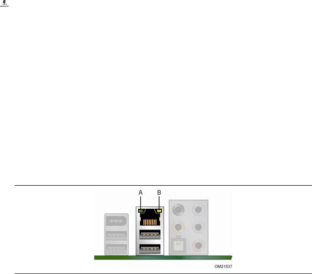
Two LEDs are built into the RJ-45 LAN connector located on the back panel (see Figure 2). These LEDs indicate the operating states of the LAN.
Figure 2. LAN Status LEDs
Table 4 describes the LED states when the board is powered up and the LAN subsystem is operating.
18
|
|
|
Desktop Board Features |
|
Table 4. LAN Connector LEDs |
|
|
||
|
|
|
|
|
LED |
LED Color |
LED State |
Indicates |
|
|
|
|
|
|
A (Link) |
Green |
Off |
LAN link is not established |
|
|
|
|
|
|
|
|
On |
LAN link is established |
|
|
|
|
|
|
|
|
Blinking |
LAN activity is occurring |
|
|
|
|
|
|
B (Speed) |
N/A |
Off |
10 Mb/s data rate |
|
|
|
|
|
|
|
Green |
On |
100 Mb/s data rate |
|
|
|
|
|
|
|
Yellow |
On |
1000 Mb/s data rate |
|
|
|
|
|
|
For information about LAN software and drivers go to
http://support.intel.com/support/motherboards/desktop
Hi-Speed USB 2.0 Support
The Desktop Board supports up to 12 USB 2.0 ports (six ports routed to the back panel and six ports routed to three internal headers) via ICH10. USB 2.0 ports are backward compatible with USB 1.1 devices. USB 1.1 devices will function normally at USB 1.1 speeds.
USB 2.0 support requires both an operating system and drivers that fully support USB 2.0 transfer rates. Disabling Hi-Speed USB in the BIOS reverts all USB 2.0 ports to USB 1.1 operation. This may be required to accommodate operating systems that do not support USB 2.0.
ATA Support
The board includes five ATA interface connectors:
•One PATA connector that supports two devices
•Four SATA connectors that support one device each
PATA Interface
The board’s discrete PATA controller provides one bus-mastering PATA interface that is accessible through a standard IDE connector The PATA interface supports the following modes:
•Programmed I/O (PIO): the processor controls data transfer.
•8237-style DMA: DMA offloads the processor, supporting transfer rates of up to 16 MB/s.
•Ultra DMA: DMA protocol on the ATA bus supporting host and target throttling and transfer rates of up to 33 MB/s.
•ATA-66: DMA protocol on the ATA bus supporting host and target throttling and transfer rates of up to 66 MB/s. ATA-66 protocol is similar to Ultra DMA and is device driver compatible.
•ATA-100: DMA protocol on the ATA bus allows host and target throttling.
19

Intel Desktop Board DG43GT Product Guide
 NOTE
NOTE
ATA-66 and ATA-100 are faster timings and require a specialized cable to reduce reflections, noise, and inductive coupling.
The PATA interface also supports ATAPI devices (such as CD-ROM drives) and ATA devices using the transfer modes.
The BIOS supports Logical Block Addressing (LBA) and Extended Cylinder Head Sector (ECHS) translation modes. The drive reports the transfer rate and translation mode to the BIOS.
SATA Interfaces
The ICH10 SATA controller provides four independent SATA ports with a theoretical maximum transfer rate of 3.0 Gb/s on each port. One device can be installed on each port for a maximum of four SATA devices. A point-to-point interface is used for host to device connections, unlike PATA which supports a master/slave configuration and two devices on each channel.
For compatibility, the underlying SATA functionality is transparent to the operating system. The SATA controller supports IDE and AHCI configuration and can operate in both legacy and native modes. In Legacy mode, standard ATA I/O and IRQ resources are assigned (IRQ 14 and 15). In Native mode, standard PCI Conventional bus resource steering is used. Native mode is the preferred mode for configurations using the Windows* XP and Windows Vista* operating systems.
Expandability
For system expansion, the Desktop Board provides the following expansion slots:
•One PCI Express 2.0 x16 connector (compatible with PCI Express 1.1 add-in cards)
•Two PCI Express 1.1 x1 connectors
•One PCI bus connector
20
Desktop Board Features
BIOS
The BIOS provides the Power-On Self-Test (POST), the BIOS Setup program, the PCI/PCI Express auto-configuration utilities, and the video BIOS. The BIOS is stored in the Serial Peripheral Interface (SPI) Flash device.
The BIOS can be updated by following the instructions in Chapter 3.
ATA Auto Configuration
If you install a Serial or Parallel ATA device in your computer, the auto-configuration utility in the BIOS automatically detects and configures the device for your computer. You do not need to run the BIOS Setup program after installing an ATA device. You can override the auto-configuration options by specifying manual configuration in the BIOS Setup program.
PCI and PCI Express* Auto Configuration
If you install a PCI/PCI Express add-in card in your computer, the PCI/PCI Express auto-configuration utility in the BIOS automatically detects and configures the resources (IRQs, DMA channels, and I/O space) for that add-in card. You do not need to run the BIOS Setup program after you install a PCI or PCI Express add-in card.
Security Passwords
The BIOS includes security features that restrict whether the BIOS Setup program can be accessed and who can boot the computer. A supervisor password and a user password can be set for the BIOS Setup and for booting the computer, with the following restrictions:
•The supervisor password gives unrestricted access to view and change all Setup options. If only the supervisor password is set, pressing <Enter> at the password prompt of Setup gives the user restricted access to Setup.
•If both the supervisor and user passwords are set, you must enter either the supervisor password or the user password to access Setup. Setup options are then available for viewing and changing depending on whether the supervisor or user password was entered.
•Setting a user password restricts who can boot the computer. The password prompt is displayed before the computer is booted. If only the supervisor password is set, the computer boots without asking for a password. If both passwords are set, you can enter either password to boot the computer.
For instructions on resetting the password, see “Clearing Passwords in the BIOS Setup Program” on page 55.
21
Intel Desktop Board DG43GT Product Guide
Hardware Management Features
The hardware management features of Intel Desktop Board DG43GT enable the board to be compatible with the Wired for Management (WfM) specification. The board has several hardware management features including the following:
•Fan speed monitoring and control
•Thermal and voltage monitoring
•Chassis intrusion detection
Fan Speed, Thermal, and Voltage Monitoring and Control
The board’s fan speed, thermal, and voltage monitoring and control features include the following:
•Monitoring of power supply voltages to detect levels above and below acceptable values
•Intel Quiet System Technology fan speed control, delivering acoustically-optimized thermal management
 NOTE
NOTE
Memory must be installed in the Channel A, DIMM 0 socket to enable Intel Quiet System Technology.
•Thermally monitored closed-loop fan control, for all onboard fans, that can adjust fan speed according to thermal conditions.
•Fan speed controllers and sensors integrated into the ICH10
•Thermal sensors in the processor, GMCH, and ICH10, plus an onboard remote sensor
 NOTE
NOTE
The minimum thermal reporting threshold for the GMCH is 66 °C. The GMCH thermal sensor will display 66 °C until the temperature rises above this point.
Chassis Intrusion
The board supports a chassis security feature that detects if the chassis cover has been removed. The security feature uses a mechanical switch on the chassis that can be connected to the chassis intrusion header on the Desktop Board. See Figure 22 for the location of the chassis intrusion header.
22
Desktop Board Features
Power Management Features
Power management is implemented at several levels, including:
•Software support through the Advanced Configuration and Power Interface (ACPI)
•Hardware support:
Power connectors
Fan headers
LAN wake capabilities
Instantly Available PC technology (Suspend to RAM)
+5 V standby power indicator LED
Wake from USB
Wake from serial
Power Management Event signal (PME#) wakeup support
WAKE# signal wake-up support
Wake from PS/2
•ENERGY STAR qualified
ACPI
ACPI gives the operating system direct control over the power management and Plug and Play functions of a computer. The use of ACPI with the Desktop Board requires an operating system that provides full ACPI support.
Hardware Support
Power Connectors
ATX12V-compliant power supplies can turn off the computer power through system control. When an ACPI-enabled computer receives the correct command, the power supply removes all non-standby voltages.
When resuming from an AC power failure, the computer returns to the power state it was in before power was interrupted (either on or off). The computer’s response can be set by using the Last Power State feature in the BIOS Setup program’s Boot menu.
The Desktop Board has two power connectors. See Figure 25 on page 53 for the location of the power connectors.
23
Intel Desktop Board DG43GT Product Guide
Fan Headers
The function/operation of the fans is as follows:
•The fans are on when the computer is in the ACPI S0 state.
•The fans are off when the computer is in the ACPI S3, S4, or S5 state.
•All fan headers support closed-loop fan control that can adjust the fan speed according to thermal conditions.
•All fan headers have a +12 V DC connection.
The Desktop Board has a 4-pin processor fan header and two 3-pin chassis fan headers.
LAN Wake Capabilities
 CAUTION
For LAN wake capabilities, the 5 V standby line for the power supply must be capable of delivering adequate +5 V standby current. Failure to provide adequate standby current when using this feature can damage the power supply.
LAN wakeup capabilities enable remote wake-up of the computer through a network. The LAN subsystem monitors network traffic and upon detecting a Magic Packet* frame, it asserts a wake-up signal that powers up the computer.
Instantly Available PC Technology
 CAUTIONS
For Instantly Available PC technology, the 5 V standby line for the power supply must be capable of delivering adequate +5 V standby current. Failure to provide adequate standby current when using this feature can damage the power supply and/or effect ACPI S3 sleep state functionality.
Power supplies used with this Desktop Board must be able to provide enough standby current to support the standard Instantly Available (ACPI S3 sleep state) configuration. If the standby current necessary to support multiple wake events from the PCI and/or USB buses exceeds power supply capacity, the Desktop Board may lose register settings stored in memory.
Instantly Available PC technology enables the board to enter the ACPI S3 (Suspend-to- RAM) sleep state. While in the S3 sleep state, the computer will appear to be off. If the computer has a dual-colored power LED on the front panel, the sleep state is indicated by the LED turning amber. When signaled by a wake-up device or event, the computer quickly returns to its last known awake state.
The Desktop Board supports the PCI Bus Power Management Interface Specification. Add-in cards that support this specification can participate in power management and can be used to wake the computer.
24
Desktop Board Features
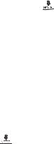
+5 V Standby Power Indicator
 CAUTION
If the AC power has been switched off and the standby power indicator is still lit, disconnect the power cord before installing or removing any devices connected to the board. Failure to do so could damage the board and any attached devices.
The Desktop Board’s standby power indicator, shown in Figure 3, is lit when there is standby power still present on the board even when the computer appears to be off. For example, when this green LED is lit, standby power is still present at the memory module sockets and the PCI/PCI Express bus connectors.
Figure 3. Location of the +5 V Standby Power Indicator
For more information on standby current requirements for the Desktop Board, refer to the Technical Product Specification at http://support.intel.com/support/motherboards/desktop/.
Wake from USB
 NOTE
NOTE
Wake from USB requires the use of a USB peripheral that supports Wake from USB.
USB bus activity wakes the computer from an ACPI S1 or S3 state.
Wake from Serial
Serial bus activity wakes the computer from an ACPI S1 or S3 state.
PME# Signal Wake-up Support
When the PME# signal on the PCI bus is asserted, the computer wakes from an ACPI S1, S3, S4, or S5 state.
25
Loading...