


Intel® NUC 9 Extreme/Pro Kit
Technical Product Specification
Revision 1.0
Regulatory Model: NUC9QN
December 2019
Intel® NUC 9 Extreme Kit NUC9i9QNX, NUC9i7QNX, NUC9i5QNX, Intel® NUC 9 Pro Kit NUC9VXQNX, or NUC9V7QNX may contain design defects or errors known as errata that may cause the product to deviate from published specifications. Current characterized errata, if any, are documented in this product specification

Revision History
Revision |
Revision History |
Date |
|
|
|
1.0 |
First release |
December 2019 |
|
|
|
|
|
|
|
|
|
|
|
|
Disclaimer
This product specification applies only to the standard Intel® NUC 9 Extreme/Pro Kits with BIOS identifier QXCFL579 or QNCFLX70.
INFORMATION IN THIS DOCUMENT IS PROVIDED IN CONNECTION WITH INTEL® PRODUCTS. NO LICENSE, EXPRESS OR IMPLIED, BY ESTOPPEL OR OTHERWISE, TO ANY INTELLECTUAL PROPERTY RIGHTS IS GRANTED BY THIS DOCUMENT. EXCEPT AS PROVIDED IN INTEL’S TERMS AND CONDITIONS OF SALE FOR SUCH PRODUCTS, INTEL ASSUMES NO LIABILITY WHATSOEVER, AND INTEL DISCLAIMS ANY EXPRESS OR IMPLIED WARRANTY, RELATING TO SALE AND/OR USE OF INTEL PRODUCTS INCLUDING LIABILITY OR WARRANTIES RELATING TO FITNESS FOR A PARTICULAR PURPOSE, MERCHANTABILITY, OR INFRINGEMENT OF ANY PATENT, COPYRIGHT OR OTHER INTELLECTUAL PROPERTY RIGHT. UNLESS OTHERWISE AGREED IN WRITING BY INTEL, THE INTEL PRODUCTS ARE NOT DESIGNED NOR INTENDED FOR ANY APPLICATION IN WHICH THE FAILURE OF THE INTEL PRODUCT COULD CREATE A SITUATION WHERE PERSONAL INJURY OR DEATH MAY OCCUR.
All Intel® NUC 9 Extreme/Pro Kits are evaluated as Information Technology Equipment (I.T.E.) for use in personal computers (PC) for installation in homes, offices, schools, computer rooms, and similar locations. The suitability of this product for other PC or embedded non-PC applications or other environments, such as medical, industrial, alarm systems, test equipment, etc. may not be supported without further evaluation by Intel.
Intel Corporation may have patents or pending patent applications, trademarks, copyrights, or other intellectual property rights that relate to the presented subject matter. The furnishing of documents and other materials and information does not provide any license, express or implied, by estoppel or otherwise, to any such patents, trademarks, copyrights, or other intellectual property rights.
Intel may make changes to specifications and product descriptions at any time, without notice.
Designers must not rely on the absence or characteristics of any features or instructions marked “reserved” or “undefined.” Intel reserves these for future definition and shall have no responsibility whatsoever for conflicts or incompatibilities arising from future changes to them.
Intel processor numbers are not a measure of performance. Processor numbers differentiate features within each processor family, not across different processor families: Go to:
Learn About Intel® Processor Numbers
Intel® NUC 9 Extreme/Pro Kits may contain design defects or errors known as errata, which may cause the product to deviate from published specifications. Current characterized errata are available on request.
Contact your local Intel sales office or your distributor to obtain the latest specifications before placing your product order.
Intel, the Intel logo and Intel Core are trademarks of Intel Corporation in the U.S. and/or other countries. * Other names and brands may be claimed as the property of others.
Copyright © 2019 Intel Corporation. All rights reserved.

Preface
This Product Specification specifies the layout, components, connectors, power and environmental features for the Intel® NUC 9 Extreme Kit NUC9i9QNX, NUC9i7QNX, NUC9i5QNX, Intel® NUC 9 Pro Kit NUC9VXQNX, and NUC9V7QNX.
NOTE |
In this document, the use of “Intel® NUC 9 Extreme Kit” will refer to the NUC9i9QNX, NUC9i7QNX, or NUC9i5QNX versions. The use of “Intel® NUC 9 Pro Kit” will refer to the NUC9VXQNX or NUC9V7QNX versions. When possible further consolidation of the naming convention will be used “NUC 9 Extreme/Pro Kit” when referring to shared features or capabilities. The usage of
“NUC 9 Extreme/Pro Compute Element” refers to the Intel® NUC Element product contained inside the NUC 9 Extreme/Pro Kit.
Intended Audience
This document is intended to provide technical information about Intel® NUC 9 Extreme Kit NUC9i9QNX, NUC9i7QNX, NUC9i5QNX, Intel® NUC 9 Pro Kit NUC9VXQNX, or NUC9V7QNX and its components to the vendors, system integrators, and other engineers and technicians who need this level of information. It is specifically not intended for general audiences.
What This Document Contains
Chapter |
Description |
|
|
1 |
A description of the NUC9i9QNX, NUC9i7QNX, NUC9i5QNX, NUC9VXQNX, or NUC9V7QNX |
|
features |
|
|
2 |
A technical description of the NUC9i9QNX, NUC9i7QNX, NUC9i5QNX, NUC9VXQNX, or |
|
NUC9V7QNX subsystems |
|
|
3 |
The features supported by the BIOS Setup program |
|
|
Typographical Conventions
This section contains information about the conventions used in this specification. Not all of these symbols and abbreviations appear in all specifications of this type.
Notes, Cautions, and Warnings
NOTE |
Notes call attention to important information.
iii

CAUTION
Cautions are included to help you avoid damaging hardware or losing data.
iv

Other Common Notation
# |
Used after a signal name to identify an active-low signal (such as USBP0#) |
|
|
GB |
Gigabyte (1,073,741,824 bytes) |
|
|
GB/s |
Gigabytes per second |
|
|
Gb/s |
Gigabits per second |
|
|
KB |
Kilobyte (1024 bytes) |
|
|
Kb |
Kilobit (1024 bits) |
|
|
kb/s |
1000 bits per second |
|
|
MB |
Megabyte (1,048,576 bytes) |
|
|
MB/s |
Megabytes per second |
|
|
Mb |
Megabit (1,048,576 bits) |
|
|
Mb/s |
Megabits per second |
|
|
TDP |
Thermal Design Power |
|
|
Xxh |
An address or data value ending with a lowercase h indicates a hexadecimal value. |
|
|
x.x V |
Volts. Voltages are DC unless otherwise specified. |
*This symbol is used to indicate third-party brands and names that are the property of their respective owners.
v
Intel® NUC 9 Extreme/Pro Kit Identification Information
Intel® NUC 9 Extreme/Pro Kit Identification Information
AA Revision |
Product Code |
BIOS Revision |
Notes |
|
|
|
|
K49243-xxx |
NUC9i9QNX |
QXCFL579.xxxx |
1,2 |
|
|
|
|
K49245-xxx |
NUC9i7QNX |
QXCFL579.xxxx |
1,3 |
|
|
|
|
K49427-xxx |
NUC9i5QNX |
QXCFL579.xxxx |
1,4 |
|
|
|
|
K47179-xxx |
NUC9VXQNX |
QNCFLX70.xxxx |
1,5 |
|
|
|
|
K49010-xxx |
NUC9VXQNX |
QNCFLX70.xxxx |
1,6 |
|
|
|
|
K47180-xxx |
NUC9V7QNX |
QNCFLX70.xxxx |
1,7 |
|
|
|
|
K48935-xxx |
NUC9V7QNX |
QNCFLX70.xxxx |
1,8 |
|
|
|
|
Notes:
1.The AA number is found on the back of the NUC 9 Extreme/Pro Compute Element.
2.The Intel® Core™ i9-9980HK processor is used on this AA revision consisting of the following component:
Device |
Stepping |
Spec Code |
|
|
|
Intel® Core™ i9-9980HK |
R0 |
SRFD0 |
|
|
|
3.The Intel® Core™ i7-9750H processor is used on this AA revision consisting of the following component:
Device |
Stepping |
Spec Code |
|
|
|
Intel® Core™ i7-9750H |
R0 |
SRF6U |
|
|
|
4.The Intel® Core™ i5-9300H processor is used on this AA revision consisting of the following component:
Device |
Stepping |
Spec Code |
|
|
|
Intel® Core™ i5-9300H |
R0 |
SRF6X |
|
|
|
5.The Intel® Xeon™ E-2286M processor with TPM is used on this AA revision consisting of the following component:
6.The Intel® Xeon™ E-2286M processor with TCM is used on this AA revision consisting of the following component:
Device |
Stepping |
Spec Code |
|
|
|
Intel® Xeon™ E-2286M |
R0 |
SRFCZ |
|
|
|
7.The Intel® Core™ i7-9850H processor with TPM is used on this AA revision consisting of the following component:
8.The Intel® Core™ i7-9850H processor with TCM is used on this AA revision consisting of the following component:
Device |
Stepping |
Spec Code |
|
|
|
Intel® Core™ i7-9850H |
R0 |
SRFCN |
|
|
|
Production Identification Information
Intel® NUC Products NUC9i9QN, NUC9i7QN, NUC9i5QN, NUC9VXQN, NUC9V7QN
Identification Information
Kit Product Name |
Intel® NUC Compute Element |
|
|
NUC9i9QNX |
NUC9i9QNB |
|
|
NUC9i7QNX |
NUC9i7QNB |
|
|
NUC9i5QNX |
NUC9i5QNB |
|
|
NUC9VXQNX |
NUC9VXQNB |
|
|
NUC9V7QNX |
NUC9V7QNB |
|
|
vi
Specification Changes or Clarifications
The table below indicates the Specification Changes or Specification Clarifications that apply to the Intel® NUC 9 Extreme Kit NUC9i9QNX, NUC9i7QNX, NUC9i5QNX, Intel® NUC 9 Pro Kit NUC9VXQNX, or NUC9V7QNX.
Specification Changes or Clarifications
Date |
Type of Change |
Description of Changes or Clarifications |
|
|
|
|
|
|
|
|
|
Errata
Current characterized errata, if any, will be documented in Section 4 of this Technical Product
Specification.
vii

Contents
Revision History............................................................................................................... |
ii |
|||
|
Disclaimer .................................................................................................................................................................. |
|
ii |
|
Preface .............................................................................................................................. |
|
iii |
||
|
Intended Audience................................................................................................................................................ |
iii |
||
|
What This Document Contains........................................................................................................................ |
iii |
||
|
Typographical Conventions .............................................................................................................................. |
iii |
||
|
Intel® NUC 9 Extreme/Pro Kit Identification Information...................................................................... |
vi |
||
|
Specification Changes or Clarifications....................................................................................................... |
vii |
||
|
Errata.......................................................................................................................................................................... |
|
vii |
|
Contents ........................................................................................................................... |
|
ix |
||
1 |
Product Description ............................................................................................... |
13 |
||
|
1.1 |
Overview ...................................................................................................................................................... |
13 |
|
|
1.2 |
Version Summary..................................................................................................................................... |
13 |
|
|
1.3 |
Feature Summary..................................................................................................................................... |
14 |
|
2 |
Technical Reference............................................................................................... |
17 |
||
|
2.1 |
Block Diagram............................................................................................................................................ |
17 |
|
|
2.2 |
Processor..................................................................................................................................................... |
18 |
|
|
2.3 |
Platform Controller Hub (PCH)........................................................................................................... |
18 |
|
|
|
2.3.1 |
Direct Media Interface (DMI).............................................................................................. |
18 |
|
2.4 |
System Memory........................................................................................................................................ |
18 |
|
|
|
2.4.1 |
Addressable Memory........................................................................................................... |
20 |
|
2.5 |
Processor Graphics Subsystem.......................................................................................................... |
20 |
|
|
|
2.5.1 |
Integrated Graphics .............................................................................................................. |
20 |
|
2.6 |
USB................................................................................................................................................................. |
|
21 |
|
2.7 |
Storage Options........................................................................................................................................ |
21 |
|
|
|
2.7.1 |
AHCI Mode................................................................................................................................ |
22 |
|
|
2.7.2 |
NVMe........................................................................................................................................... |
22 |
|
|
2.7.3 |
Intel® Rapid Storage Technology / SATA RAID ......................................................... |
22 |
|
2.8 |
Real-Time Clock Subsystem................................................................................................................ |
23 |
|
|
2.9 |
LAN................................................................................................................................................................. |
|
23 |
|
|
2.9.1 |
Intel® Gigabit Ethernet Controller I219-LM ................................................................ |
24 |
|
|
2.9.2 |
Intel® Gigabit Ethernet Controller I210-AT................................................................. |
24 |
|
|
2.9.3 |
LAN Software........................................................................................................................... |
25 |
|
2.10 |
Intel® Security and Manageability Technologies......................................................................... |
25 |
|
|
|
2.10.1 |
Intel® vPro™ Technology..................................................................................................... |
26 |
|
2.11 |
Power Management ................................................................................................................................ |
31 |
|
|
|
2.11.1 |
ACPI............................................................................................................................................. |
31 |
ix
|
2.11.2 |
Hardware Support................................................................................................................. |
33 |
2.12 |
Audio Subsystem Software.................................................................................................................. |
34 |
|
|
2.12.1 HDMI Audio Subsystem Software................................................................................... |
34 |
|
|
2.12.2 Stereo/TOSLINK HD Audio Subsystem Software .................................................... |
34 |
|
2.13 |
Connectors, Headers, and Expansion.............................................................................................. |
35 |
|
|
2.13.1 |
Front Panel Connectors...................................................................................................... |
35 |
|
2.13.2 |
Back Panel Connectors ....................................................................................................... |
36 |
|
2.13.3 |
Baseboard Connectors........................................................................................................ |
37 |
|
2.13.4 |
Interior Chassis Connectors .............................................................................................. |
38 |
2.14 |
NUC 9 Extreme/Pro Element Headers and Connectors........................................................... |
39 |
|
|
2.14.1 Signal Tables for Headers and Connectors................................................................ |
40 |
|
2.15 |
Wireless Network Module..................................................................................................................... |
44 |
|
2.16 |
Antenna Connectors............................................................................................................................... |
45 |
|
2.17 |
Internal Power Supply............................................................................................................................ |
45 |
|
2.18 |
Add-in Card Limitations......................................................................................................................... |
46 |
|
2.19 |
NUC 9 Extreme/Pro Kit Dimensions................................................................................................. |
47 |
|
2.20 |
Thermal Considerations........................................................................................................................ |
50 |
|
2.21 |
Reliability ..................................................................................................................................................... |
51 |
|
2.22 |
Environmental ........................................................................................................................................... |
52 |
|
3 Overview of BIOS Features................................................................................... |
53 |
||
3.1 |
Introduction................................................................................................................................................ |
53 |
|
3.2 |
System Management BIOS (SMBIOS).............................................................................................. |
53 |
|
3.3 |
Legacy USB Support ............................................................................................................................... |
53 |
|
3.4 |
BIOS Updates............................................................................................................................................. |
54 |
|
|
3.4.1 |
Language Support................................................................................................................. |
54 |
|
3.4.2 |
BIOS Recovery......................................................................................................................... |
55 |
3.5 |
Boot Options.............................................................................................................................................. |
56 |
|
|
3.5.1 |
Network Boot........................................................................................................................... |
56 |
|
3.5.2 |
Booting Without Attached Devices................................................................................ |
56 |
|
3.5.3 |
Boot Device Selection During POST.............................................................................. |
56 |
|
3.5.4 |
Power Button Menu.............................................................................................................. |
56 |
3.6 |
Hard Disk Drive Password Security Feature.................................................................................. |
58 |
|
3.7 |
BIOS Security Features .......................................................................................................................... |
58 |
|
3.8 |
Error Messages.......................................................................................................................................... |
61 |
|
|
3.8.1 |
BIOS Error Messages............................................................................................................ |
61 |
4 Characterized Errata............................................................................................... |
61 |
||
5 Regulatory Compliance and Battery Disposal Information .......................... |
61 |
||
5.1 |
Regulatory Compliance.......................................................................................................................... |
61 |
|
|
5.1.1 |
Safety Standards.................................................................................................................... |
62 |
|
5.1.2 |
European Union Declaration of Conformity Statement........................................ |
62 |
|
5.1.3 |
EMC Regulations .................................................................................................................... |
63 |
|
5.1.4 |
e-Standby and ErP Compliance....................................................................................... |
65 |
x
5.1.5 |
Regulatory Compliance Marks (Board Level)............................................................. |
65 |
5.2 Battery Disposal Information .............................................................................................................. |
67 |
|
Figures |
|
|
Figure 1. Block Diagram........................................................................................................................................... |
17 |
|
Figure 2. SODIMM Location on NUC 9 Extreme/Pro Element................................................................. |
19 |
|
Figure 3. Location of NUC 9 Extreme/Pro Compute Element M.2 Slots and Battery.................... |
23 |
|
Figure 4. NUC 9 Extreme/Pro Kit LAN Controller Layout .......................................................................... |
25 |
|
Figure 5. 4-Pin 3.5 mm (1/8 inch) Audio Jack Pin Out ............................................................................... |
34 |
|
Figure 6. Front Panel Connectors........................................................................................................................ |
36 |
|
Figure 7. Back Panel Connectors......................................................................................................................... |
37 |
|
Figure 8. BBWC1B Baseboard Connectors...................................................................................................... |
38 |
|
Figure 9. NUC 9 Extreme/Pro Chassis Interior Front Panel Headers and Connectors.................. |
39 |
|
Figure 10. NUC 9 Extreme/Pro Compute Element Headers and Connectors................................... |
40 |
|
Figure 11. Location of the Antenna Connectors........................................................................................... |
45 |
|
Figure 12. Front Side ................................................................................................................................................ |
47 |
|
Figure 13. Back Side.................................................................................................................................................. |
48 |
|
Figure 14. Top Side ................................................................................................................................................... |
49 |
|
Figure 15. Side Panel................................................................................................................................................ |
50 |
|
Tables |
|
|
Table 1. Version Summary..................................................................................................................................... |
13 |
|
Table 2. Feature Summary..................................................................................................................................... |
14 |
|
Table 3. Effects of Pressing the Power Switch............................................................................................... |
31 |
|
Table 4. Power States and Targeted System Power ................................................................................... |
32 |
|
Table 5. Wake-up Devices and Events.............................................................................................................. |
33 |
|
Table 6. Intel BBWC1B Baseboard configuration......................................................................................... |
37 |
|
Table 7. Components shown in Figure 10....................................................................................................... |
40 |
|
Table 8. Power supply rating table..................................................................................................................... |
45 |
|
Table 9. PCI Express Add-in Cards Limitations ............................................................................................. |
46 |
|
Table 10. Environmental Specifications........................................................................................................... |
52 |
|
Table 11. Acceptable Drives/Media Types for BIOS Recovery ............................................................... |
55 |
|
Table 12. Boot Device Menu Options................................................................................................................ |
56 |
|
Table 13. Master Key and User Hard Drive Password Functions........................................................... |
58 |
|
Table 14. Supervisor and User Password Functions................................................................................... |
59 |
|
Table 15. BIOS Error Messages............................................................................................................................ |
61 |
|
Table 16. Safety Standards.................................................................................................................................... |
62 |
|
Table 34. EMC Regulations .................................................................................................................................... |
63 |
|
Table 35. Regulatory Compliance Marks ......................................................................................................... |
65 |
|
xi

1 Product Description
1.1Overview
The Intel® NUC 9 Extreme Kit and the Intel® NUC 9 Pro Kit are small form factor PC barebones kits. The NUC 9 Extreme/Pro Kit consists of the processor, chipset, memory slots, wireless, Bluetooth*, M.2 storage slots, integrated heat sink and fan, and depending on the model may include discrete TPM. See Table 1 for a summary.
The Intel® NUC 9 Extreme Kit and the Intel® NUC 9 Pro Kit can operate as a standalone card but may require a compatible baseboard in order to take advantage of additional PCI Express functionality.
For information on compatible devices for use with the Intel® NUC 9 Extreme Kit and the Intel® NUC 9 Pro Kit see http://www.intel.com/NUCElements.
1.2Version Summary
There are three different versions of this model of Intel® NUC 9 Extreme Kit and two different versions of this model of Intel® NUC 9 Pro Kit available which are summarized in Table 1. Unless otherwise noted in this document, not all features are available on all versions.
Table 1. Version Summary
Version |
Intel® vPro™ |
Discrete TPM |
Memory |
XMP |
ECC |
Processor |
|
|
|
|
|
|
|
NUC9i9QNX |
No |
No |
Up to 64GB |
Yes |
No |
Intel® Core™ i9-9980HK |
(Extreme) |
|
|
|
|
|
|
|
|
|
|
|
|
|
NUC9i7QNX |
No |
No |
Up to 64GB |
Yes |
No |
Intel® Core™ i7-9750H |
(Extreme) |
|
|
|
|
|
|
|
|
|
|
|
|
|
NUC9i5QNX |
No |
No |
Up to 64GB |
No |
No |
Intel® Core™ i5-9300H |
(Extreme) |
|
|
|
|
|
|
|
|
|
|
|
|
|
NUC9VXQNX |
Yes |
Yes |
Up to 64GB |
No |
Yes |
The Intel® Xeon™ E-2286M |
(Pro) |
|
|
|
|
|
|
|
|
|
|
|
|
|
NUC9V7QNX |
Yes |
Yes |
Up to 64GB |
No |
No |
The Intel® Core™ i7-9850H |
(Pro) |
|
|
|
|
|
|
|
|
|
|
|
|
|
 NOTE
NOTE
Intel® NUC 9 Extreme Kits and Intel® NUC 9 Pro Kits listed in Table 1 have been certified for use as a component in Information Technology Equipment in certain countries. The system integrator is responsible for testing and acquiring any additional country-specific regulatory approvals, including all system-wide certifications.
 NOTE
NOTE
For information on the Intel NUC 9 Extreme Compute Element or Intel NUC 9 Pro Compute Element the NUC9QN Element Prod Spec is available at www.intel.com/NUCSupport
13
1.3Feature Summary
Table 2 summarizes the major features of the Intel® NUC 9 Extreme and Intel® NUC 9 Pro Kits.
Table 2. Feature Summary
Form Factor |
238mm x 216mm x96mm |
||
|
|
|
|
Processor |
• |
Soldered-down Intel® processor |
|
|
|
o |
Integrated graphics |
|
|
o |
Integrated memory controller |
|
• The following processors are supported as intalled in the corresponding NUC 9 |
||
|
|
Extreme/Pro Compute Element |
|
|
|
o |
Intel® Core™ i9-9980HK |
|
|
o |
Intel® Core™ i7-9750H |
|
|
o |
Intel® Core™ i5-9300H |
|
|
o |
Intel® Xeon™ E-2286M |
|
|
o |
Intel® Core™ i7-9850H |
PCH |
Intel® CM246 Platform Controller Hub |
||
|
|
||
Memory |
• Two 260-pin 1.2 V DDR4 SDRAM Small Outline Dual Inline Memory Module (SO-DIMM) |
||
|
|
sockets |
|
|
• Support for DDR4 2666 MHz SO-DIMMs |
||
|
• Support for 8 Gb and 16 Gb memory technology† |
||
|
• Support for up to 64 GB of system memory with two SO-DIMMs using 16 Gb memory |
||
|
|
technology† |
|
|
• Support for non-ECC memory available on all SKUs |
||
|
• Support for ECC memory only available on (NUC9VXQNX) |
||
|
• Support for 1.2 V and 1.35 V low voltage JEDEC memory only |
||
|
• Support for Intel® XMP only available on (NUC9i9QNX and NUC9i7QNX) |
||
|
• Note: 2 Gb memory technology (SDRAM Density) is not compatible |
||
|
|
||
Graphics |
• Integrated graphics support for processors with Intel® Graphics Technology: |
||
|
• One High Definition Multimedia Interface* (HDMI*) v2.0a back panel connector |
||
|
• Two DisplayPort signals via USB Type C back panel connectors |
||
|
|
||
Audio |
• Intel® High Definition (Intel® HD) Audio via the HDMI and Type C interfaces through the |
||
|
|
processor |
|
|
• Realtek HD Audio via a stereo 3.5mm combination speaker/TOSLINK jack on the back |
||
|
|
panel |
|
|
• Realtek HD Audio via a stereo 3.5mm combination microphone/headphone on the front |
||
|
|
panel |
|
|
|
||
Storage |
• On the NUC 9 Extreme/Pro Compute Element - Two SATA 6.0 Gb/s or Gen3 PCIe X4 |
||
|
|
AHCI, NVMe ports are reserved for M.2 storage modules supporting M.2 2242, M.2 |
|
|
|
2280 and M.2 22110 (key type M) modules |
|
|
|
Both slots support up to 2280, while outermost slot supports up to 22110 |
|
|
Note: Supports key type M (PCI Express* x1/x2/x4 and SATA) |
||
|
• On the baseboard - One Gen3 PCIe X4 NVMe only port for M.2 modules supporting M.2 |
||
|
|
2242, M.2 2280, or M.2 22110. |
|
|
|
||
Peripheral Interfaces |
• USB 3.1 (Gen 2/10 Gbps) Type C ports: |
||
|
|
• Two ports are implemented via the back panel Type C connectors |
|
|
• USB 3.1 (Gen 2/10 Gbps) Type A ports: |
||
|
|
• Four port are implemented via the back panel connectors (blue) |
|
|
|
• Two ports via the desktop front panel (black) |
|
|
|
• One port via the internal USB 3.1 front panel |
|
|
• |
USB 2.0 ports: |
|
|
|
• Two ports via two single-port internal 1x4 1.25 mm pitch headers (black in white |
|
|
|
keepout space) |
|
|
• |
SD Card Reader: |
|
|
|
|
|
14
Product Description
|
• One UHS-II capable SDXC Card Reader on Front Panel |
|
|
|
|
Chassis Expansion |
• One PCIe 3.0 x16 slot* with support for a dual slot GPU up to ~8” (202mm) maximum |
|
Capabilities |
|
length |
|
• One PCIe 3.0 x4 slot* with support for full height cards up to ~8’’ (202mm) |
|
|
• One M.2 3.0 x4 (NVMe only) |
|
|
• Note: PCIe 3.0 x16 slot will run in x8 mode if either M.2 x4 slot or PCIe x4 slot are used |
|
|
|
from internal chassis baseboard, physical space for the dual slot GPU will encroach |
|
|
into the PCIe 3.0 x4 slot keep-out area |
|
|
|
NUC Element Expansion |
• Two M.2 connectors supporting AHCI and NVME protocols |
|
Capabilities |
• Two Thunderbolt™ 3 via back panel Type C connectors |
|
|
|
|
BIOS |
• Intel® BIOS resident in the Serial Peripheral Interface (SPI) Flash device |
|
|
• Support for Advanced Configuration and Power Interface (ACPI), Plug and Play, and |
|
|
|
System Management BIOS (SMBIOS) |
|
|
|
Wireless LAN |
• Intel® Wi-Fi 6 AX200, 802.11ax, Dual Band, 2x2 Wi-Fi + Bluetooth 5 |
|
|
• Maximum Transfer speed up to 2.4 Gbps |
|
|
• Next Generation Form Factor (NGFF) 12x16 soldered-down package |
|
|
• Supports OFDMA, 1024QAM, Target Wake Time (TWT) and spatial reuse |
|
|
|
|
LAN |
• Gigabit (10/100/1000 Mb/s) LAN subsystem using the Intel® Gigabit Ethernet Controller |
|
|
|
I219-LM |
|
• Gigabit (10/100/1000 Mb/s) LAN subsystem using the Intel® Gigabit Ethernet Controller |
|
|
|
I210-at |
|
|
|
Hardware Monitor |
Hardware monitoring subsystem, based on an embedded controller, including: |
|
Subsystem |
• Voltage sense to detect out of range power supply voltages |
|
|
||
|
• Thermal sense to detect out of range thermal values |
|
|
• One processor fan header |
|
|
• One chassis fan header |
|
|
• Fan sense input used to monitor fan activity |
|
|
• Fan speed control |
|
|
|
|
Devices Supported via |
• PCI Express 3.0 x16 |
|
PCIe Bifurcation |
• |
Bifurcation supported to a maximum of three PCI Express devices (x8 + 2x4) |
|
|
|
15
Advanced |
• |
Intel® vPro™ Technology (NUC9VXQNX and NUC9V7QNX only) |
|
Technologies |
• |
Intel® Virtualization Technology (VT-x) |
|
|
• Intel® Virtualization for Directed I/O (VT-d) |
||
|
• Intel® VT-x with Extended Page Tables (EPT) |
||
|
• Intel® Speed Shift Technology |
||
|
• Intel® Turbo Boost Technology |
||
|
• Intel® Hyper-Threading Technology |
||
|
• Enhanced Intel® SpeedStep® Technology |
||
|
• Intel® Identity Protection Technology (Intel® IPT) |
||
|
• Intel® Platform Trust Technology (Intel® PTT) |
||
|
|
|
|
Security and |
• |
Intel® Active Management Technology 12.0 (Intel® AMT) – (NUC9VXQNX and NUC9V7QNX only) |
|
Reliability |
• |
Intel® Memory Protection Extensions (Intel® MPX) |
|
|
• Intel® Software Guard Extensions (Intel® SGX) |
||
|
• Intel® AES New Instructions |
||
|
• |
Execute Disable Bit |
|
|
• Discrete Trusted Platform Module 2.0 (TPM) – (NUC9VXQNX and NUC9V7QNX only) |
||
|
|
|
|
Operating |
• |
Windows* 10 Home |
|
Systems |
• |
Windows 10 Pro |
|
Support |
• |
Windows 10 Enterprise |
|
(64-bit only) |
• |
Windows 10 Education |
|
• Windows 10 IoT Enterprise |
|||
|
|||
|
• Some Linux* operating systems may be supported. Check with the specific Linux distribution |
||
|
|
to make sure that support is available for this platform. |
|
To find information about…
Intel® NUC Elements
Intel® NUC Element Support
Intel® NUC Element Warranty Information Available configurations for Intel® NUC 9 Pro Kit
Available configurations for Intel® NUC 9 Extreme Kit Intel Processors
Intel Chipsets
Intel Graphics
Intel Wireless Intel Technologies Intel® NUC Support
Visit this World Wide Web site: http://www.intel.com/ComputeElements http://www.intel.com/ComputeElementsSupport http://www.intel.com/NUCWarranty http://ark.intel.com
http://ark.intel.com http://www.intel.com/processors http://www.intel.com/chipsets http://www.intel.com/graphics http://www.intel.com/wireless http://www.intel.com/technology http://www.intel.com/NUCSupport
16

Product Description
2 Technical Reference
2.1Block Diagram
Figure 1 is a block diagram of the major functional areas of the Intel® NUC 9 Extreme Kit and the Intel® NUC 9 Pro Kit.
Figure 1. Block Diagram
NOTE
While the PCIe x16 slot, PCIe x4 slot, and M.2 2242/80/110 Slot NVMe Only devices are shown connected to the BBWC1B they will share bandwidth when more than one device is connected due to PCIe Bifurcation detailed in Table 6.
17
2.2Processor
Intel NUC 9 Extreme Kits feature the Intel NUC 9 Extreme Compute Element pre-installed into the kit. All Intel NUC 9 Extreme Kits feature a 9th Gen Intel® Core™ processor with 45W TDP.
The NUC9i9QNX features the 9th Gen Intel Core i9-9980HK eight-core processor. The NUC9i7QNX features the 9th Gen Intel Core i7-9750H six-core processor. The NUC9i5QNX features the 9th Gen Intel Core i5-9300H quad-core processor.
•Intel® UHD Graphics 630
•Integrated memory controller
The Intel NUC 9 Pro Kit NUC9VXQNX features an Intel® Xeon™ E-2286M processor with a 45W TDP.
•Intel® UHD Graphics P630
•Integrated memory controller
The Intel NUC 9 Pro Kit NUC9V7QNX features an Intel® Core™ i7-9850H processor with a 45W TDP.
•Intel® UHD Graphics 630
•Integrated memory controller
2.3Platform Controller Hub (PCH)
The Intel NUC 9 Extreme/Pro Kits feature a soldered-down Mobile Intel® CM246 Platform Controller Hub with Direct Media Interface (DMI) interconnect providing interfaces to the processor and the USB, SATA, LAN, PCI Express interfaces. The CM246 is a centralized controller for the kit’s I/O paths.
2.3.1Direct Media Interface (DMI)
Direct Media Interface (DMI) is the chip-to-chip connection between the processor and PCH. This high-speed interface integrates advanced priority-based servicing allowing for concurrent traffic and true isochronous transfer capabilities.
2.4System Memory
The Intel NUC Extreme/Pro Kit has two 260-pin SO-DIMM sockets and supports the following memory features:
•1.2 V DDR4 SDRAM SO-DIMMs with gold plated contacts
•Two independent memory channels with interleaved mode support
•Unbuffered, single-sided or double-sided SO-DIMMs
•64 GB maximum total system memory (with 16 Gb memory technology)
•Minimum recommended total system memory: 4096 MB
•Non-ECC SO-DIMMs (All NUC 9 Extreme/Pro Kits)
•ECC SO-DIMMs (NUC9VXQNX)
18
Product Description
•Serial Presence Detect
•DDR4 2133/2400/2666 MHz SDRAM SO-DIMMs
•Intel® XMP support (NUC9i9QNX and NUC9i7QNX)
Supports 4 Gb, 8 Gb, and 16 Gb memory technology (SDRAM Density)
NOTE |
To be fully compliant with all applicable DDR SDRAM memory specifications, the board should be populated with SO-DIMMs that support the Serial Presence Detect (SPD) data structure. This allows the BIOS to read the SPD data and program the chipset to accurately configure memory settings for optimum performance. If non-SPD memory is installed, the BIOS will attempt to correctly configure the memory settings, but performance and reliability may be impacted or the SO-DIMMs may not function under the determined frequency.
NOTE
Intel NUC Extreme/Pro Kits support only 4 Gb, 8 Gb, and 16 Gb memory technologies (also referred to as “SDRAM density”).
For information about… |
Refer to: |
|
|
Tested Memory |
http://www.intel.com/NUCSupport |
|
|
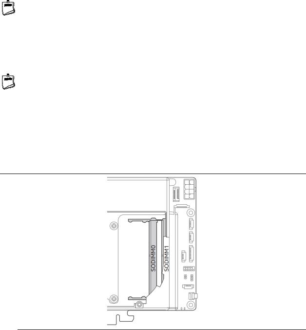
The SODIMM memory slots on the NUC 9 Extreme/Pro Kits is located underneath the NUC 9 Extreme/Pro Compute Element shroud door. See Figure 2.
Figure 2. SODIMM Location on NUC 9 Extreme/Pro Element
19
2.4.1Addressable Memory
The system has been validated with up to 64 GB of addressable system memory. Typically, the address space that is allocated for PCI Express configuration space, BIOS (SPI Flash device), and chipset overhead resides above the top of DRAM (total system memory). On a system that has 16 GB of system memory installed, it is not possible to use all of the installed memory due to system address space being allocated for other system critical functions. These functions include the following:
•BIOS/SPI Flash device (32 MB)
•Local APIC (19 MB)
•Direct Media Interface (40 MB)
•PCI Express configuration space (256 MB)
•PCH base address registers PCI Express ports (up to 256 MB)
•Memory-mapped I/O that is dynamically allocated for M.2 add-in cards (256 MB)
•Integrated graphics shared memory (up to 1.5 GB; 64 MB by default)
2.5Processor Graphics Subsystem
The NUC Extreme/Pro Kit supports graphics through either the Intel® UHD Graphics 630 or Intel® UHD Graphics P630.
For information about… |
Refer to: |
|
|
Intel Graphics Technologies |
http://www.intel.com/graphics |
|
|
2.5.1Integrated Graphics
The NUC Extreme/Pro Kit supports integrated graphics via the processor.
2.5.1.1High Definition Multimedia Interface* (HDMI*)
The HDMI port is HDMI 2.0a specification compliant and support standard, enhanced, or high definition video, plus multi-channel digital audio on a single cable. The port is compatible with all ATSC and DVB HDTV standards and supports thirty-two full range channels of lossless audio formats. The system can support a display at the maximum supported resolution of 4096 x 2160 @ 60 Hz, 24bpp.
For information about |
Refer to |
|
|
HDMI technology |
http://www.hdmi.org |
|
|
2.5.1.1.1Integrated Audio Provided by the HDMI Interfaces
The following audio technologies are supported by the HDMI 2.0a interface:
•192kHz/16-bit or 176.4 kHz/24-bit, 32 Channel
20
Product Description
2.5.1.1.2High-bandwidth Digital Content Protection (HDCP)
The HDMI Port supports HDCP 2.2. HDCP is the technology for protecting high definition content against unauthorized copy or interception between a source (computer, digital set top boxes, etc.) and the sink (panels, monitor, and TVs). The PCH supports HDCP 2.2 for content protection over wired displays.
2.5.1.2DisplayPort* via Type C
DisplayPort is a digital communication interface that utilizes differential signaling to achieve a high bandwidth bus interface designed to support connections between PCs and monitors, projectors, and TV displays. DisplayPort is suitable for display connections between consumer electronics devices such as high definition optical disc players, set top boxes, and TV displays. The Type C DisplayPort connectors are compliant with the DisplayPort 1.2 specification and thus have a maximum supported resolution of 4096 x 2160 @ 60Hz 24bpp.
DisplayPort output supports Multi-Stream Transport (MST) which allows for multiple independent video streams (daisy-chain connection with multiple monitors) over a single DisplayPort. This will require the use of displays that support DisplayPort 1.2 specification and allow for this feature.
For information about |
Refer to |
|
|
DisplayPort technology |
http://www.displayport.org |
|
|
2.6USB
The NUC 9 Extreme/Pro Kit supports eleven USB ports. All eleven ports are high-speed, fullspeed, and low-speed capable. The port arrangement is as follows:
•USB 3.1 Gen 2 ports:
Two ports are implemented with external front panel connectors (black)
Four ports are implemented with external back panel connectors (blue)
Two ports are implemented with as USB Type-C back panel connectors (black)
One port is implemented as an internal USB Type-A port in the front of the chassis.
•USB 2.0 ports:
Two ports via two single-port internal 1x4 1.25 mm pitch headers on NUC 9 Extreme/Pro Compute Element (black in white outline space)
NOTE |
Computer systems that have an unshielded cable attached to a USB port may not meet FCC Class B requirements, even if no device is attached to the cable. Use a shielded cable that meets the requirements for full-speed devices.
2.7Storage Options
The NUC 9 Extreme/Pro Kit provides the following Storage interfaces:
21
 Loading...