


 Loading...
Intel® Server Board S2600WT
Technical Product Specification (TPS)
Revision 1.0
August 2014
Intel® Server Boards and Systems

|
|
|
Intel® Server Board S2600WT TPS |
|
|
|
|
|
|
|
|
|
Revision History |
|
|
|
|
|
|
|
Date |
Revision |
Modifications |
|
|
|
Number |
|
|
|
August 2014 |
1..0 |
1st External Public Release |
|
ii |
Revision 1.0 |

Intel® Server Board S2600WT TPS
Disclaimers
Information in this document is provided in connection with Intel® products. No license, express or implied, by estoppel or otherwise, to any intellectual property rights is granted by this document. Except as provided in Intel's Terms and Conditions of Sale for such products, Intel assumes no liability whatsoever, and Intel disclaims any express or implied warranty, relating to sale and/or use of Intel products including liability or warranties relating to fitness for a particular purpose, merchantability, or infringement of any patent, copyright or other intellectual property right. Intel products are not intended for use in medical, lifesaving, or life sustaining applications. Intel may make changes to specifications and product descriptions at any time, without notice.
A "Mission Critical Application" is any application in which failure of the Intel Product could result, directly or indirectly, in personal injury or death. SHOULD YOU PURCHASE OR USE INTEL'S PRODUCTS FOR ANY SUCH MISSION CRITICAL APPLICATION, YOU SHALL INDEMNIFY AND HOLD INTEL AND ITS SUBSIDIARIES, SUBCONTRACTORS AND AFFILIATES, AND THE DIRECTORS, OFFICERS, AND EMPLOYEES OF EACH, HARMLESS AGAINST ALL CLAIMS COSTS, DAMAGES, AND EXPENSES AND REASONABLE ATTORNEYS' FEES ARISING OUT OF, DIRECTLY OR INDIRECTLY, ANY CLAIM OF PRODUCT LIABILITY, PERSONAL INJURY, OR DEATH ARISING IN ANY WAY OUT OF SUCH MISSION CRITICAL APPLICATION, WHETHER OR NOT INTEL OR ITS SUBCONTRACTOR WAS NEGLIGENT IN THE DESIGN, MANUFACTURE, OR WARNING OF THE INTEL PRODUCT OR ANY OF ITS PARTS.
Designers must not rely on the absence or characteristics of any features or instructions marked "reserved" or "undefined." Intel reserves these for future definition and shall have no responsibility whatsoever for conflicts or incompatibilities arising from future changes to them.
The Intel® Server Board S2600WT may contain design defects or errors known as errata which may cause the product to deviate from published specifications. Current characterized errata are available on request.
This document and the software described in it are furnished under license and may only be used or copied in accordance with the terms of the license. The information in this manual is furnished for informational use only, is subject to change without notice, and should not be construed as a commitment by Intel Corporation. Intel Corporation assumes no responsibility or liability for any errors or inaccuracies that may appear in this document or any software that may be provided in association with this document.
Except as permitted by such license, no part of this document may be reproduced, stored in a retrieval system, or transmitted in any form or by any means without the express written consent of Intel Corporation.
Copies of documents which have an order number and are referenced in this document, or other Intel® Literature, may be obtained by calling 1-800-548-4725, or go to: http://www.intel.com/design/Literature.htm.
Intel and Xeon are trademarks or registered trademarks of Intel Corporation.
*Other brands and names may be claimed as the property of others.
Copyright © 2014 Intel Corporation. All rights reserved.
.
Revision 1.0 |
iii |

Intel® Server Board S2600WT TPS
Table of Contents
1. |
Introduction........................................................................................................................................ |
1 |
|
|
1.1 |
Chapter Outline.................................................................................................................................... |
1 |
|
1.2 |
Server Board Use Disclaimer.......................................................................................................... |
1 |
2. |
Product Features Overview............................................................................................................. |
2 |
|
|
2.1 |
Server Board Component/Feature Identification.................................................................. |
4 |
|
2.2 |
Product Architecture Overview..................................................................................................... |
8 |
|
2.3 |
System Software Overview ............................................................................................................. |
9 |
|
2.3.1 |
System BIOS.......................................................................................................................................... |
9 |
|
2.3.2 |
Field Replaceable Unit (FRU) and Sensor Data Record (SDR) Data............................. |
13 |
2.3.3Baseboard Management Controller (BMC) & Management Engine (ME) Firmware13
3. |
Processor Support.......................................................................................................................... |
14 |
|
|
3.1 |
Processor Socket Assembly ........................................................................................................ |
14 |
|
3.2 |
Processor Thermal Design Power (TDP) Support .............................................................. |
15 |
|
3.3 |
Processor Population Rules......................................................................................................... |
15 |
|
3.4 |
Processor Initialization Error Summary.................................................................................. |
16 |
|
3.5 |
Processor Function Overview ..................................................................................................... |
18 |
|
3.5.1 |
Processor Core Features:.............................................................................................................. |
18 |
|
3.5.2 |
Supported Technologies: ............................................................................................................. |
18 |
4. |
System Memory .............................................................................................................................. |
21 |
|
|
4.1 |
Memory Sub-system Architecture............................................................................................ |
21 |
|
4.2 |
IMC Modes of operation................................................................................................................ |
22 |
|
4.3 |
Memory RASM Features................................................................................................................ |
22 |
|
4.4 |
Supported Memory ......................................................................................................................... |
23 |
|
4.5 |
NVDIMM Support ............................................................................................................................. |
24 |
|
4.6 |
Memory Slot Identification and Population Rules ............................................................. |
24 |
|
4.6.1 |
Memory Interleaving Support..................................................................................................... |
27 |
|
4.6.2 |
NUMA Configuration Support..................................................................................................... |
27 |
|
4.7 |
System Memory Sizing and Publishing................................................................................... |
27 |
|
4.7.1 |
Effects of Memory Configuration on Memory Sizing ........................................................ |
27 |
|
4.7.2 |
Publishing System Memory ......................................................................................................... |
28 |
|
4.8 |
Memory Initialization...................................................................................................................... |
29 |
|
4.8.1 |
DIMM Discovery............................................................................................................................... |
29 |
|
4.8.2 |
DIMM Population Validation Check.......................................................................................... |
29 |
|
4.8.3 |
Channel Training .............................................................................................................................. |
30 |
5. |
System I/O ....................................................................................................................................... |
32 |
|
|
5.1 |
PCIe* Support .................................................................................................................................... |
32 |
iv |
Revision 1.0 |
|
|
Intel® Server Board S2600WT TPS |
|
|
5.2 |
PCIe* Enumeration and Allocation ........................................................................................... |
33 |
|
5.3 |
PCIe* Non-Transparent Bridge (NTB) ...................................................................................... |
33 |
|
5.4 |
Add-in Card Support ...................................................................................................................... |
34 |
|
5.4.1 |
Riser Card Support .......................................................................................................................... |
35 |
|
5.4.2 |
I/O Module Support ........................................................................................................................ |
38 |
|
5.4.3 |
Intel® Integrated RAID Option...................................................................................................... |
39 |
|
5.5 |
Serial ATA (SATA) Support........................................................................................................... |
40 |
|
5.5.1 |
Staggered Disk Spin-Up ................................................................................................................ |
42 |
|
5.6 |
Embedded SATA SW-RAID support......................................................................................... |
42 |
|
5.6.1 |
Intel® Rapid Storage Technology (RSTe) 4.0 ......................................................................... |
42 |
|
5.6.2 |
Intel® Embedded Server RAID Technology 2 (ESRT2)....................................................... |
43 |
|
5.7 |
Network Interface............................................................................................................................. |
44 |
|
5.7.1 |
Intel® Ethernet Controller Options............................................................................................ |
45 |
|
5.7.2 |
Factory Programmed MAC Address Assignments ............................................................. |
45 |
|
5.8 |
Video Support ................................................................................................................................... |
45 |
|
5.8.1 |
Dual Video and Add-In Video Adapters ................................................................................. |
46 |
|
5.8.2 |
Setting Video Configuration Options using the BIOS Setup Utility ............................ |
48 |
|
5.9 |
USB Support....................................................................................................................................... |
50 |
|
5.9.1 |
Low Profile eUSB SSD Support.................................................................................................. |
50 |
|
5.10 |
Serial Ports.......................................................................................................................................... |
51 |
6. |
System Security .............................................................................................................................. |
53 |
|
|
6.1 |
BIOS Setup Utility Security Options Menu............................................................................ |
53 |
|
6.1.1 |
Password Setup ................................................................................................................................ |
53 |
|
6.1.2 |
System Administrator Password Rights ................................................................................. |
54 |
|
6.1.3 |
Authorized System User Password Rights and Restrictions.......................................... |
54 |
|
6.1.4 |
Front Panel Lockout........................................................................................................................ |
54 |
|
6.2 |
Trusted Platform Module (TPM) Support .............................................................................. |
55 |
|
6.2.1 |
TPM security BIOS ........................................................................................................................... |
55 |
|
6.2.2 |
Physical Presence ............................................................................................................................ |
56 |
|
6.2.3 |
TPM Security Setup Options ....................................................................................................... |
56 |
|
6.3 |
Intel® Trusted Execution Technology....................................................................................... |
57 |
7. |
Platform Management................................................................................................................... |
58 |
|
|
7.1 |
Management Feature Set Overview ......................................................................................... |
58 |
|
7.1.1 |
IPMI 2.0 Features Overview ......................................................................................................... |
58 |
|
7.1.2 |
Non IPMI Features Overview ....................................................................................................... |
59 |
|
7.2 |
Platform Management Features and Functions.................................................................. |
61 |
|
7.2.1 |
Power Sub-system........................................................................................................................... |
61 |
|
7.2.2 |
Advanced Configuration and Power Interface (ACPI) ....................................................... |
61 |
Revision 1.0 |
v |

|
Intel® Server Board S2600WT TPS |
|
7.2.3 |
System Initialization........................................................................................................................ |
61 |
7.2.4 |
Watchdog Timer............................................................................................................................... |
62 |
7.2.5 |
System Event Log (SEL)................................................................................................................. |
62 |
7.3 |
Sensor Monitoring ........................................................................................................................... |
62 |
7.3.1 |
Sensor Scanning............................................................................................................................... |
63 |
7.3.2 |
Sensor Rearm Behavior ................................................................................................................. |
63 |
7.3.3 |
BIOS Event-Only Sensors ............................................................................................................. |
64 |
7.3.4 |
Margin Sensors.................................................................................................................................. |
64 |
7.3.5 |
IPMI Watchdog Sensor .................................................................................................................. |
64 |
7.3.6 |
BMC Watchdog Sensor.................................................................................................................. |
64 |
7.3.7 |
BMC System Management Health Monitoring..................................................................... |
64 |
7.3.8 |
VR Watchdog Timer........................................................................................................................ |
64 |
7.3.9 |
System Airflow Monitoring........................................................................................................... |
64 |
7.3.10 |
Thermal Monitoring ........................................................................................................................ |
65 |
7.3.11 |
Processor Sensors ........................................................................................................................... |
68 |
7.3.12 |
Voltage Monitoring.......................................................................................................................... |
70 |
7.3.13 |
Fan Monitoring .................................................................................................................................. |
70 |
7.3.14 |
Standard Fan Management.......................................................................................................... |
72 |
7.3.15 |
Power Management Bus (PMBus*)............................................................................................ |
78 |
7.3.16 |
Power Supply Dynamic Redundancy Sensor ....................................................................... |
78 |
7.3.17 |
Component Fault LED Control ................................................................................................... |
79 |
7.3.18 |
NMI (Diagnostic Interrupt) Sensor............................................................................................. |
80 |
7.3.19 |
LAN Leash Event Monitoring....................................................................................................... |
80 |
7.3.20 |
Add-in Module Presence Sensor............................................................................................... |
80 |
7.3.21 |
CMOS Battery Monitoring............................................................................................................. |
80 |
8. Intel® Intelligent Power Node Manager (NM) Support Overview ........................................ |
81 |
|
8.1 |
Hardware Requirements ............................................................................................................... |
81 |
8.2 |
Features................................................................................................................................................ |
81 |
8.3 |
ME System Management Bus (SMBus*) interface............................................................... |
81 |
8.4 |
PECI 3.0 ................................................................................................................................................ |
82 |
8.5 |
NM “Discovery” OEM SDR............................................................................................................. |
82 |
8.6 |
SmaRT/CLST ...................................................................................................................................... |
82 |
8.6.1 |
Dependencies on PMBus*-compliant Power Supply Support...................................... |
83 |
9. Basic and Advanced Server Management Features............................................................... |
84 |
|
9.1 |
Dedicated Management Port ...................................................................................................... |
85 |
9.2 |
Embedded Web Server.................................................................................................................. |
85 |
9.3 |
Advanced Management Feature Support (RMM4 Lite)................................................... |
87 |
9.3.1 |
Keyboard, Video, Mouse (KVM) Redirection ......................................................................... |
87 |
vi |
Revision 1.0 |
|
Intel® Server Board S2600WT TPS |
|
9.3.2 |
Remote Console ............................................................................................................................... |
88 |
9.3.3 |
Performance....................................................................................................................................... |
88 |
9.3.4 |
Security................................................................................................................................................. |
89 |
9.3.5 |
Availability........................................................................................................................................... |
89 |
9.3.6 |
Usage..................................................................................................................................................... |
89 |
9.3.7 |
Force-enter BIOS Setup ................................................................................................................ |
89 |
9.3.8 |
Media Redirection............................................................................................................................ |
89 |
10. On-board Connector/Header Overview.................................................................................... |
91 |
|
10.1 |
Power Connectors ........................................................................................................................... |
91 |
10.1.1 |
Main Power ......................................................................................................................................... |
91 |
10.1.2 |
Hot Swap Backplane Power Connector.................................................................................. |
92 |
10.1.3 |
Peripheral Drive Power Connector ........................................................................................... |
93 |
10.1.4 |
Riser Card Supplemental 12V Power Connectors.............................................................. |
93 |
10.2 |
Front Panel Headers and Connectors ..................................................................................... |
94 |
10.2.1 |
Front Panel Button and LED Support...................................................................................... |
94 |
10.2.2 |
Front Panel LED and Control Button Features Overview................................................ |
95 |
10.2.3 |
Front Panel USB 2.0 Connector ................................................................................................. |
96 |
10.2.4 |
Front Panel USB 3.0 Connector ................................................................................................. |
97 |
10.2.5 |
Front Panel Video Connector...................................................................................................... |
97 |
10.2.6 |
Intel® Local Control Panel Connector....................................................................................... |
97 |
10.3 |
On-Board Storage Option Connectors ................................................................................... |
98 |
10.3.1 |
Single Port SATA Only Connectors .......................................................................................... |
98 |
10.3.2 |
Internal Type-A USB Connector ................................................................................................ |
99 |
10.3.3 |
Internal 2mm Low Profile eUSB SSD Connector ................................................................ |
99 |
10.4 |
System Fan Connectors.............................................................................................................. |
100 |
10.5 |
Other Connectors and Headers .............................................................................................. |
101 |
10.5.1 |
Chassis Intrusion Header ........................................................................................................... |
101 |
10.5.2 |
Storage Device Activity LED Header...................................................................................... |
101 |
10.5.3 |
Intelligent Platform Management Bus (IPMB) Connector ............................................ |
101 |
10.5.4 |
Hot Swap Backplane I2C* Connectors ................................................................................. |
102 |
10.5.5 |
SMBus Connector.......................................................................................................................... |
102 |
11. Reset and Recovery Jumpers..................................................................................................... |
103 |
|
11.1 |
BIOS Default Jumper Block ...................................................................................................... |
103 |
11.2 |
Serial Port ‘A’ Configuration Jumper .................................................................................... |
104 |
11.3 |
Password Clear Jumper Block................................................................................................. |
104 |
11.4 |
Management Engine (ME) Firmware Force Update Jumper Block........................... |
104 |
11.5 |
BMC Force Update Jumper Block .......................................................................................... |
105 |
11.6 |
BIOS Recovery Jumper............................................................................................................... |
106 |
Revision 1.0 |
vii |

|
Intel® Server Board S2600WT TPS |
|
12. Light Guided Diagnostics............................................................................................................ |
107 |
|
12.1 |
System ID LED ................................................................................................................................ |
108 |
12.2 |
System Status LED........................................................................................................................ |
108 |
12.3 |
BMC Boot/Reset Status LED Indicators ............................................................................... |
111 |
12.4 |
Post Code Diagnostic LEDs....................................................................................................... |
111 |
12.5 |
Fan Fault LEDs................................................................................................................................ |
111 |
12.6 |
Memory Fault LEDs ...................................................................................................................... |
111 |
12.7 |
CPU Fault LEDs............................................................................................................................... |
111 |
13. Power Supply Specification Guidelines .................................................................................. |
112 |
|
13.1 |
Power Supply DC Output Connector.................................................................................... |
112 |
13.2 |
Power Supply DC Output Specification............................................................................... |
113 |
13.2.1 |
Output Power/Currents.............................................................................................................. |
113 |
13.2.2 |
Standby Output ............................................................................................................................. |
113 |
13.2.3 |
Voltage Regulation ....................................................................................................................... |
113 |
13.2.4 |
Dynamic Loading........................................................................................................................... |
113 |
13.2.5 |
Capacitive Loading ....................................................................................................................... |
114 |
13.2.6 |
Grounding......................................................................................................................................... |
114 |
13.2.7 |
Closed loop stability .................................................................................................................... |
114 |
13.2.8 |
Residual Voltage Immunity in Standby mode................................................................... |
114 |
13.2.9 |
Common Mode Noise.................................................................................................................. |
114 |
13.2.10 |
Soft Starting .................................................................................................................................... |
114 |
13.2.11 |
Zero Load Stability Requirements ......................................................................................... |
114 |
13.2.12 |
Hot Swap Requirements............................................................................................................. |
114 |
13.2.13 |
Forced Load Sharing.................................................................................................................... |
114 |
13.2.14 |
Ripple/Noise.................................................................................................................................... |
115 |
13.2.15 |
Timing Requirements .................................................................................................................. |
115 |
Appendix A: Integration and Usage Tips........................................................................................ |
117 |
|
Appendix B: Integrated BMC Sensor Tables.................................................................................. |
118 |
|
Appendix C: Management Engine Generated SEL Event Messages ......................................... |
132 |
|
Appendix D: POST Code Diagnostic LED Decoder ....................................................................... |
134 |
|
Appendix E: POST Code Errors......................................................................................................... |
141 |
|
Appendix F: Supported Intel® Server Systems .............................................................................. |
147 |
|
viii |
Revision 1.0 |

Intel® Server Board S2600WT TPS |
|
List of Figures |
|
Figure 1. Server Board Component/Features Identification........................................................................ |
4 |
Figure 2. Intel® Server Board S2600WT External I/O Connector Layout ................................................ |
5 |
Figure 3. Intel® Light Guided Diagnostics - DIMM Fault LEDs...................................................................... |
5 |
Figure 4. Intel® Light Guided Diagnostic LED Identification.......................................................................... |
6 |
Figure 5. Jumper Block Identification.................................................................................................................... |
7 |
Figure 6. Intel® Server Board S2600WT Architectural Block Diagram ..................................................... |
8 |
Figure 7. Processor Socket Assembly ............................................................................................................... |
14 |
Figure 8. LGA2011-3 ILM (Narrow) ...................................................................................................................... |
14 |
Figure 9. Memory Sub-system Block Diagram................................................................................................ |
21 |
Figure 10. Memory Slots Definition..................................................................................................................... |
24 |
Figure 11. Intel® Server Board S2600WT Memory Slot Layout................................................................ |
25 |
Figure 12. On-board Add-in Card Support ...................................................................................................... |
34 |
Figure 13. 1U one slot PCIe* riser card (iPN – F1UL16RISER2)................................................................ |
36 |
Figure 14. 2U three PCIe* slot riser card (iPN – A2UL8RISER2)............................................................... |
36 |
Figure 15. 2U two PCIe* slot riser card (iPN – A2UL16RISER2) ............................................................... |
37 |
Figure 16. 2U three PCIx/PCIe* slot riser (iPN - A2ULPCIXRISER2) ....................................................... |
37 |
Figure 17. 2U two PCIe* slot (Low Profile) PCIe* Riser card (iPN – A2UX8X4RISER) – Riser Slot |
|
#3 compatible only ............................................................................................................................................ |
38 |
Figure 18. Server Board Layout - I/O Module Connector........................................................................... |
38 |
Figure 19. Server Board Layout – Intel® Integrated RAID Module Option Placement.................... |
39 |
Figure 20. Onboard SATA Features..................................................................................................................... |
40 |
Figure 21. SATA RAID 5 Upgrade Key................................................................................................................. |
44 |
Figure 22. Network Interface Connectors......................................................................................................... |
44 |
Figure 23. External RJ45 NIC Port LED Definition......................................................................................... |
45 |
Figure 24. BIOS Setup Utility - Video Configuration Options................................................................... |
48 |
Figure 25. Onboard USB Port Support .............................................................................................................. |
50 |
Figure 26. Low Profile eUSB SSD Support ....................................................................................................... |
50 |
Figure 27. High-level Fan Speed Control Process......................................................................................... |
75 |
Figure 28. Intel® RMM4 Lite Activation Key Installation.............................................................................. |
85 |
Figure 29. High Power Add-in Card 12V Auxiliary Power Cable Option.............................................. |
93 |
Figure 30. System Fan Connector Pin-outs .................................................................................................. |
100 |
Figure 31. System Fan Connector Placement.............................................................................................. |
100 |
Figure 32. Reset and Recovery Jumper Block Location........................................................................... |
103 |
Figure 33. On-Board Diagnostic LED Placement ........................................................................................ |
107 |
Figure 34. DIMM Fault LED Placement............................................................................................................ |
108 |
Figure 35. Turn On/Off Timing (Power Supply Signals)........................................................................... |
116 |
Revision 1.0 |
ix |

Intel® Server Board S2600WT TPS |
|
Figure 36. POST Diagnostic LED Location..................................................................................................... |
134 |
Figure 37. Intel® Server System R1000WT.................................................................................................... |
147 |
Figure 38. Intel® Server System R2000WT.................................................................................................... |
150 |
x |
Revision 1.0 |
Intel® Server Board S2600WT TPS |
|
List of Tables |
|
Table 1. Intel® Server Board S2600WT Feature Set......................................................................................... |
2 |
Table 2. POST Hot-Keys........................................................................................................................................... |
11 |
Table 3. Mixed Processor Configurations Error Summary......................................................................... |
16 |
Table 4. DDR4 RDIMM & LRDIMM Support ..................................................................................................... |
23 |
Table 5. Intel® Server Board S2600WT Memory Slot Identification ...................................................... |
25 |
Table 6. DIMM Population Matrix......................................................................................................................... |
26 |
Table 7. PCIe* Port Routing CPU #1.................................................................................................................... |
32 |
Table 8. PCIe* Port Routing – CPU #2 ............................................................................................................... |
33 |
Table 9. Riser Card #1 - PCIe* Root Port Mapping........................................................................................ |
35 |
Table 10. Riser Card #2 - PCIe* Root Port Mapping ..................................................................................... |
35 |
Table 11. Riser Slot #3 - PCIe* Root Port Mapping....................................................................................... |
36 |
Table 12. Supported Intel® I/O Module Options ............................................................................................ |
39 |
Table 13. SATA and sSATA Controller BIOS Utility Setup Options ....................................................... |
41 |
Table 14. SATA and sSATA Controller Feature Support............................................................................ |
41 |
Table 15. Video Modes ............................................................................................................................................. |
46 |
Table 16. Serial A Connector Pin-out................................................................................................................. |
51 |
Table 17. Serial-B Connector Pin-out ................................................................................................................ |
52 |
Table 18. TPM Setup Utility – Security Configuration Screen Fields .................................................... |
57 |
Table 19. Server Board Power Control Sources............................................................................................. |
61 |
Table 20. ACPI Power States.................................................................................................................................. |
61 |
Table 21. Processor Sensors.................................................................................................................................. |
68 |
Table 22. Processor Status Sensor Implementation.................................................................................... |
68 |
Table 23. Component Fault LEDs......................................................................................................................... |
79 |
Table 24. Intel® Remote Management Module 4 (RMM4) Options......................................................... |
84 |
Table 25. Basic and Advanced Server Management Features Overview............................................. |
84 |
Table 26. Main Power (Slot 1) Connector Pin-out (“MAIN PWR 1”)...................................................... |
91 |
Table 27. Main Power (Slot 2) Connector Pin-out ("MAIN PWR 2”) ....................................................... |
92 |
Table 28. Hot Swap Backplane Power Connector Pin-out (“HSBP PWR") .......................................... |
92 |
Table 29. Peripheral Drive Power Connector Pin-out ("Peripheral_PWR")......................................... |
93 |
Table 30. Riser Slot Auxiliary Power Connector Pin-out ("OPT_12V_PWR”)..................................... |
93 |
Table 31. Front Panel Features ............................................................................................................................. |
94 |
Table 32. Front Panel Connector Pin-out ("Front Panel” and “Storage FP”)...................................... |
94 |
Table 33. Power/Sleep LED Functional States ............................................................................................... |
95 |
Table 34. NMI Signal Generation and Event Logging .................................................................................. |
96 |
Table 35. Front Panel USB 2.0 Connector Pin-out ("FP_USB_2.0_5-6 ")............................................. |
96 |
Table 36. Front Panel USB 2.0/3.0 Connector Pin-out (“FP_USB_2.0/ 3.0”) ..................................... |
97 |
Revision 1.0 |
xi |

Intel® Server Board S2600WT TPS |
|
Table 37. Front Panel Video Connector Pin-out ("FP VIDEO")................................................................. |
97 |
Table 38. Intel Local Control Panel Connector Pin-out ("LCP")............................................................... |
98 |
Table 39. Single Port SATA Connector Pin-out ("SATA 4" & "SATA 5") ............................................... |
98 |
Table 40. SATA SGPIO Connector Pin-out ("SATA_SGPIO")..................................................................... |
99 |
Table 41. Internal Type-A USB Connector Pin-out ("USB 2.0") ............................................................... |
99 |
Table 42. Internal eUSB Connector Pin-out ("eUSB SSD") ........................................................................ |
99 |
Table 43. Chassis Intrusion Header Pin-out ("CHAS_INTR") .................................................................. |
101 |
Table 44. Hard Drive Activity Header Pin-out ("HDD_LED")................................................................... |
101 |
Table 45. IPMB Connector Pin-out................................................................................................................... |
101 |
Table 46. Hot-Swap Backplane I2C* Connector Pin-out......................................................................... |
102 |
Table 47. SMBus Connector Pin-out................................................................................................................ |
102 |
Table 48. System Status LED State Definitions........................................................................................... |
109 |
Table 49. BMC Boot/Reset Status LED Indicators ...................................................................................... |
111 |
Table 50. Power Supply DC Power Output Connector Pinout.............................................................. |
112 |
Table 51. Minimum Load Ratings...................................................................................................................... |
113 |
Table 52. Voltage Regulation Limits ................................................................................................................ |
113 |
Table 53. Transient Load Requirements ........................................................................................................ |
113 |
Table 54. Capacitive Loading Conditions....................................................................................................... |
114 |
Table 55. Ripples and Noise................................................................................................................................ |
115 |
Table 56. Timing Requirements......................................................................................................................... |
115 |
Table 57. BMC Core Sensors............................................................................................................................... |
120 |
Table 58. Server Platform Services Firmware Health Event .................................................................. |
132 |
Table 59. Node Manager Health Event ........................................................................................................... |
133 |
Table 60. POST Progress Code LED Example.............................................................................................. |
135 |
Table 61. MRC Progress Codes .......................................................................................................................... |
135 |
Table 62. MRC Fatal Error Codes....................................................................................................................... |
136 |
Table 63. POST Progress Codes........................................................................................................................ |
138 |
Table 64. POST Error Codes and Messages.................................................................................................. |
141 |
Table 65. POST Error Beep Codes.................................................................................................................... |
146 |
Table 66. Integrated BMC Beep Codes ........................................................................................................... |
146 |
Table 67. Intel® Server System R1000WT Product Family Feature Set............................................. |
147 |
Table 68. Intel® Server System R2000WT Product Family Feature Set............................................. |
150 |
xii |
Revision 1.0 |
Intel® Server Board S2600WT TPS
<This page is intentionally left blank.>
Revision 1.0 |
xiii |

Intel® Server Board S2600WT TPS
1.Introduction
This Technical Product Specification (TPS) provides board-specific information detailing the features, functionality, and high-level architecture of the Intel® Server Board S2600WT.
Design-level information related to specific server board components and subsystems can be obtained by ordering External Product Specifications (EPS) or External Design Specifications (EDS) related to this server generation. EPS and EDS documents are made available under NDA with Intel and must be ordered through your local Intel representative. See the Reference Documents section for a list of available documents.
1.1Chapter Outline
This document is divided into the following chapters:
Chapter 1 – Introduction
Chapter 2 – Product Features Overview
Chapter 3 – Processor Support
Chapter 4 – System Memory
Chapter 5 – System I/O
Chapter 6 – System Security
Chapter 7 – Platform Management
Chapter 8 – Intel® Intelligent Power Node Manager (NM) Support Overview
Chapter 9 – Basic and Advanced Server Management Features
Chapter 10 – On-Board Connector and Header Overview
Chapter 11 – Reset and Recovery Jumpers
Chapter 12 – Light-Guided Diagnostics
Chapter 13 – Power Supply Specification Guidelines
Appendix A – Integration and Usage Tips
Appendix B – Integrated BMC Sensor Tables
Appendix C – Management Engine Generated SEL Event Messages
Appendix D – POST Code Diagnostic LED Decoder
Appendix E – POST Code Errors
Appendix F – Supported Intel® Server Systems
1.2Server Board Use Disclaimer
Intel Corporation server boards support add-in peripherals and contain a number of high-density VLSI and power delivery components that need adequate airflow to cool. Intel ensures through its own chassis development and testing that when Intel server building blocks are used together, the fully integrated system will meet the intended thermal requirements of these components. It is the responsibility of the system integrator who chooses not to use Intel developed server building blocks to consult vendor datasheets and operating parameters to determine the amount of airflow required for their specific application and environmental conditions. Intel Corporation cannot be held responsible if components fail or the server board does not operate correctly when used outside any of its published operating or non-operating limits.
1 |
Revision 1.0 |

Intel® Server Board S2600WT TPS
2.Product Features Overview
The Intel® Server Board S2600WT is a monolithic printed circuit board assembly with features that are intended for high density 1U and 2U rack mount servers. This server board is designed to support the Intel® Xeon® processor E5-2600 v3 product family. Previous generation Intel® Xeon® processors are not supported.
The server board is offered with either of the two following on-board networking options:
•Intel® Ethernet Controller X540, supporting 10 GbE (Intel Server Board Product Code - S2600WTT)
•Intel® Ethernet Controller I350, supporting 1 GbE (Intel Server Board Product Code – S2600WT2)
All other onboard features will be identical.
|
Table 1. Intel® Server Board S2600WT Feature Set |
|
|
|
|
Feature |
Description |
|
|
• Two LGA2011-3 (Socket R3) processor sockets |
|
Processor Support |
• Support for one or two Intel® Xeon® processors E5-2600 v3 product family |
|
|
• Maximum supported Thermal Design Power (TDP) of up to 145 W |
|
|
|
|
|
• 24 DIMM slots – 3 DIMMs/Channel – 4 memory channels per processor |
|
|
• Registered DDR4 (RDIMM), Load Reduced DDR4 (LRDIMM) |
|
Memory |
• Memory data transfer rates: |
|
o DDR4 RDIMM: 1600 MT/s (3DPC), 1866 MT/s (2DPC) and 2133 MT/s (1DPC) |
||
|
||
|
o DDR4 LRDIMM: 1600 MT/s (3DPC), 2133 MT/s (2DPC & 1DPC) |
|
|
• DDR4 standard I/O voltage of 1.2V |
|
|
|
|
Chipset |
Intel® C612 chipset |
|
|
• DB-15 Video connector |
|
|
• RJ-45 Serial Port A connector |
|
|
• Dual RJ-45 Network Interface connectors supporting either : |
|
External (Back Panel) |
o 10 GbE RJ-45 connectors (Intel Server Board Product Code – S2600WTT) |
|
I/O connections |
or |
|
|
o 1 GbE RJ-45 connectors (Intel Server Board Product Code – S2600WT2) |
|
|
• Dedicated RJ-45 server management port |
|
|
• Three USB 2.0 / 3.0 connectors |
|
|
|
|
|
• One Type-A USB 2.0 connector |
|
|
• One 2x5 pin connector providing front panel support for two USB 2.0 ports |
|
|
• One 2x10 pin connector providing front panel support for two USB 2.0 / 3.0 ports |
|
Internal I/O |
• One 2x15 pin SSI-EEB compliant Standard Front Panel header |
|
connectors/headers |
• One 2x15 high density Storage Front Panel connector |
|
|
• One 2x7pin Front Panel Video connector |
|
|
• One 1x7pin header for optional Intel® Local Control Panel support |
|
|
• One DH-10 Serial Port B connector |
|
|
|
|
PCIe* Support |
• PCIe* 3.0 (2.5, 5, 8 GT/s) – backwards compatible with PCIe* Gen 1 and Gen 2 devices |
|
1U Server – Riser Card |
• Server board includes two PCIe* 3.0 compatible riser card only slots |
|
Support |
o Riser #1 – PCIe* 3.0 x24 – 1 PCIe* Full Height / Half Length add-in card support in 1U |
|
|
o Riser #2 – PCIe* 3.0 x24 – 1 PCIe* Full Height / Half Length add-in card support in 1U |
Revision 1.0 |
2 |

|
|
Intel® Server Board S2600WT TPS |
|
|
|
|
|
Feature |
|
Description |
|
|
• Server board includes three PCIe* 3.0 compatible riser card only slots: |
||
|
|
o Riser #1 – PCIe* 3.0 x24 – up to 3 PCIe* slots in 2U |
|
2U Server – Riser Card |
|
o Riser #2 – PCIe* 3.0 x24 – up to 3 PCIe* slots in 2U |
|
Support |
|
o Riser #3 – PCIe* 3.0 x8 + DMI x4 (PCIe* 2.0 compatible) – up to 2 PCIe* slots in 2U |
|
|
• With three riser cards installed, up to 8 possible add-in cards can be supported: |
||
|
|
o 4 Full Height / Full Length + 2 Full Height / Half Length add-in cards via Risers #1 and #2 |
|
|
|
o 2 low profile add-in cards via Riser #3 |
|
|
The server board includes a proprietary on-board connector allowing for the installation of a variety of |
||
|
available I/O modules. An installed I/O module can be supported in addition to standard on-board |
||
|
features and add-in PCIe* cards. |
||
|
• |
AXX4P1GBPWLIOM – Quad port RJ45 1 GbE based on Intel® Ethernet Controller I350 |
|
Available I/O Module |
• |
AXX10GBTWLIOM – Dual port RJ-45 10GBase-T I/O Module based on Intel® Ethernet Controller |
|
|
x540 |
||
Options |
• |
AXX10GBNIAIOM – Dual port SFP+ 10 GbE module based on Intel® 82599 10 GbE controller |
|
|
|||
|
• |
AXX1FDRIBIOM – Single port QSFP FDR 56 GT/S speed InfiniBand* module |
|
|
• |
AXX2FDRIBIOM – Dual port QSFP FDR 56 GT/S speed infiniband* module |
|
|
• |
AXX1P40FRTIOM – Single port QSFP+ 40 GbE module |
|
|
• |
AXX2P40FRTIOM – Dual port QSFP+ 40 GbE module |
|
|
|
||
|
• Six system fans supported in two different connector formats: hot swap (2U) and cabled (1U) |
||
System Fan Support |
o |
Six 10-pin managed system fan headers (Sys_Fan 1-6) – Used for 1U system configuration |
|
|
o |
Six 6-pin hot swap capable managed system fan connectors (Sys_Fan 1-6) – Used for 2U system |
|
|
|
configuration |
|
|
|
||
Video |
• Integrated 2D Video Controller |
||
• 16 MB DDR3 Memory |
|||
|
|||
|
|
||
|
• 10x SATA 6Gbps ports (6Gb/s, 3 Gb/s and 1.5Gb/s transfer rates are supported) |
||
|
o |
Two 7-pin single port SATA connectors capable of supporting up to 6 Gb/sec |
|
On-board storage |
o |
Two 4-port mini-SAS HD (SFF-8643) connectors capable of supporting up to 6 Gb/sec SATA |
|
• One eUSB 2x5 pin connector to support 2mm low-profile eUSB solid state devices |
|||
controllers and |
|||
• Optional SAS IOC/ROC support via on-board Intel® Integrated RAID module connector |
|||
options |
|||
• Embedded Software SATA RAID |
|||
|
|||
|
|
o Intel® Rapid Storage RAID Technology (RSTe) 4.0 |
|
|
|
o Intel® Embedded Server RAID Technology 2 (ESRT2) with optional RAID 5 key support |
|
Security |
• Intel® Trusted Platform Module (TPM) - AXXTPME5 (Accessory Option) |
||
|
• Integrated Baseboard Management Controller, IPMI 2.0 compliant |
||
Server Management |
• Support for Intel® Server Management Software |
||
• On-board RJ45 management interface |
|||
|
• Intel® Remote Management Module 4 Lite support (Accessory Option) |
||
3 |
Revision 1.0 |

Intel® Server Board S2600WT TPS
2.1Server Board Component/Feature Identification
The following illustration provides a general overview of the server board, identifying key feature and component locations.
Figure 1. Server Board Component/Features Identification
Revision 1.0 |
4 |

Intel® Server Board S2600WT TPS
The back edge of the server board includes several external connectors to support the following features:
A – RJ45 Networking Port – NIC #1
B – RJ45 Networking Port – NIC #2
C – Video
D – RJ45 Serial ‘A’ Port
E – Stacked 3-port USB 2.0 / 3.0
F – RJ45 Dedicated Management Port
Figure 2. Intel® Server Board S2600WT External I/O Connector Layout
Figure 3. Intel® Light Guided Diagnostics - DIMM Fault LEDs
5 |
Revision 1.0 |
Intel® Server Board S2600WT TPS
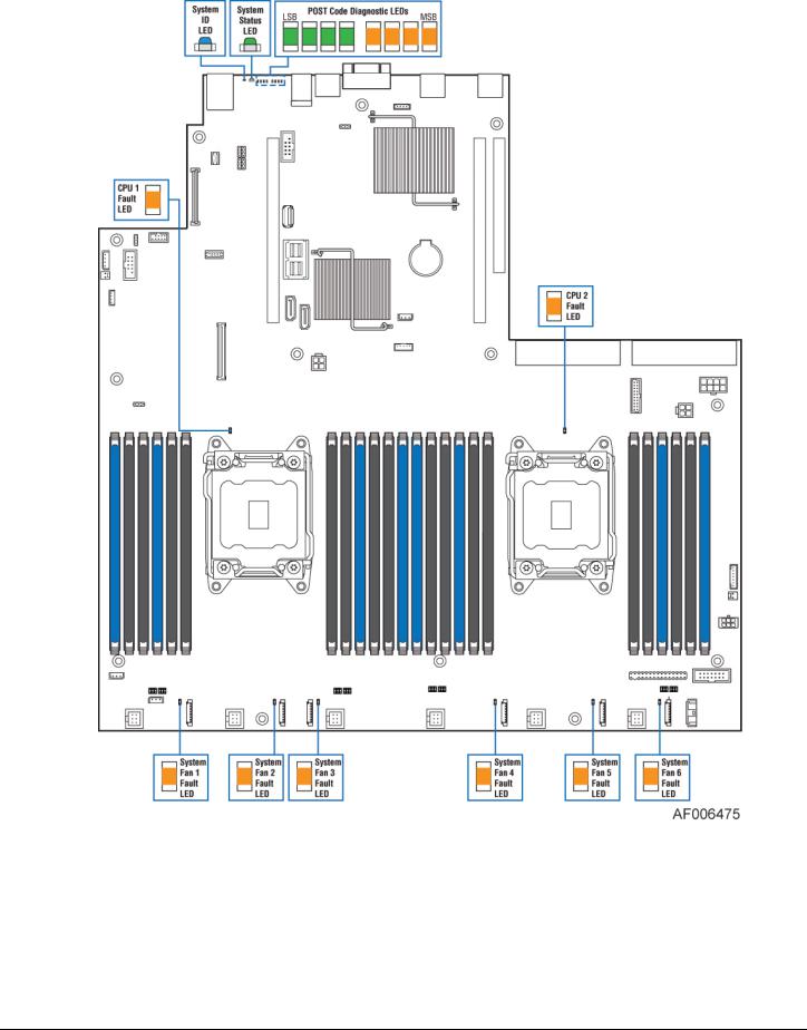
Figure 4. Intel® Light Guided Diagnostic LED Identification
Note: See Appendix D for POST Code Diagnostic LED decoder information
Revision 1.0 |
6 |
Intel® Server Board S2600WT TPS
Figure 5. Jumper Block Identification
See Chapter 11 - Reset & Recovery Jumpers for additional details.
7 |
Revision 1.0 |

Intel® Server Board S2600WT TPS
2.2Product Architecture Overview
The architecture of Intel® Server Board S2600WT is developed around the integrated features and functions of the Intel® Xeon® processor E5-2600 v3 product family, the Intel® C612 chipset, Intel® Ethernet Controllers I350 1 GbE or X540 10 GbE, and the Emulex* Pilot-III Baseboard Management Controller.
The following diagram provides an overview of the server board architecture, showing the features and interconnects of each of the major sub-system components.
|
CPU-1 |
|
CPU-2 |
|
DDR4 – CH0 |
|
|
|
|
|
|
|
|
|
|
|
|
|
CH0 – DDR4 |
DDR4 – CH1 |
Intel® Xeon® |
QPI 9.6 GT/s |
Intel® Xeon® |
CH1 – DDR4 |
|
|
|||
DDR4 – CH2 |
E5-2600 v3 |
|
E5-2600 v3 |
CH2 – DDR4 |
|
Product Family |
QPI 9.6 GT/s |
Product Family |
|
|
|
|||
DDR4 – CH3 |
|
|
|
CH3 – DDR4 |
|
|
|
|
PCIe* 3.0 x8 (16GB/s) |
|
.3PCIe* |
|
x80.3PCIe* |
|
DMI x4 (PCIe* 2.0) (4 GB/s) |
|
|||
PCIe* 3.0 x8 (16GB/s) |
|
|
|
|
|
|
|
|
Riser Slot #3 |
|
|
|
|
|
|
|
|
PCIe* 3.0 x8 (16 GB/s) |
|
||
|
|
(PCIe*x4 DMI |
GB/s)(32 6x1 0 |
|
GB/s)(16 |
PCIe* 3.0 x8 (16 |
|
|
Riser Slot #2 |
|
|
|
|
|
Intel® |
1 GbE or |
|||||
|
|
|
PCIe* 3.0 x16 (32 |
|
||||||
|
|
|
|
|
|
|
|
|
||
|
|
|
|
|
|
Riser Slot #1 |
|
|
Dual Port |
|
|
|
0).2 |
|
|
|
|
|
|
Ethernet |
10 GbE |
(Port 4) - SATA – 6 Gbps |
(4 |
PCIe* 2.0 x8 (10 GB/s) |
|
|
Controller |
|
||||
|
|
GB/s) |
|
|
|
|
|
I350 or X540 |
|
|
(Port 5) - SATA – 6 Gbps |
BIOS Flash |
128 MB |
BMC Flash |
|
|
|
||||
|
|
|
|
|||||||
|
|
|
16MB |
|
16MB |
|
Shared Mgmt |
|
||
|
|
|
|
|
|
NCSI |
|
|||
|
|
|
SPI |
|
|
|
SPI |
|
||
SATA RAID 5 Upgrade Key |
|
|
|
|
Port - 50/100 |
Video |
||||
|
|
|
|
|
|
|
||||
|
|
|
|
|
|
|
Mbps |
|||
|
|
|
|
|
|
|
|
|
|
FP Header |
(Ports 0:3) – SATA |
|
|
|
|
DDR3 |
|
|
|
Video |
|
|
|
|
|
|
|
|
|
|||
6 Gbps |
|
|
|
USB 2.0 (4,12) |
Integrated |
|
|
Rear IO |
||
|
Intel® C612 |
|
|
|
||||||
(Ports 0:3) - sSATA |
|
PCIe* 1.0 x1 |
BMC |
|
|
Serial Port A |
||||
|
Series Chipset |
|
|
|
|
RJ45 External |
||||
Dual Mini- |
|
|
|
|
|
LPC |
NCSI |
|
Serial A Jumper |
|
SAS HD |
|
|
|
|
|
|
|
|
DCD/DSR |
|
Connectors |
|
|
|
|
|
|
|
|
|
|
|
|
|
|
|
|
|
|
|
Serial Port B |
|
USB 2.0 & USB 3.0 I/O Ports |
|
|
|
|
|
|
||||
|
|
|
|
|
|
DH-10 Internal |
||||
Internal Mount |
|
|
|
|
|
TPM (Option) |
|
|
||
|
|
|
|
|
|
|
|
|||
LP eUSB SSD |
|
|
|
|
|
|
PHY |
1 GbE |
|
|
(Option) |
|
|
|
|
|
|
|
|
|
|
USB 2.0 (8) |
|
|
|
|
|
|
Dedicated Management NIC |
|||
|
|
|
|
|
|
|
|
|
|
|
Internal |
Dual Port Front |
|
Dual Port Front |
|
Stacked Triple |
|
|
RMM4 Lite (Option) |
||
|
|
|
|
|
|
|||||
Mount |
Panel Header |
|
Panel Header |
|
Port Back Panel |
|
|
|
|
|
Type-A |
USB 2.0 (5,6) |
|
USB 3.0 (1,4) |
|
USB 3.0 ( 2,3,5) |
|
|
Rev 1.2 |
||
|
|
|
|
|
||||||
|
|
|
|
|
|
|
||||
USB 2.0 (3) |
|
|
USB 2.0 (10,13) |
|
USB 2.0 (0,1,2) |
|
|
|
|
|
Figure 6. Intel® Server Board S2600WT Architectural Block Diagram
Revision 1.0 |
8 |

Intel® Server Board S2600WT TPS
2.3System Software Overview
The server board includes an embedded software stack to enable, configure, and support various system functions. This software stack includes the System BIOS, Baseboard Management Controller (BMC) Firmware, Management Engine (ME) Firmware, and management support data including Field Replaceable Unit (FRU) data, and Sensor Data Record (SDR) data.
The system software is pre-programmed on the server board during factory assembly, making the server board functional at first power on after system integration. Typically, as part of the initial system integration process, FRU and SDR data will have to be installed onto the server board by the system integrator to ensure the embedded platform management subsystem is able to provide best performance and cooling for the final system configuration. It is also not uncommon for the system software stack to be updated to later revisions to ensure the most reliable system operation. Intel makes periodic system software updates available for download at the following Intel website:
http://downloadcenter.intel.com
System updates can be performed in a number of operating environments, including the uEFI Shell using the uEFI only System Update Package (SUP), or under different operating systems using the Intel® One Boot Flash Update Utility (OFU).
Reference the following Intel documents for more in-depth information about the system software stack and their functions:
Intel® Server System BIOS External Product Specification for Intel® Servers Systems supporting the Intel® Xeon® processor E5-2600 v3 product family
Intel® Server System BMC Firmware External Product Specification for Intel® Servers Systems supporting the Intel® Xeon® processor E5-2600 v3 product family
2.3.1System BIOS
The system BIOS is implemented as firmware that resides in flash memory on the server board. The BIOS provides hardware-specific initialization algorithms and standard compatible basic input/output services, and standard Intel® Server Board features. The flash memory also contains firmware for certain embedded devices.
This BIOS implementation is based on the Extensible Firmware Interface (EFI), according to the Intel® Platform Innovation Framework for EFI architecture, as embodied in the industry standards for Unified Extensible Firmware Interface (UEFI).
The implementation is compliant with all Intel® Platform Innovation Framework for EFI architecture specifications, as further specified in the Unified Extensible Firmware Interface Reference Specification, Version 2.3.1.
In the UEFI BIOS design, there are three primary components: the BIOS itself, the Human Interface Infrastructure (HII) that supports communication between the BIOS and external programs, and the Shell which provides a limited OS-type command-line interface. This BIOS system implementation complies with HII Version 2.3.1, and includes a Shell.
9 |
Revision 1.0 |

Intel® Server Board S2600WT TPS
2.3.1.1BIOS Revision Identification
The BIOS Identification string is used to uniquely identify the revision of the BIOS being used on the server. The BIOS ID string is displayed on the Power On Self Test (POST) Diagnostic Screen and in the <F2> BIOS Setup Main Screen, as well as in System Management BIOS (SMBIOS) structures.
The BIOS ID string for S2600 series server boards is formatted as follows:
BoardFamilyID.OEMID.MajorVer.MinorVer.RelNum.BuildDateTime
Where:
•BoardFamilyID = String name to identify board family.
“SE5C610” is used to identify BIOS builds for Intel® S2600 series Server Boards, based on the Intel® Xeon® Processor E5-2600 v3 product families and the Intel® C612 chipset.
•OEMID = Three-character OEM BIOS Identifier, to identify the board BIOS “owner”.
“86B” is used for Intel PCSD Commercial BIOS Releases.
•MajorVer = Major Version, two decimal digits 01-99 which are changed only to identify major hardware or functionality changes that affect BIOS compatibility between boards.
“01” is the starting BIOS Major Version for all platforms.
•MinorVer = Minor Version, two decimal digits 00-99 which are changed to identify less significant hardware or functionality changes which do not necessarily cause incompatibilities but do display differences in behavior or in support of specific functions for the board.
•RelNum = Release Number, four decimal digits which are changed to identify distinct BIOS Releases. BIOS Releases are collections of fixes and/or changes in functionality, built together into a BIOS Update to be applied to a Server Board. However, there are “Full Releases” which may introduce many new fixes/functions, and there are “Point Releases” which may be built to address very specific fixes to a Full Release.
The Release Numbers for Full Releases increase by 1 for each release. For Point Releases, the first digit of the Full Release number on which the Point Release is based is increased by 1. That digit is always 0 (zero) for a Full Release.
•BuildDateTime = Build timestamp – date and time in MMDDYYYYHHMM format:
MM = Two-digit month.
DD = Two-digit day of month.
YYYY = Four-digit year.
HH = Two-digit hour using 24-hour clock.
MM = Two-digit minute.
An example of a valid BIOS ID String is as follows:
SE5C610.86B.01.01.0003.081320110856
The BIOS ID string is displayed on the POST diagnostic screen for BIOS Major Version 01, Minor Version 01, Full Release 0003 that is generated on August 13, 2011 at 8:56 AM.
The BIOS version in the <F2> BIOS Setup Utility Main Screen is displayed without the time/date timestamp, which is displayed separately as “Build Date”:
SE5C610.86B.01.01.0003
Revision 1.0 |
10 |

Intel® Server Board S2600WT TPS
2.3.1.2Hot Keys Supported During POST
Certain “Hot Keys” are recognized during POST. A Hot Key is a key or key combination that is recognized as an unprompted command input, that is, the operator is not prompted to press the Hot Key and typically the Hot Key will be recognized even while other processing is in progress.
The BIOS recognizes a number of Hot Keys during POST. After the OS is booted, Hot Keys are the responsibility of the OS and the OS defines its own set of recognized Hot Keys.
The following table provides a list of available POST Hot Keys along with a description for each.
|
Table 2. POST Hot-Keys |
|
|
|
|
HotKey Combination |
|
Function |
<F2> |
|
Enter the BIOS Setup Utility |
|
|
|
<F6> |
|
Pop-up BIOS Boot Menu |
|
|
|
<F12> |
|
Network boot |
|
|
|
<Esc> |
|
Switch from Logo Screen to Diagnostic Screen |
|
|
|
<Pause> |
|
Stop POST temporarily |
|
|
|
2.3.1.3POST Logo/Diagnostic Screen
The Logo/Diagnostic Screen appears in one of two forms:
If Quiet Boot is enabled in the <F2> BIOS setup, a “splash screen” is displayed with a logo image, which may be the standard Intel Logo Screen or a customized OEM Logo Screen. By default, Quiet Boot is enabled in BIOS setup, so the Logo Screen is the default POST display. However, if the logo is displayed during POST, the user can press <Esc> to hide the logo and display the Diagnostic Screen instead.
If a customized OEM Logo Screen is present in the designated Flash Memory location, the OEM Logo Screen will be displayed, overriding the default Intel Logo Screen.
If a logo is not present in the BIOS Flash Memory space, or if Quiet Boot is disabled in the system configuration, the POST Diagnostic Screen is displayed with a summary of system configuration information. The POST Diagnostic Screen is purely a Text Mode screen, as opposed to the Graphics Mode logo screen.
If Console Redirection is enabled in Setup, the Quiet Boot setting is disregarded and the Text Mode Diagnostic Screen is displayed unconditionally. This is due to the limitations of Console Redirection, which transfers data in a mode that is not graphics-compatible.
2.3.1.4BIOS Boot Pop-Up Menu
The BIOS Boot Specification (BBS) provides a Boot Pop-up menu that can be invoked by pressing the <F6> key during POST. The BBS Pop-up menu displays all available boot devices. The boot order in the pop-up menu is not the same as the boot order in the BIOS setup. The pop-up menu simply lists all of the available devices from which the system can be booted, and allows a manual selection of the desired boot device.
When an Administrator password is installed in Setup, the Administrator password will be required in order to access the Boot Pop-up menu using the <F6> key. If a User password is entered, the Boot Pop-up menu will not even appear – the user will be taken directly to the Boot Manager in the Setup, where a User password allows only booting in the order previously defined by the Administrator.
11 |
Revision 1.0 |

Intel® Server Board S2600WT TPS
2.3.1.5Entering BIOS Setup
To enter the BIOS Setup Utility using a keyboard (or emulated keyboard), press the <F2> function key during boot time when the OEM or Intel Logo Screen or the POST Diagnostic Screen is displayed.
The following instructional message is displayed on the Diagnostic Screen or under the Quiet Boot Logo
Screen:
Press <F2> to enter setup, <F6> Boot Menu, <F12> Network Boot
Note: With a USB keyboard, it is important to wait until the BIOS “discovers” the keyboard and beeps – until the USB Controller has been initialized and the USB keyboard activated, key presses will not be read by the system.
When the Setup Utility is entered, the Main screen is displayed initially. However, in the event a serious error occurs during POST, the system will enter the BIOS Setup Utility and display the Error Manager screen instead of the Main screen.
Reference the following Intel document for additional BIOS Setup information:
Intel® Server System BIOS Setup Guide for Intel® Servers Systems supporting the Intel® Xeon® processor E52600 V3 product family
2.3.1.6BIOS Update Capability
In order to bring BIOS fixes or new features into the system, it will be necessary to replace the current installed BIOS image with an updated one. The BIOS image can be updated using a standalone IFLASH32 utility in the uEFI shell, or can be done using the OFU utility program under a supported operating system. Full BIOS update instructions are provided when update packages are downloaded from the Intel web site.
2.3.1.7BIOS Recovery
If a system is completely unable to boot successfully to an OS, hangs during POST, or even hangs and fails to start executing POST, it may be necessary to perform a BIOS Recovery procedure, which can replace a defective copy of the Primary BIOS.
The BIOS provides three mechanisms to start the BIOS recovery process, which is called Recovery Mode:
•Recovery Mode Jumper – this jumper causes the BIOS to boot in Recovery Mode
•The Boot Block detects partial BIOS update and automatically boots in Recovery Mode
•The BMC asserts Recovery Mode GPIO in case of partial BIOS update and FRB2 time-out
The BIOS Recovery takes place without any external media or Mass Storage device as it utilizes a Backup BIOS image inside the BIOS flash in Recovery Mode.
The Recovery procedure is included here for general reference. However, if in conflict, the instructions in the BIOS Release Notes are the definitive version.
When the BIOS Recovery Jumper is set (See Figure 5. Jumper Block Identification), the BIOS begins by logging a ‘Recovery Start’ event to the System Event Log (SEL). It then loads and boots with a Backup BIOS image residing in the BIOS flash device. This process takes place before any video or console is available. The system boots to the embedded uEFI shell, and a ‘Recovery Complete’ event is logged to the SEL. From the uEFI Shell, the BIOS can then be updated using a standard BIOS update procedure, defined in Update
Revision 1.0 |
12 |

Intel® Server Board S2600WT TPS
Instructions provided with the system update package downloaded from the Intel web site. Once the update has completed, the recovery jumper is switched back to its default position and the system is power cycled.
If the BIOS detects a partial BIOS update or the BMC asserts Recovery Mode GPIO, the BIOS will boot up with Recovery Mode. The difference is that the BIOS boots up to the Error Manager Page in the BIOS Setup utility. In the BIOS Setup utility, boot device, Shell or Linux for example, could be selected to perform the BIOS update procedure under Shell or OS environment.
2.3.2Field Replaceable Unit (FRU) and Sensor Data Record (SDR) Data
As part of the initial system integration process, the server board/system must have the proper FRU and SDR data loaded. This ensures that the embedded platform management system is able to monitor the appropriate sensor data and operate the system with best cooling and performance. The BMC supports automatic configuration of the manageability subsystem after changes have been made to the system’s hardware configuration. Once the system integrator has performed an initial SDR/CFG package update, subsequent auto-configuration occurs without the need to perform additional SDR updates or provide other user input to the system when any of the following components are added or removed.
•Processors
•I/O Modules (dedicated slot modules)
•Storage modules, such as a SAS module (dedicated slot modules)
•Power supplies
•Fans
•Fan options (e.g. upgrade from non-redundant cooling to redundant cooling)
•Intel® Xeon Phi™ co-processor cards
•Hot Swap Backplane
•Front Panel
NOTE: The system may not operate with best performance or best/appropriate cooling if the proper FRU and SDR data is not installed.
2.3.2.1Loading FRU and SDR Data
The FRU and SDR data can be updated using a standalone FRUSDR utility in the uEFI shell, or can be done using the OFU utility program under a supported operating system. Full FRU and SDR update instructions are provided with the appropriate system update package (SUP) or OFU utility which can be downloaded from the Intel web site.
2.3.3 Baseboard Management Controller (BMC) & Management Engine (ME) Firmware
See Chapters 7, 8, and 9 for features and functions associated with the BMC firmware and ME firmware.
13 |
Revision 1.0 |
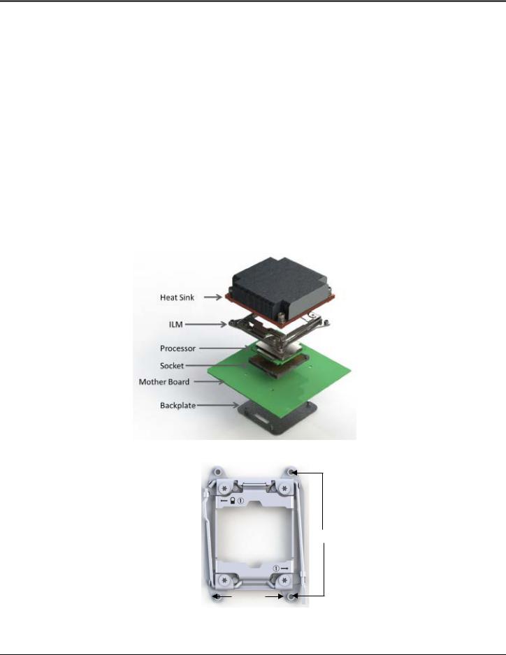
Intel® Server Board S2600WT TPS
3.Processor Support
The server board includes two Socket-R3 (LGA2011-3) processor sockets and can support one or two of the following processors:
Intel® Xeon® processor E5-2600 v3 product family
Supported Thermal Design Power (TDP) of up to 145W.
Note: Previous generation Intel® Xeon® processors are not supported on the Intel server boards described in this document.
Visit http://www.intel.com/support for a complete list of supported processors.
3.1Processor Socket Assembly
Each processor socket of the server board is pre-assembled with an Independent Latching Mechanism (ILM) and Back Plate which allow for secure placement of the processor and processor heat sink to the server board.
The illustration below identifies each sub-assembly component:
Figure 7. Processor Socket Assembly
94 mm
56 mm
Figure 8. LGA2011-3 ILM (Narrow)
Revision 1.0 |
14 |

Intel® Server Board S2600WT TPS
3.2Processor Thermal Design Power (TDP) Support
To allow optimal operation and long-term reliability of Intel processor-based systems, the processor must remain within the defined minimum and maximum case temperature (TCASE) specifications. Thermal solutions not designed to provide sufficient thermal capability may affect the long-term reliability of the processor and system. The server board described in this document is designed to support the Intel® Xeon® Processor E52600 v3 product family TDP guidelines up to and including 145W.
Disclaimer Note: Intel Corporation server boards contain a number of high-density VLSI and power delivery components that need adequate airflow to cool. Intel ensures through its own chassis development and testing that when Intel server building blocks are used together, the fully integrated system will meet the intended thermal requirements of these components. It is the responsibility of the system integrator who chooses not to use Intel developed server building blocks to consult vendor datasheets and operating parameters to determine the amount of airflow required for their specific application and environmental conditions. Intel Corporation cannot be held responsible if components fail or the server board does not operate correctly when used outside any of its published operating or non-operating limits.
3.3Processor Population Rules
Note: The server board may support dual-processor configurations consisting of different processors that meet the defined criteria below, however, Intel does not perform validation testing of this configuration. In addition, Intel does not guarantee that a server system configured with unmatched processors will operate reliably. The system BIOS will attempt to operate with processors which are not matched but are generally compatible.
For optimal system performance in dual-processor configurations, Intel recommends that identical processors be installed.
When using a single processor configuration, the processor must be installed into the processor socket labeled “CPU_1”.
Note: Some board features may not be functional without having a second processor installed. See Figure 6. Intel® Server Board S2600WT Architectural Block Diagram.
When two processors are installed, the following population rules apply:
Both processors must be of the same processor family
Both processors must have the same number of cores
Both processors must have the same cache sizes for all levels of processor cache memory
Processors with different core frequencies can be mixed in a system, given the prior rules are met. If this condition is detected, all processor core frequencies are set to the lowest common denominator (highest common speed) and an error is reported.
Processors which have different Intel® Quickpath (QPI) Link Frequencies may operate together if they are otherwise compatible and if a common link frequency can be selected. The common link frequency would be the highest link frequency that all installed processors can achieve.
Processor stepping within a common processor family can be mixed as long as it is listed in the processor specification updates published by Intel Corporation. Mixing of steppings is only validated and supported between processors that are plus or minus one stepping from each other.
15 |
Revision 1.0 |

Intel® Server Board S2600WT TPS
3.4Processor Initialization Error Summary
The following table describes mixed processor conditions and recommended actions for all Intel® server boards and Intel server systems designed around the Intel® Xeon® processor E5-2600 v3 product family and Intel® C612 chipset architecture. The errors fall into one of the following categories:
Fatal: If the system can boot, POST will halt and display the following message:
“Unrecoverable fatal error found. System will not boot until the error is resolved Press <F2> to enter setup”
When the <F2> key on the keyboard is pressed, the error message is displayed on the Error Manager screen, and an error is logged to the System Event Log (SEL) with the POST Error Code.
This operation will occur regardless of whether the BIOS Setup option “Post Error Pause” is set to Enable or Disable.
If the system is not able to boot, the system will generate a beep code consisting of 3 long beeps and 1 short beep. The system cannot boot unless the error is resolved. The faulty component must be replaced.
The System Status LED will be set to a steady Amber color for all Fatal Errors that are detected during processor initialization. A steady Amber System Status LED indicates that an unrecoverable system failure condition has occurred.
Major: If the BIOS Setup option for “Post Error Pause” is Enabled, and a Major error is detected, the system will go directly to the Error Manager screen in BIOS Setup to display the error, and logs the POST Error Code to SEL. Operator intervention is required to continue booting the system.
If the BIOS Setup option for “POST Error Pause” is Disabled, and a Major error is detected, the Post Error will be logged to the BIOS Setup Error Manager, an error event will be logged to the System Event Log (SEL), and the system will continue to boot.
Minor: An error message may be displayed to the screen or to the BIOS Setup Error Manager, and the POST Error Code is logged to the SEL. The system continues booting in a degraded state. The user may want to replace the erroneous unit. The POST Error Pause option setting in the BIOS setup does not have any effect on this error.
Table 3. Mixed Processor Configurations Error Summary
Error |
Severity |
System Action |
|
|
|
|
|
|
|
The BIOS detects the error condition and responds as follows: |
|
|
|
Halts at POST Code 0xE6. |
|
Processor family not Identical |
Fatal |
Halts with 3 long beeps and 1 short beep. |
|
|
|
Takes Fatal Error action (see above) and will not boot until the fault condition is |
|
|
|
remedied. |
|
|
|
|
|
|
|
The BIOS detects the error condition and responds as follows: |
|
|
|
Logs the POST Error Code into the System Event Log (SEL). |
|
Processor model not Identical |
Fatal |
Alerts the BMC to set the System Status LED to steady Amber. |
|
Displays “0196: Processor model mismatch detected” message in the Error Manager. |
|||
|
|
||
|
|
Takes Fatal Error action (see above) and will not boot until the fault condition is |
|
|
|
remedied. |
|
|
|
|
Revision 1.0 |
16 |
Loading...