How it Works
Log In / Sign Up
Buy Points
How it Works
FAQ
Contact Us
Questions and Suggestions
Users
Intel
Loading...
#
633ANHMWWB
633ANHU
2
640 - Pentium 4 640 3.2GHz 800MHz 2MB Socket 775 CPU
6700PXH
6700PXH 64-BIT PCI HUB - MECHANICAL DESIGN
6910P
695AS
7075A
7260H
4
7260.HMWANWB
7260HMWBNWB
7260HMWDTX1
7260HMWG
7260HMWNBWB
7260.HMWWB
7260HU
4
7260NA
7260NG
3
7260NGU
3
7260SD
7262W2
7262WW
7265D2
3
7265NG
2
7265NGU
2
7272NA
760p series
7 Joi
7xx
80188EB
80386 DX
80386EX (386EX)
80960HA
80960HD
2
80960HT
2
80960JD
80960KB
80960MC
80960RD (i960® RD I/O Processor)
2
80960SA
80C186EA
4
80C186EB
2
80C186EC
3
80C186XL
2
80C188EA
5
80C188EB
3
80C188EC
3
80C188XL
3
80C196KB Series
80c196kc
80c196kc20
80C196NU
80C51FA
80L186EA
4
80L186EB
3
80L186EC
2
80L188EA
4
80L188EB
3
80L188EC
2
740
800
2
810A3
810-DC100 (Whitney)
810 (Whitney)
811
813
815
2
7190
7200
7400
7500
7510
7512
8008
8051
8080
4
8085
3
8086
8153
810E2
8155H
8155H-2
8156H
8156H-2
8 LAN
80200
80219
80286
80287
2
80302
80303
80331
80386
3
8086-1
2
8086-2
2
81341
81342
654655-001
747116-011
754458-002
Loading...
Loading...
Nothing found
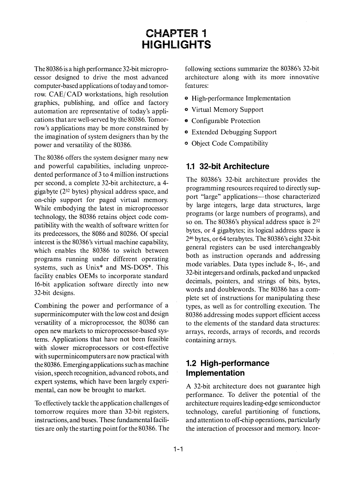
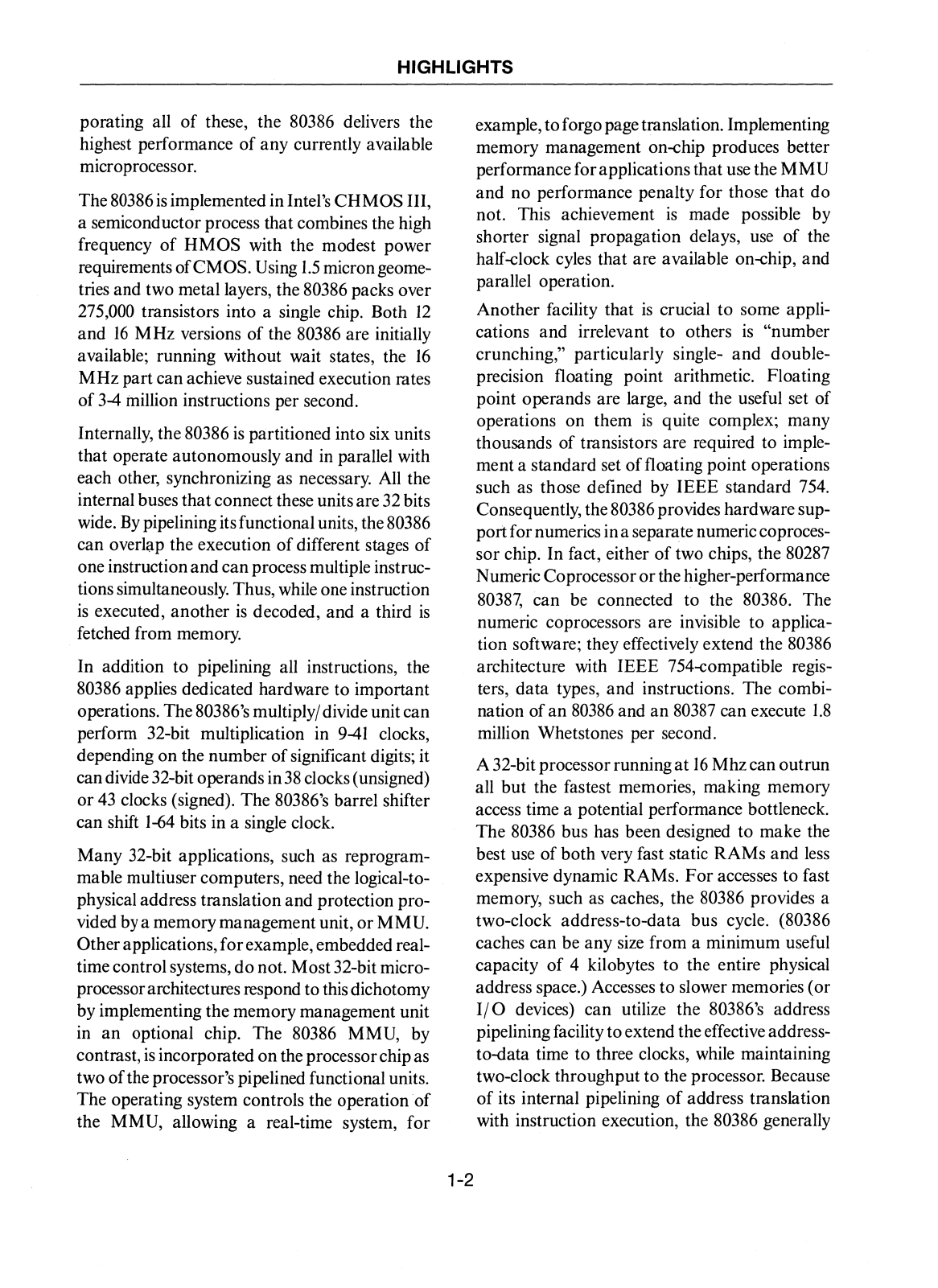
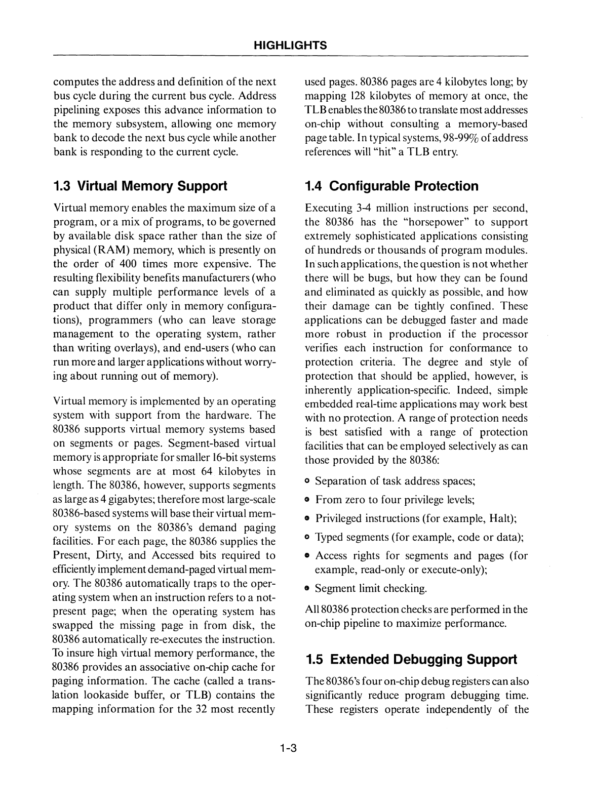
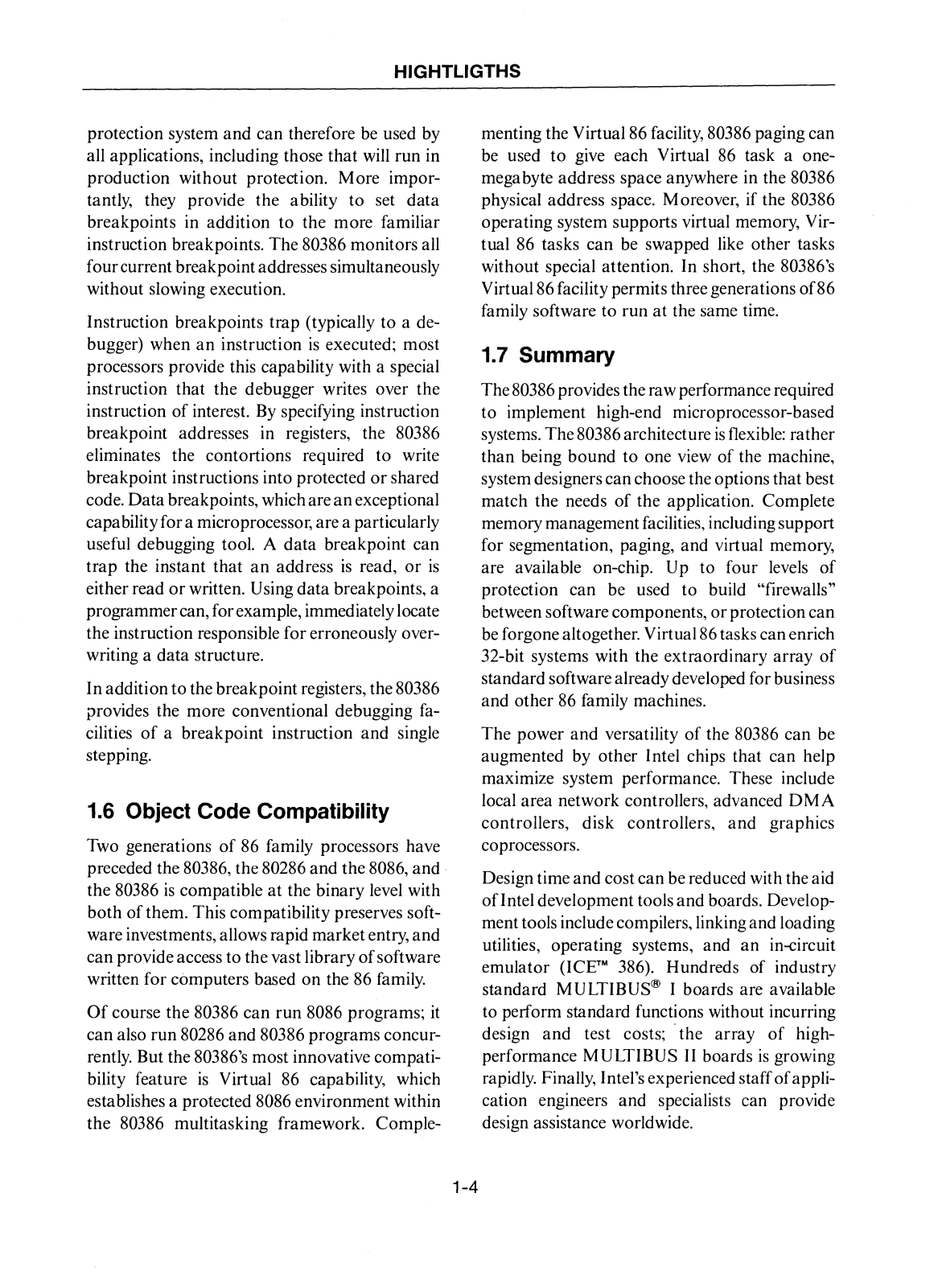
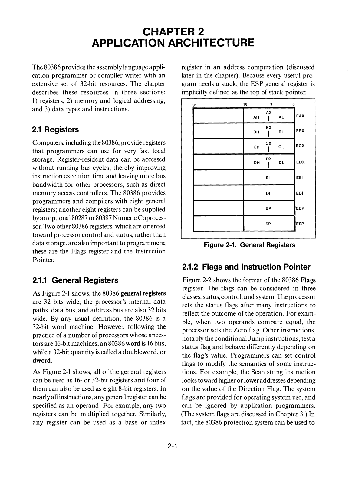
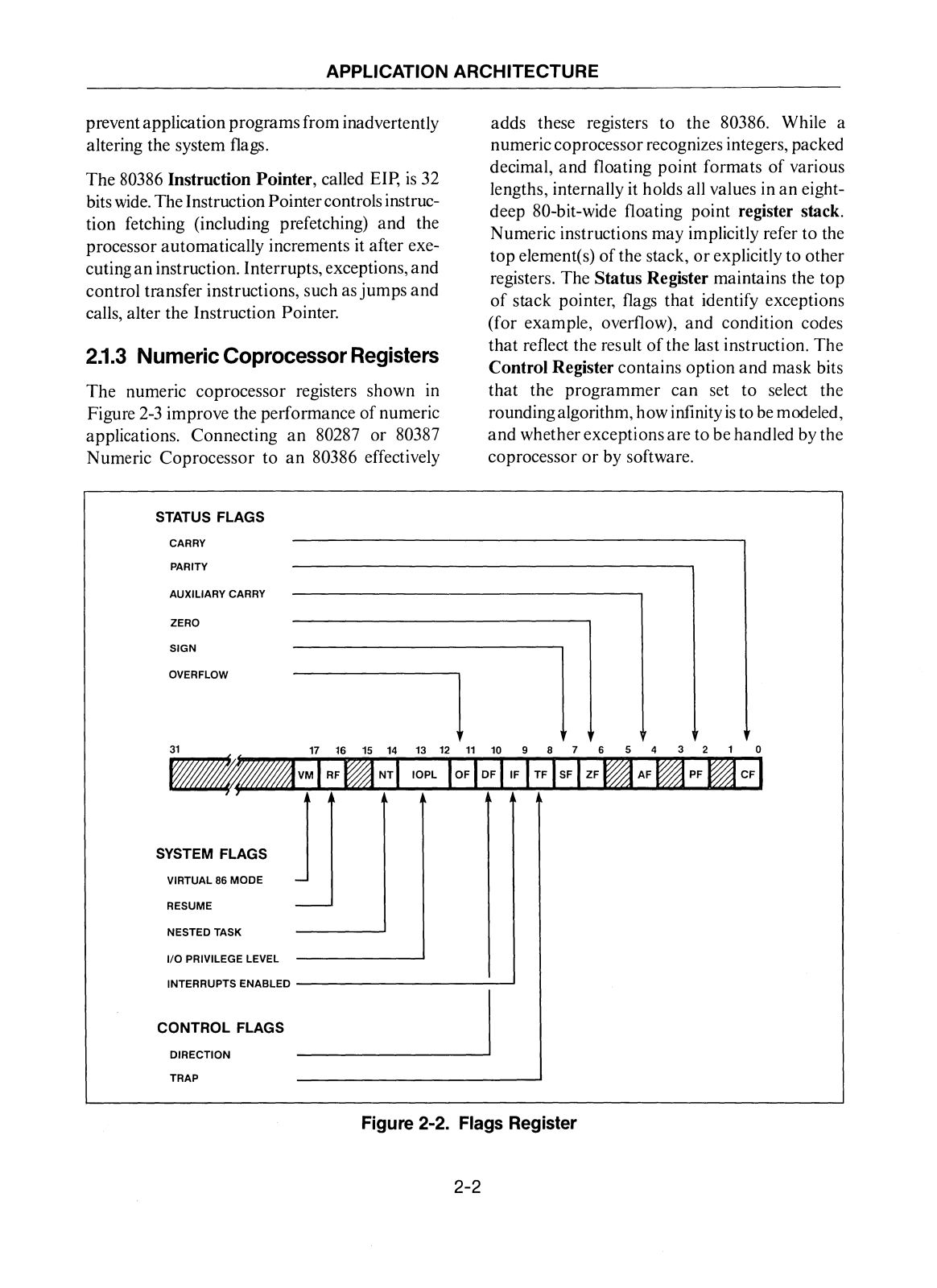
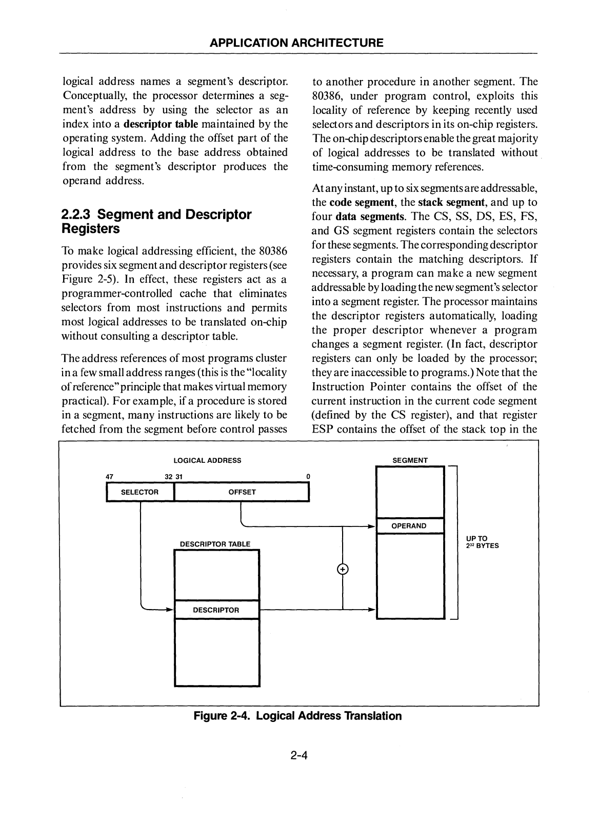
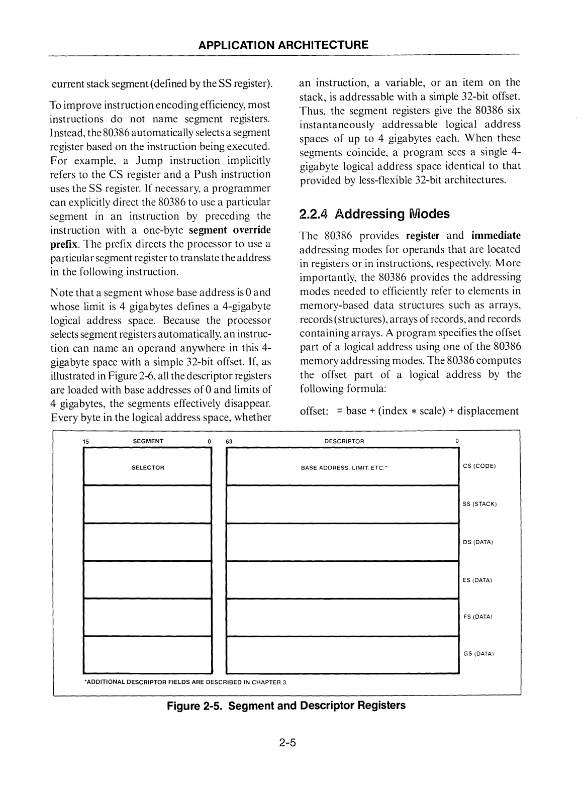
80386
Hardware Reference Manual
308 pgs
14.73 Mb
0
Reference Manual
291 pgs
14.48 Mb
0
User Manual
194 pgs
12.9 Mb
0
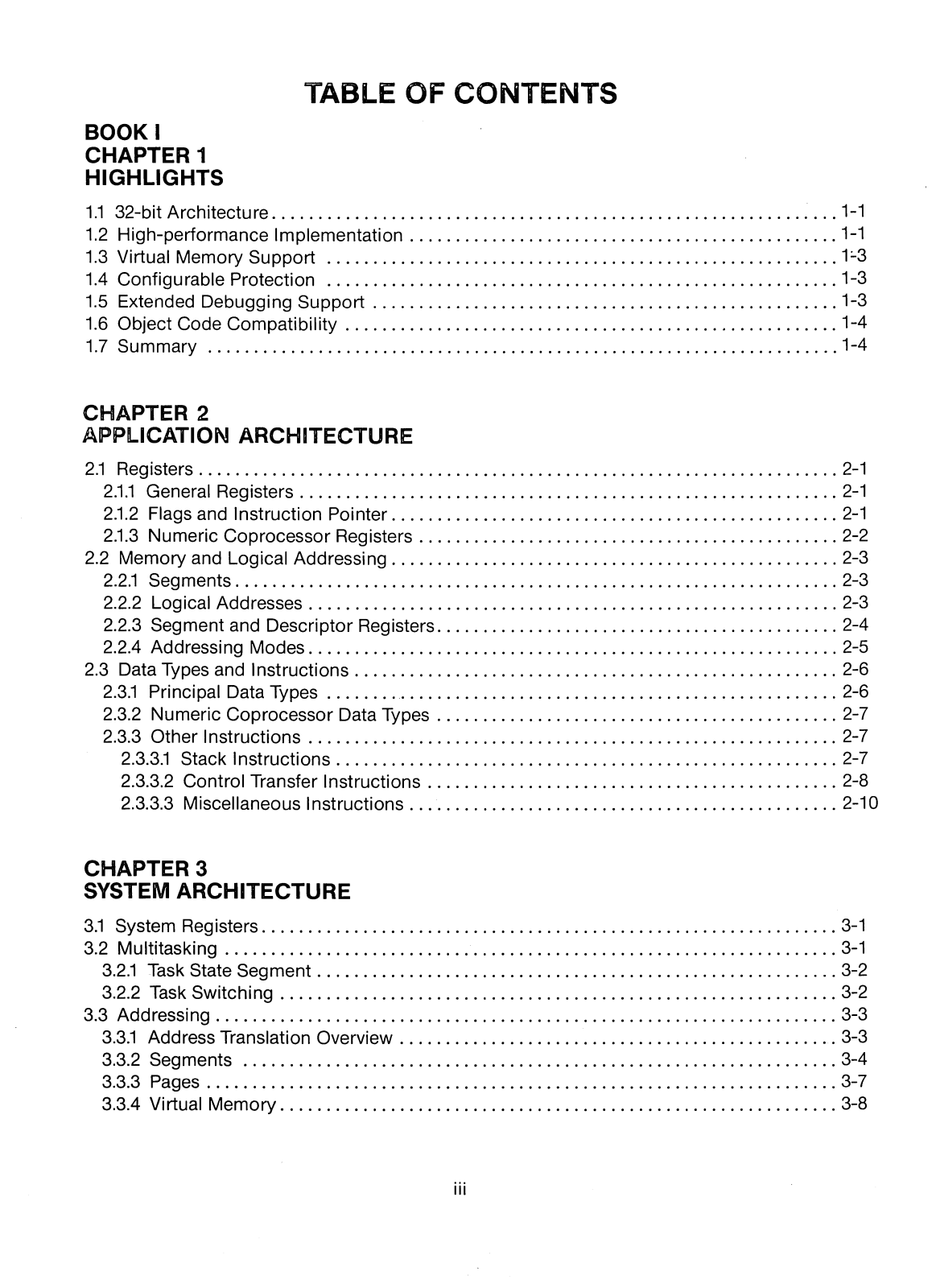
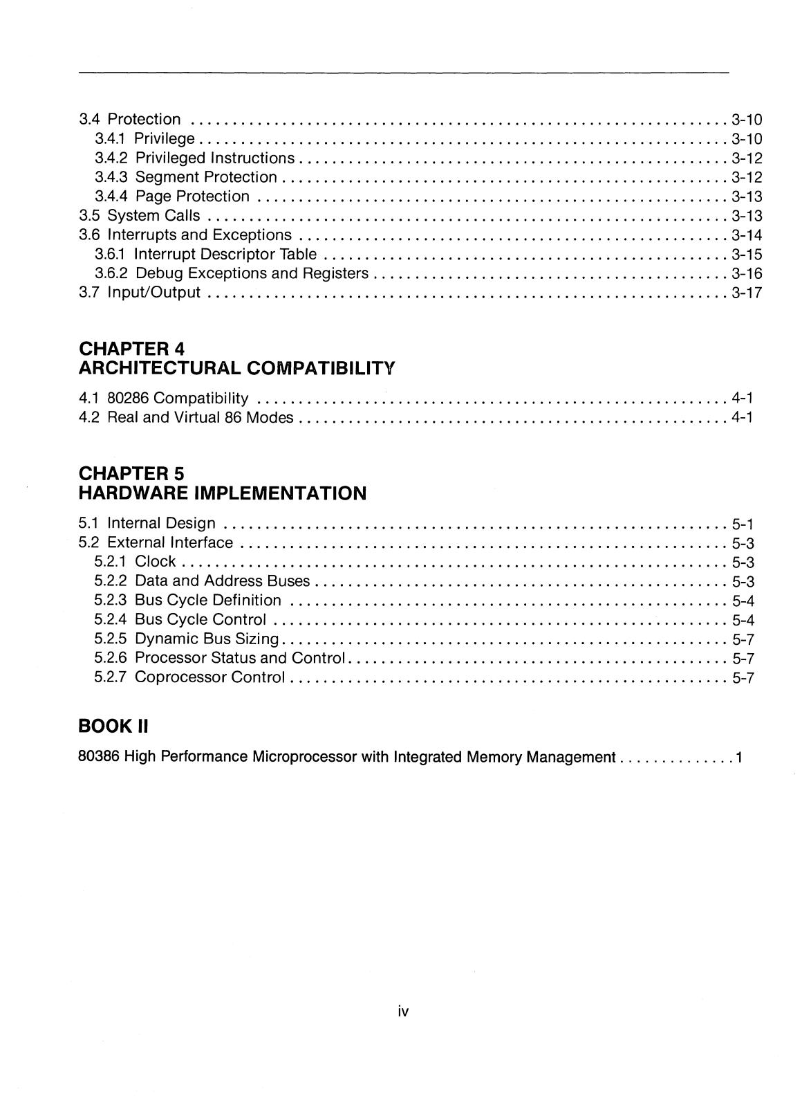
Table of contents
Loading...
Intel 80386 User Manual
...
Intel User Manual
Download
Specifications and Main Features
Frequently Asked Questions
User Manual
Download
Loading...
+
hidden pages
Unhide
You need points to download manuals.
1 point = 1 manual.
You can buy points or you can get point for every manual you upload.
Buy points
Upload your manuals
 Loading...