


Ingersoll Rand
X41 System Automation
Operator’s Manual
Before installing or starting this unit for the first time, this manual should be studied carefully to obtain a working knowledge of the unit and/or the duties to be performed while operating and maintaining the unit.
RETAIN THIS MANUAL WITH UNIT. This Technical manual contains IMPORTANT SAFETY DATA and should be kept with the unit at all times.
More Than Air. Answers.
Online answers: http://www.air.irco.com
C.C.N. : 80443617 REV. : A
DATE : APRIL 2007
1

SECTION 1 — TABLE OF CONTENTS
SECTION 1 — TABLE OF CONTENTS................................ |
2 |
SECTION 2 — INTRODUCTION........................................ |
4 |
SECTION 3 — SAFETY..................................................... |
4 |
INSTALLATION ............................................................ |
4 |
OPERATION................................................................. |
4 |
MAINTENANCE AND REPAIR ........................................ |
5 |
SECTION 4 — COMPRESSOR CONNECTION & CONTROL.. 6 |
|
PRESSURE DETECTION AND CONTROL......................... |
6 |
SECTION 5 — DISPLAY AND MENU OPERATION .............. |
7 |
DISPLAY ITEM STRUCTURE .......................................... |
9 |
NORMAL OPERATIONAL DISPLAY (MENU PAGE P00)..... |
9 |
INFORMATION DISPLAYS ............................................. |
9 |
Status Display.......................................................... |
9 |
Sequence Rotation................................................. |
10 |
OPERATIONAL FUNCTIONS........................................ |
11 |
STOP ..................................................................... |
11 |
START ................................................................... |
11 |
POWER FAILURE AUTO-RESTART ............................ |
11 |
FAILURE MODE....................................................... |
11 |
RESET .................................................................... |
11 |
SECTION 6 — CONTROL FEATURES AND FUNCTIONS.... |
12 |
STANDARD CONTROL FEATURES AND FUNCTIONS.... |
12 |
PRESSURE CONTROL .............................................. |
12 |
ANTI-CYCLING CONTROL....................................... |
13 |
TOLERANCE........................................................... |
13 |
DAMPING............................................................... |
13 |
SYSTEM VOLUME ................................................... |
14 |
STANDARD SEQUENCE CONTROL STRATEGY.......... |
15 |
FIRST IN LAST OUT MODE (FILO) ............................ |
15 |
SEQUENCE ROTATION EVENTS ............................... |
15 |
ADVANCED CONTROL FEATURES AND FUNCTIONS ... |
16 |
ADVANCED SEQUENCE CONTROL STRATEGIES ....... |
16 |
Variable Energy Control Mode (VEC) ...................... |
16 |
Priority Settings..................................................... |
16 |
Tables and the Pressure Schedule.......................... |
17 |
Pressure Schedule ................................................. |
18 |
Pre-fill.................................................................... |
18 |
ALTERNATE CONTROL FEATURES AND FUNCTIONS ... |
20 |
Equal Hours Run Mode .......................................... |
20 |
First In First Out Mode (FIFO)................................. |
20 |
SECTION 7 — INSTALLATION ........................................ |
22 |
Unit Location ............................................................. |
22 |
Power Supply............................................................. |
22 |
Pressure Sensor Location........................................... |
22 |
Generation Side Pressure Control ........................... |
22 |
System (Demand Side) Pressure Control ................. |
23 |
Pressure Sensor Connection ...................................... |
23 |
IR-PCB Interface Module............................................. |
23 |
Input Functions ......................................................... |
24 |
Ready Input ............................................................ |
24 |
Ready Input, Alternative Connection Method.......... |
25 |
Run Input ............................................................... |
26 |
Warning Input (optional)......................................... |
27 |
Output Functions....................................................... |
27 |
Pressure Switch Regulation..................................... |
28 |
Digital Regulation Control Terminal C01 ................ |
29 |
Service Maintenance Switch .................................... |
30 |
Auxiliary Input (Option).......................................... |
30 |
Auxiliary Output (Option) ....................................... |
31 |
RS485 Communications ......................................... |
31 |
SECTION 8 — FAULT CODES.......................................... |
32 |
X4I Compressor Fault Indications, Types, and Codes:32 |
|
Alarm (Warning) ..................................................... |
32 |
Not Available.......................................................... |
32 |
Compressor Inhibited, Removed From Service........ |
33 |
Service/Maintenance .............................................. |
33 |
Communications Disruption................................... |
33 |
Special Controller Fault Codes................................ |
33 |
Error Log ................................................................ |
33 |
SECTION 9 — Commissioning....................................... |
35 |
Physical Checks ......................................................... |
35 |
Pressure Display ........................................................ |
35 |
X4I Quick Set-up Configuration.................................. |
35 |
SECTION 10 — System Configuration............................ |
36 |
Accessing the X4I Configuration Screens ................... |
36 |
User Configuration: Tab S01...................................... |
37 |
Real Time Clock Settings ........................................ |
37 |
Pressure Schedule Settings..................................... |
38 |
Auto Restart Settings.............................................. |
39 |
Rotation Interval Settings ....................................... |
40 |
2
Table Select Settings ............................................. |
41 |
Backlight Adjust Settings....................................... |
42 |
User Configuration: Tab S02..................................... |
42 |
Units Settings ........................................................ |
43 |
Number of Compressors Settings .......................... |
43 |
Maximum Pressure Alarm Settings ........................ |
44 |
Stop Control Settings............................................. |
45 |
Tolerance Settings................................................. |
46 |
Damping Settings.................................................. |
47 |
Pressure Change Settings ...................................... |
47 |
Auxiliary Input Settings ......................................... |
48 |
Auxiliary Output Settings ...................................... |
49 |
Error Log Reset...................................................... |
50 |
User Configuration: Tab S03..................................... |
50 |
Pressure Sensor – Offset........................................ |
51 |
Pressure Sensor – Range Settings .......................... |
51 |
Compressor Configuration: Tab C01 ........................ |
52 |
Compressor Run Hours ......................................... |
53 |
Compressor Configuration: Tab C02 ........................ |
53 |
Compressor Connection Method ........................... |
54 |
Compressor Table Configuration: Tab T01 ............... |
57 |
High Pressure Setpoint Settings............................. |
57 |
Low Pressure Setpoint Settings.............................. |
58 |
Minimum Pressure Alarm Settings .......................... |
58 |
Sequence Strategy Settings..................................... |
59 |
Compressor #1 Priority Settings ............................. |
60 |
Compressor #2 through 4 Priority Settings............. |
60 |
Pressure Schedule Configuration P01 Tab Screen ...... |
61 |
Pressure Schedule Settings..................................... |
61 |
Pre-fill Configuration P02 Tab Screen ..................... |
62 |
Pre-fill Function Settings......................................... |
63 |
Pre-fill Time Settings .............................................. |
64 |
Pre-fill Pressure Settings......................................... |
65 |
Pre-fill Compressor #1 Settings .............................. |
65 |
Pre-fill Compressor #2 through 4 Settings.............. |
66 |
Diagnostics D01 Tab Screen ...................................... |
67 |
Diagnostics Settings............................................... |
67 |
X4I Controller Diagnostics...................................... |
68 |
Digital Inputs ......................................................... |
68 |
Relay Outputs......................................................... |
68 |
Analog Inputs......................................................... |
69 |
Analog Output........................................................ |
69 |
Total Unit Reset and Default Values........................ |
69 |
Parts List....................................................................... |
73 |
Technical Data.............................................................. |
74 |
Diagrams...................................................................... |
75 |
3
SECTION 2 — INTRODUCTION
The X4I is a specialized controller designed to provide safe, reliable, and energy-efficient control of your compressed air system. The X4I is capable of controlling up to four positive displacement air compressors. The compressors may have electro-pneumatic or microprocessor based controls. The X4I is completely customizable to meet the specific needs of your compressed air system.
SECTION 3 — SAFETY
!WARNING : Risk of Danger
WARNING : Risk of Electric Shock
! |
WARNING : Risk of High Pressure |
|
WARNING : Consult Manual
•Before installing or operating the X4I, take time to carefully read all the instructions contained in this manual, all compressor manuals, and all manuals of any other peripheral devices that may be installed or connected to the unit.
•Electricity and compressed air have the potential to cause severe personal injury or property damage.
•The operator should use common sense and good working practices while operating and maintaining this system. All applicable codes should be strictly adhered to.
•Maintenance must be performed by adequately qualified personnel that are equipped with the proper tools.
INSTALLATION
•Installation work must only be carried out by a competent person under qualified supervision.
•A fused isolation switch must be fitted between the main power supply and the X4I.
•The X4I should be mounted in such a location as to allow operational and maintenance access without obstruction or hazard and to allow clear visibility of indicators at all times.
•If raised platforms are required to provide access to the X4I, they must not interfere with normal operation or obstruct access. Platforms and stairs should be of grid or plate construction with safety rails on all open sides.
OPERATION
•The X4I must only be operated by competent personnel under qualified supervision.
•Never remove or tamper with safety devices, guards or insulation materials fitted to the X4I.
•The X4I must only be operated at the supply voltage and frequency for which it is designed.
•When main power is switched on, lethal voltages are present in the electrical circuits and extreme caution must be exercised whenever it is necessary to carry out any work on the unit.
•Do not open access panels or touch electrical components while voltage is applied unless it is necessary for measurements, tests or adjustments. Such work should be carried out only by a qualified electrician equipped with the correct tools and wearing appropriate protection against electrical hazards.
•All air compressors and/or other equipment connected to the unit should have a warning sign attached stating “THIS UNIT MAY START WITHOUT WARNING” next to the display panel.
•If an air compressor and/or other equipment connected to the unit is to be started remotely, attach two warning signs to the equipment stating “THIS UNIT CAN BE STARTED REMOTELY”. Attach one sign in a
4

prominent location on the outside of the equipment, and the other sign inside the equipment control compartment.
MAINTENANCE AND REPAIR
•Maintenance, repairs or modifications must only be carried out by competent personnel under qualified supervision.
•If replacement parts are required, use only genuine parts from the original equipment manufacturer, or an alternative approved source.
•Carry out the following operations before opening or removing any access panels or carrying out any work on the X4I:
i.Isolate the X4I from the main electrical power supply. Lock the isolator in the “OFF” position and remove the fuses.
ii.Attach labels to the isolator switch and to the unit stating “WORK IN PROGRESS - DO NOT APPLY VOLTAGE”. Do not switch on electrical power or attempt to start the X4I if such a warning label is attached.
•Make sure that all instructions concerning operation and maintenance are strictly followed and that the complete unit, with all accessories and safety devices, is kept in good working order.
•The accuracy of sensor devices must be checked on a regular basis. They must be calibrated when acceptable tolerances are exceeded. Always ensure any pressure within the compressed air system is safely vented to atmosphere before attempting to remove or install a sensor device.
•The X4I must only be cleaned with a damp cloth, using mild detergents if necessary. Avoid the use of any substances containing corrosive acids or alkalis.
•Do not paint the control faceplate or obscure any indicators, controls, instructions or warnings.
5
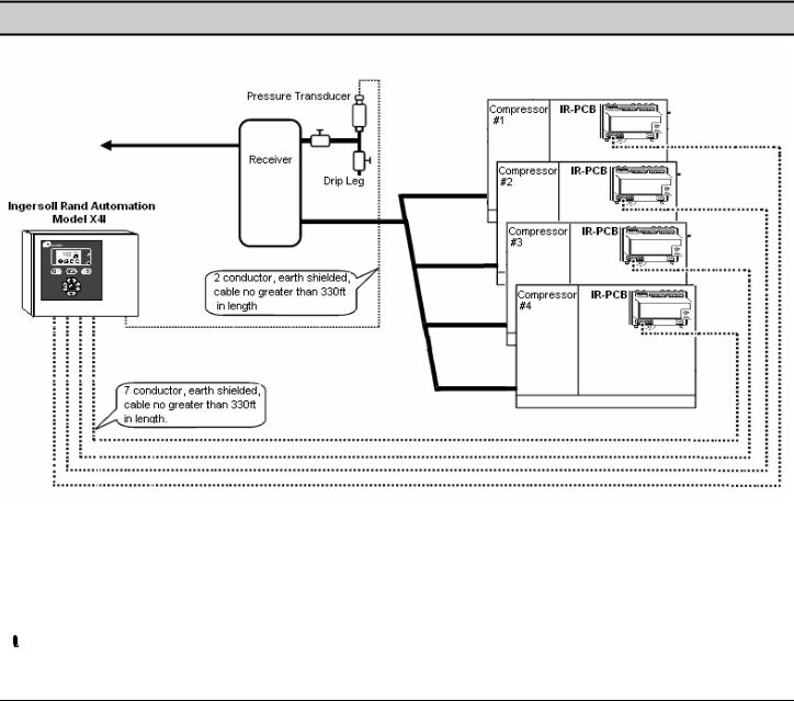
SECTION 4 — COMPRESSOR CONNECTION AND CONTROL
Each air compressor in your system can be interfaced to the X4I using the included IR-PCB interface modules. Any compressor with an available control voltage of 12-250V (either 50Hz or 60Hz) can be controlled by the X4I.
The interface module is mounted inside the compressor’s starter panel and connected to the X4I by using a shielded 7- conductor cable, or individual cables run through conduit.
Each air compressor must be equipped with an online/offline pressure regulation system capable of accepting a remote load/unload signal through a volt-free switching contact or a single electro-mechanical pressure switch.
 Consult the air compressor manual or your air compressor supplier/specialist for details before installing the X4I.
PRESSURE DETECTION AND CONTROL
The X4I utilizes the signal from a 4-20 ma pressure sensor that is mounted remotely from the X4I in a suitable location in the compressed air system.
The factory default settings for the pressure sensor is 0–232 PSI (16 bar), but the X4I can accept any pressure sensor with a 4–20 ma output and a range of up to 8700 PSI (600 bar).
6
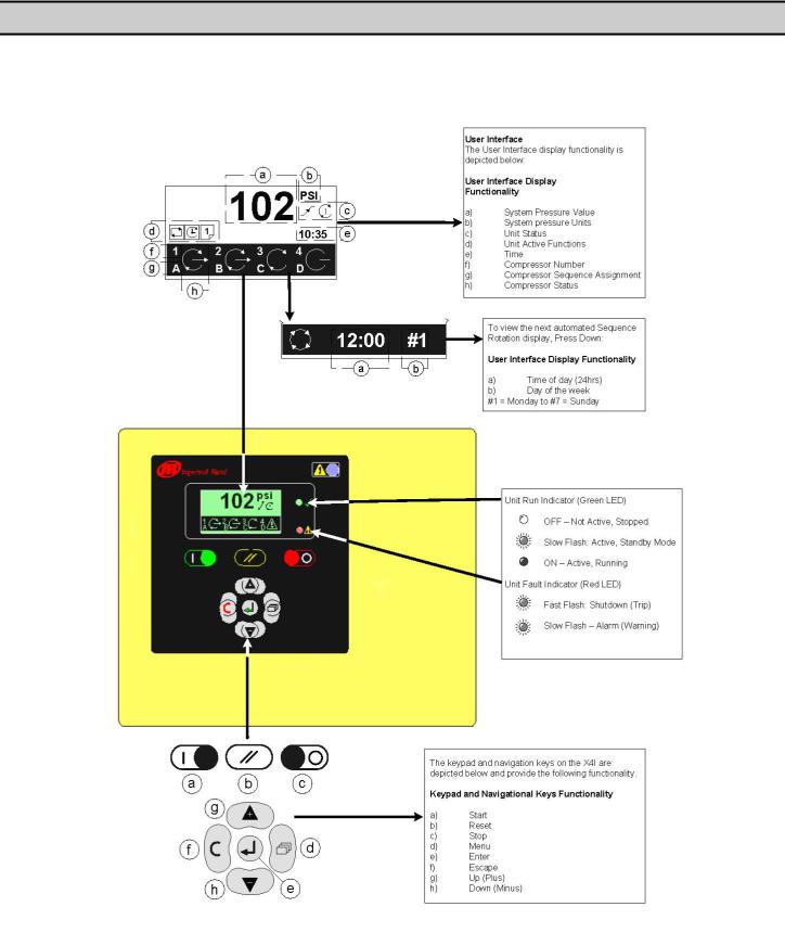
SECTION 5 — DISPLAY AND MENU OPERATION
The Main Display and the keypad and navigation buttons on the X4I are depicted below and provide the following functionality:
7

8
DISPLAY ITEM STRUCTURE
Operational system status and values are accessible from the normal user display. To view status or values that are not normally visible on the default screen, press UP or DOWN. All standard user display items are viewable only and cannot be adjusted. The standard user display items are regarded as “Menu Page 00” items.
All adjustable value, parameter or option item displays are grouped into “menu mode” lists. Items are assigned to a list according to type and classification. Item lists are identified by page number (or menu number). All adjustable parameters and options are assigned to menu mode pages “P01” or higher.
NORMAL OPERATIONAL DISPLAY (MENU PAGE P00)
At controller initialization, all display elements and LED indicators are switched on for three seconds. The display will then show the software version code for a further three seconds before initialization is complete and the normal operating display (“Page P00”) is shown. In normal operational display mode, the main display will continuously show the detected system pressure and the Item display will show the first item of the “Page 00” menu. User menu “items” can be selected using the UP or DOWN buttons at any time. Pressing the ENTER button will lock any selected item display and inhibit return to the default display. When an item display is locked, the “lock key” symbol will be shown. To unlock an item display, press UP or DOWN to view an alternative item display or press RESET or ESCAPE. No item values, options or parameters can be adjusted in “Page P00”. If a fault condition occurs, the fault code becomes the first list item and the display will automatically jump to display the fault code. More than one active fault code item can exist at any one time and can be viewed by pressing UP or DOWN. The most recent “active” fault will be at the top of the list.
Main Status Screen
INFORMATION DISPLAYS
To view detailed information applicable to the selected User menu display item press the ENTER  button:
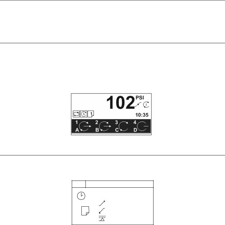
STATUS DISPLAY
P00
#1 18:00 T02
1 |
102 |
psi |
98 |
psi |
|
|
80 |
psi |
Status Display Screen
9
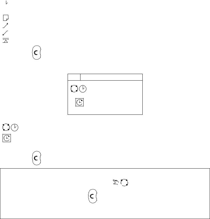
 If the ‘Pressure Schedule’ feature is active; shows the day of the week (#1), the time of day (18:00) and the table to be used (T02) of the next scheduled instruction to be executed.
1 |
The current active ‘Table’ (T01) |
Upper, or unload, pressure setpoint
Lower, or load, pressure setpoint
Minimum pressure Alarm (Warning)
Press the ESCAPE  button to return to the normal operational display screen.
SEQUENCE ROTATION
P00
|
#4 |
18:00 |
|
18 / 05 / 2006 |
|
|
A B C D |
|
|
Sequence Rotation Display Screen |
|
|
Day of the week (#4: Thursday), the time of day (18:00) and the date (18/05/2006) of the next automated |
|
|
sequence rotation event. |
|
|
The active ‘mode’ of operation |
|
ABCD |
The current active rotation sequence assignment. |
|
Press the ESCAPE  button to return to the normal operational display screen.
NOTE: The sequence assignment can be manually rotated at any time. When viewing the “Sequence Rotation” information
screen press the ENTER button. The manual rotation symbols
  will appear and flash. Press the ENTER
button to execute a manual rotation or the ESCAPE  button to abandon the manual rotation.
Automated sequence rotation is not disrupted by a manual rotation; the next scheduled automated sequence rotation event will still occur.
10
OPERATIONAL FUNCTIONS
STOP 
To stop the X4I, press STOP. Dependent on the setup and configuration of the X4I, the compressors will function as follows:
•If parameter PC=0, then pressure regulation control is automatically transferred back to each compressor. The compressor(s) will continue to operate using the pressure settings programmed or set in the individual compressor controller(s).
•If parameter PC=1, then the X4I will hold each compressor in an offload state. If the compressor is equipped with a main motor run-on-time function, the compressor will run offload for a period of time and then stop into a “standby” or “auto restart” state.
 The design of some air compressor control systems may inhibit automatic transfer of pressure regulation control to local operation mode. In this instance, the compressor will not continue production of compressed air. Consult the air compressor manual or your air compressor supplier/specialist for details before installing the X4I.
START 
To start the X4I, press START. If the pre-fill function is enabled, and system pressure is below the set pre-fill pressure, the system will enter pre-fill mode for the set pre-fill time.
 See the section on pre-fill for more information.
 To manually skip the pre-fill function, press and hold START for several seconds. When pre-fill is complete, if applicable, the X4I will enter normal operating mode. The X4I will operate in accordance with the parameters and options set in the active “table”.
 See the section on tables for more information.
 Each compressor in the system must be started (running or in a standby or auto restart condition) before X4I control of the compressor can be established. The X4I will not start a compressor that is in a stopped condition.
POWER FAILURE AUTO-RESTART 
If the power failure auto-restart function is enabled, the X4I will automatically start when power is restored after a disruption or failure, if the X4I was in a “started” state when the power disruption or failure occurred.
NOTE: The X4I will not automatically restart if the X4I was in a stopped state when the power disruption or failure occurred.
FAILURE MODE
If the X4I experiences a disruption to normal control, or an X4I shutdown fault occurs, pressure regulation control is automatically transferred back to each compressor. The compressor(s) will continue to operate using the pressure settings programmed or set in the individual compressor controller(s).
RESET 
To reset an X4I alarm (warning) or shutdown condition, press RESET. Compressor alarm (warning) conditions are automatically reset when the condition has been resolved and reset on the compressor. “Compressor not available” (shutdown, trip) conditions are automatically reset when the condition has been resolved and reset on the compressor and the compressor has been restarted.
11
SECTION 6 — CONTROL FEATURES AND FUNCTIONS
STANDARD CONTROL FEATURES AND FUNCTIONS
PRESSURE CONTROL
Pressure control is achieved by maintaining the system pressure within an acceptable range, or pressure band, which is defined and programmed by the user. Pressure will rise in the band when system demand is less than the loaded compressor’s output. Pressure will fall in the band when system demand is greater than the loaded compressor’s output.
Simply stated, pressure control is achieved by unloading and loading compressors to closely match compressor output with system demand within a specified pressure band.
Variable speed compressors also operate within the pressure band and actively match compressor output with demand by speeding up and slowing down around a target pressure defined by the exact midpoint of the pressure band.
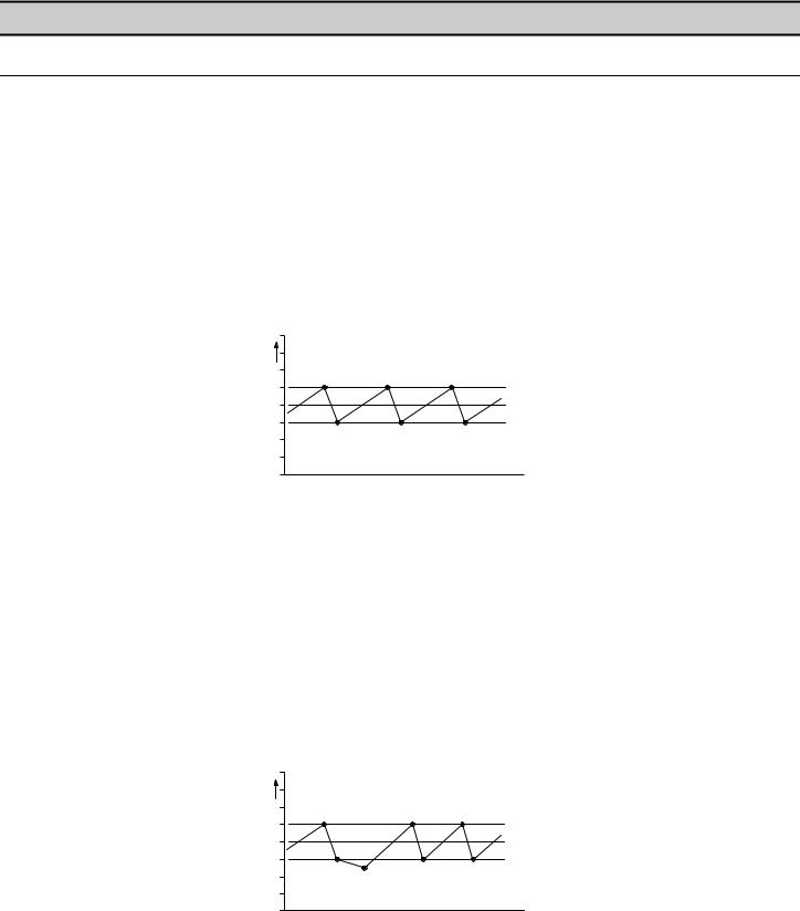
Refer to the illustration below. The X4I functions by keeping the system pressure inside of an acceptable pressure range defined by the user. Compressors will load and unload in order to keep the pressure between the high pressure setpoint (PH) and the low pressure setpoint (PL), both of which are user adjustable. The pressure control algorithms will attempt to keep the pressure toward the midpoint of this pressure band. This midpoint is known as the system target pressure (PT).
a |
PH |
PT |
PL |
b |
Typical System Pressure vs. Time
As pressure rises to point “a”, the compressor will unload based on the sequencing algorithm. System pressure is then allowed to decrease due to the drop in supply until point “b” is reached. Once point “b” is reached, the X4I will load the next compressor in the sequence to match the air demand. This cycle will repeat as long as the X4I is able to keep the system air pressure between PH and PL.
When a compressed air system includes one or more variable speed compressors, each variable speed compressor must have its target pressure (on its local controller) set to the system target pressure.
The variable speed compressors in the system will run on their target pressure and smooth out the variations in system pressure. This assumes that system demand does not vary more than the capacity of the variable speed compressor.
A variable speed compressor will be included in the load/unload sequence and be controlled exactly as a fixed speed machine with the exception of speed control to maintain target pressure.
Refer to the illustration below. If the system demand increases significantly or quickly and the capacity of the loaded compressor is insufficient to meet the demand, the system pressure will continue to decline at a slower rate. The X4I will then calculate the instant at which the next compressor is to be loaded. This instant, at point “c”, is dependent on the rate of change of the system pressure and the user adjustable anti-cycling control settings.
a |
PH |
|
|
||
|
PT |
|
b |
PL |
|
c |
||
|
Compressor Supply is Insufficient to Maintain System Pressure
The same logic will come into effect if the system pressure rises above the PH setpoint due to a significant or abrupt reduction in demand.
12

There are many variables that go into determining the stability and control of the system pressure, only some of which are able to be controlled by the X4I. System storage, air compressor capacity, and air demand all need to be analyzed by experienced professionals to determine the best installation for your system. Tolerance (TO) and damping (DA) can be used for minor tuning of the system.
ANTI-CYCLING CONTROL
The most efficient way to utilize most air compressors is either fully loaded or off, with the exception of variable speed compressors which can operate efficiently at reduced loading. Compressor cycling (start-load-unload-stop, etc.) is essential to maintain pressure control. Excessive cycling, however, can result in poor compressor efficiency as well as increased maintenance.
Anti-cycling control is incorporated to help ensure that only the compressors that are actually required are started and operating while all others are kept off. Anti-cycling control includes a pressure tolerance range or band, defined by the user, which is outside of the primary pressure band. Inside the tolerance band, an active control ageratum continually analyzes pressure dynamics to determine the last possible second to add or cycle another compressor into the system. This control is further enhanced by the ability to fine tune the tolerance band settings and algorithm processing time (damping).
TOLERANCE
Tolerance is a user adjustable setting that determines how far above the PH setpoint and below the PL setpoint system pressure will be allowed to stray. Tolerance keeps the X4I from overcompensating in the event of a temporary significant increase or decrease in system demand.
PH + TO
TO
PH
PT
PL
TO
PL - TO
Tolerance in Relation to PH and PL
Tolerance is expressed as a pressure defining the width of band above PH and below PL in which energy efficient control will still be in effect.
When system pressure is in the tolerance band, the X4I will continuously calculate the moment at which compressors will be loaded or unloaded based on the rate of change of system pressure. When the system pressure strays outside of the tolerance band, the X4I will abandon energy efficiency and begin to protect the system air pressure at all costs.
Tolerance will essentially calculate a new PH or PL setpoint based on the rate of change of the pressure and wait as long as possible to load or unload a compressor while still maintaining the integrity of the system pressure.
When the compressed air system storage is relatively small compared to the system demand, and fluctuations are large and quick, the tolerance band setting should be increased to maintain energy efficient operation and avoid a situation in which multiple compressors are loaded just to be unloaded moments later.
When the compressed air system is relatively large compared to system demand and fluctuations are smaller and slower, the tolerance band can be reduced to improve pressure control and maintain energy efficient operation.
The factory default setting for tolerance is 3.0 PSI. This setting is user adjustable from 1.4 to 29.0 PSI.
DAMPING
When the X4I has loaded or unloaded a compressor in response to a pressure change, and the system pressure does not return to the pressure band between PH and PL, then the X4I needs to calculate how much time it has until it needs to load or unload an additional compressor. The damping (DA) setting is a user adjustable setpoint that determines how quickly or slowly the X4I will load or unload an additional compressor.
The X4I’s factory default setting for DA is adequate for the majority of compressed air systems but may need to be adjusted in the following circumstances involving aggressive and disproportionate system pressure changes:
•Inadequate air storage
•High pressure differential across the air treatment equipment
•Incorrectly sized piping
13
•Slow or delayed compressor response
In these circumstances, the X4I may overreact and attempt to load additional compressors that may not be necessary if the system was given time to allow the system pressure to stabilize after the initial compressor is given time to load. If the tolerance has already been increased and the X4I is still overreacting, then increasing the damping factor is the next step.
Damping will control how quickly the tolerance algorithms recalculate the PH or PL setpoint in order to increase or decrease the response time of the system.
Damping is adjustable and is scaled from 0.1 to 10 with a factory default of 1. A factor of 0.1 is a reaction time 10 times faster than the default and a factor of 10 is a reaction time 10 times slower than the default.
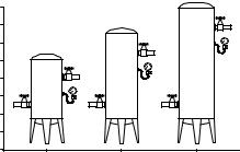
SYSTEM VOLUME
- |
+ |
Assorted Receiver Tanks
System volume defines how fast system pressure will rise or fall in reaction to either increased/decreased demand or increased/decreased supply. The larger the system volume, the slower the pressure changes in relation to increased/decreased demand or supply. Adequate system volume enables effective pressure control and avoids system over-pressurization in response to abrupt pressure fluctuations. Adequate system volume is created by correctly sizing and utilizing air receivers.
The most accurate way to determine the size of air receivers or the additional volume required would be to measure the size and duration of the largest demand event that occurs in the system, then size the volume large enough to ride through the event with an acceptable decrease in system pressure. Sizing the volume for the worst event will ensure system stability and effective control over all other normal operating conditions.
If measurement is not available, then estimating the largest event is a reasonable alternative. For example, assume that the largest demand event could be equal to the loss of the largest operating air compressor. System volume would be sized to allow time for a back-up compressor to be started and loaded with an acceptable decrease.
The following formula determines the recommended minimum storage volume for a compressed air system: V “volume required” = T “time of the event” (C “demand” x Pa “atmospheric pressure”)
Delta P “pressure drop” Example: T=15 Seconds (.25 minute), C=92 ft3, Pa = 14.5 PSI (1bar), Delta P = 5 PSI
4 - 25 hp compressors at 92 CFM (2.6 m3) each / 15 seconds to start and load a compressor. V = [.25 x (92 x 14.5)]/5
V = (.25 x 1334)/5 V = 333.5/5
V = 67
Gal = 67 x 7.48 Gal = 498.9
14
STANDARD SEQUENCE CONTROL STRATEGY
The standard configuration of the X4I provides FILO (First In/Last Out) sequence control strategy. The sequence control strategy consists of two components:
•The compressor rotation strategy
•The compressor load control strategy
 The rotation strategy defines how the compressors are arranged in a new sequence whenever a rotation event occurs. Rotation events are triggered by a periodic rotation based on a set interval, a set time of day each day, or a set time of day once a week.
 The compressor load control strategy defines when compressors load and unload based on system pressure variations and whether they run in fixed or variable speed modes.
Each compressor in a system will be assigned a permanent number based on where they are wired into the terminal PCB. Compressor 1 will always be wired into terminal X01; compressor 2 will always be wired into terminal X02, etc.
Each compressor will also be assigned a letter from A to D based on its location in the sequence:
•A = the base load compressor (the first compressor to be used).
•B = the first trim compressor (the second compressor to be used).
•C = the second trim compressor (the third compressor to be used).
•D = the third trim compressor (the last compressor to be used).
Compressor sequence assignments are reviewed and dynamically changed at a rotation event based on the sequencing strategy that is selected.
FIRST IN LAST OUT MODE (FILO)
The default configuration of the X4I provides FILO (First In/Last Out) sequence control strategy.
 The primary function of FILO (First In/Last Out) mode is to efficiently operate a compressed air system consisting of fixed speed compressors. The standard FILO rotation assignments can be modified using priority settings, which are explained later in this section.
Whenever a rotation event occurs, the sequence assignment for each compressor is rearranged. The compressor that was assigned as the base load compressor (A) is reassigned to third trim compressor (D) and all other compressors are incremented by one.
|
1 |
2 |
3 |
4 |
#1 |
A |
B |
C |
D |
#2 |
D |
A |
B |
C |
#3 |
C |
D |
A |
B |
#4 |
B |
C |
D |
A |
Sequence Rotation Table
SEQUENCE ROTATION EVENTS
 A sequence rotation event can be triggered in the following ways: a periodic interval, a pre-determined time each day, or a pre-determined time day and time each week.
Please refer to the Quick Setup Manual to determine how to configure the rotation events.
15
ADVANCED CONTROL FEATURES AND FUNCTIONS
ADVANCED SEQUENCE CONTROL STRATEGIES
The advanced configuration of the X4I provides VEC (Variable Energy Control) sequence control strategy, priority settings, table selection, and pre-fill operation.
VARIABLE ENERGY CONTROL MODE (VEC)


 The primary function of VEC mode is to accommodate a variable speed compressor connected to the X4I using an IRV-PCB interface.
VEC mode utilizes the FILO sequencing and rotation strategy with the additional control philosophy needed to efficiently control variable speed compressors.
In any set rotation sequence, the variable speed compressor that is assigned closest to A will be utilized in trim mode and will be allowed to throttle based on its local target pressure setpoint and the variations in system pressure. Any other variable speed compressors in the system will be held in fixed speed mode to prevent multiple variable speed compressors from oscillating.
The compressor that is allowed to run in variable speed mode will be evaluated at each rotation event.
Compressors are brought on or offline in response to changing demand using the FILO strategy. The base load compressor
(A) will be brought online first in the case of system pressure dropping below the low pressure setpoint. If pressure continues to drop, the first trim compressor (B) will also load. Compressors C and D will load in that order if needed. When system pressure rises above the high pressure setpoint, the last compressor to load will now be the first to be unloaded. Compressors C, B, and A will be unloaded, in that order, if system pressure continues to increase.
Compressor A will always be the first to be loaded and last to be unloaded.
PRIORITY SETTINGS
The sequence assignment pattern can be modified by using the priority settings.
Priority settings can be used to modify the rotation sequence assignments. Compressors can be assigned a priority of 1 to 4, where 1 is the highest priority. Any compressor can be assigned any priority and any number of compressors can share the same priority.
Priorities allow you to set up rotation groups. All compressors that have the same priority number will rotate inside their own group. The group with the highest priority will always be in the front of the sequence.
For example, in a four compressor system including one variable speed compressor in the compressor 1 position you may want the variable speed compressor to always be in the base load position. By assigning compressor 1 a priority of 1 and the other three compressors a priority of 2, the variable speed compressor will always remain at the front of the sequence:
|
1 |
2 |
3 |
4 |
|
1 |
2 |
2 |
2 |
#1 |
A |
B |
C |
D |
#2 |
A |
C |
D |
B |
#3 |
A |
D |
B |
C |
#4 |
A |
B |
C |
D |
Compressor 1 has priority 1, all other compressors have priority 2
In another example, there is a four compressor system that includes a compressor in the compressor 4 spot that is used only as an emergency backup compressor. To accomplish this, simply assign compressor 4 a lower priority than any other compressor in the system:
16
|
1 |
2 |
3 |
4 |
|
1 |
1 |
1 |
2 |
#1 |
A |
B |
C |
D |
#2 |
B |
C |
A |
D |
#3 |
C |
A |
B |
D |
#4 |
A |
B |
C |
D |
Compressor 4 has priority 2, all other compressors have priority 1
In a third example, there is a four compressor system that includes a variable speed compressor designated compressor 1 and a fixed speed compressor that is an emergency backup assigned as compressor 4. To ensure that compressor 1 is always at the front of the sequence and compressor 4 is always at the end of the sequence, set the priority as shown below:
|
1 |
2 |
3 |
4 |
|
1 |
2 |
2 |
3 |
#1 |
A |
B |
C |
D |
#2 |
A |
C |
B |
D |
#3 |
A |
B |
C |
D |
#4 |
A |
C |
B |
D |
Compressor 1 has priority 1, compressor 4 has priority 3 and all other compressors have priority 2
A last example involves another four compressor system that will be assigned into two independently rotation groups. Compressors 1 and 2 are given priority 1 and compressors 3 and 4 are given priority 2. This results in the rotation sequence shown below:
|
1 |
2 |
3 |
4 |
|
1 |
1 |
2 |
2 |
#1 |
A |
B |
C |
D |
#2 |
B |
A |
D |
C |
#3 |
A |
B |
C |
D |
#4 |
B |
A |
D |
C |
Two independently rotating compressor groups
T01
PH - - - -
PL - - - -
Pm - - - -
TABLES AND THE PRESSURE SCHEDULE SQ - - - -
The X4I operates based on settings that are configured into one of three tables. Each table defines the operational settings and sequence control mode of the X4I. The X4I can be instructed to change among the tables at any time based on the configuration of the pressure schedule.
This functionality allows the X4I to switch among multiple different system configurations without any disruption to control. This is particularly useful in the case of shift changes, or weekends when the system is to be deactivated.
Each table consists of the following parameters which can be set independently in each table:
•PH – High Pressure Setpoint
17
•PL – Low Pressure Setpoint
•Pm – Minimum pressure warning level
•SQ – Sequence Rotation Strategy
•01 – Compressor 1 Priority
•02 – Compressor 2 Priority
•03 – Compressor 3 Priority
•04 – Compressor 4 Priority
 The “maximum” pressure fault level and the rotation interval, or rotation time, are set independently in a configuration menu and are unchanging regardless of the table selected.
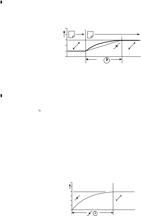
When the X4I is instructed to change between tables, it will not abruptly change the system operating parameters. The X4I will adjust the system target pressure upward or downward to the next table’s settings. This transition will occur gradually to preserve energy efficiency and safe, reliable control:
1 |
2 |
|
PC |
Changing Target Pressures
The time the system is allotted to change the target pressure is known as the Pressure Change Time (PC). This is a value that is adjustable in the system settings screen. See the Quick Setup Manual.
If the X4I is able to complete the transition in less time than is allotted without threatening energy efficiency then PC will be automatically shortened.
 An aggressively short time setting will compromise energy efficiency.
PRESSURE SCHEDULE 
The X4I is equipped with a real-time clock feature and pressure schedule functionality. The pressure schedule function can be used to provide system automation.
The pressure schedule consists of 28 individual settings that instruct the system to change from one table to another, or put the system into standby mode dependent on the time of day and the day of the week. The pressure schedule will cycle from 00:00 hours Monday (day #1) to 23:59 hours on Sunday (day #7) each calendar week.
The pressure schedule has the capability of changing tables based on the time of day, once each day, and once each day except weekends. Please see the Quick Setup Manual for detailed information on how to configure the pressure schedule.
PRE-FILL 
The pre-fill feature provides an energy efficient method of increasing pressure to normal operating levels upon system start. This feature avoids the inefficient potential for all compressors to start and load in an attempt to quickly get the system pressure up to normal levels:
System pressure during pre-fill
18
At system start (manual start or automated start from standby), the X4I will only load compressors that have been pre-set for pre-fill operation, for a pre-set period of time. The pre-fill time (PT) can be adjusted to suit system characteristics. The aim is to increase pressure to normal operational levels, using only the pre-determined compressors, prior to the pre-fill time expiring.
If normal operational pressure is reached prior to the set pre-fill time, the pre-fill function will automatically cease and normal operational control will begin. If normal operational pressure is not reached by the end of the pre-fill time, the X4I will utilize as many available compressors as required to achieve normal operational pressure as quickly as possible. Normal operational control will then begin.
Two pre-fill modes are available. Both function in the same way but differ in response to a failure, or loss, of a pre-fill compressor.
• |
Backup Mode: Compressor(s) can be pre-selected as “primary pre-fill” compressor(s) or “backup |
|
pre-fill” compressor(s). If a primary pre-fill compressor experiences a shutdown, or is stopped, it is |
|
replaced by a pre-defined backup compressor and pre-fill continues. |
•! X Standard Mode: If one or more of the pre-defined pre-fill compressors experiences a shutdown,
or is stopped, the pre-fill function is cancelled and normal operation begins.  To manually skip pre-fill mode, press and hold START for several seconds.
19

ALTERNATE CONTROL FEATURES AND FUNCTIONS
The alternate configuration of the X4I provides EHR (Equal Hours Run) and FIFO (First In/First Out) sequence control strategy.
EQUAL HOURS RUN MODE
 The primary function of EHR mode is to keep the running hours of all compressors in the system as close as possible. This provides the opportunity to service all of the compressors at the same time, given that the expected service interval for the compressors is similar.
 EHR is not an energy efficient focused mode of operation.
Each time a rotation event occurs, the compressor sequence is examined and will be rearranged based on the running hours recorded for each compressor. The compressor with the fewest running hours is assigned as the base load compressor and the compressor with the most running hours is assigned as the third trim compressor. For systems with more than two compressors, the compressors will be assigned from A to D in accordance with increasing running hours.
Example: The compressors in a four compressor system have the following recorded running hours when a rotation event occurs:
•Compressor 1 = 2200 hours
•Compressor 2 = 2150 hours
•Compressor 3 = 2020 hours
•Compressor 4 = 2180 hours
The new sequence order after the rotation event would be:
•Compressor 1 = D
•Compressor 2 = B
•Compressor 3 = A
•Compressor 4 = C
Compressor 3, which has the fewest running hours, will now be utilized more frequently in the new sequence, allowing running hours to accumulate at a faster rate.
The X4I continuously monitors the running status of each compressor and calculates the accumulated running hours. These readings are viewable and adjustable in the X4I C01 setting screens. The X4I will use these values during EHR mode. The running hours on the X4I should be routinely checked to see that they match the compressors’ local calculations, and adjusted if necessary.
 If a compressor is operated independently from the X4I, the running hours record may not be accurately updated.
 The running hours meter display on most compressors are intended for approximate service interval indication only and may deviate in accuracy over a period of time.
Compressors will be utilized following the FILO strategy.
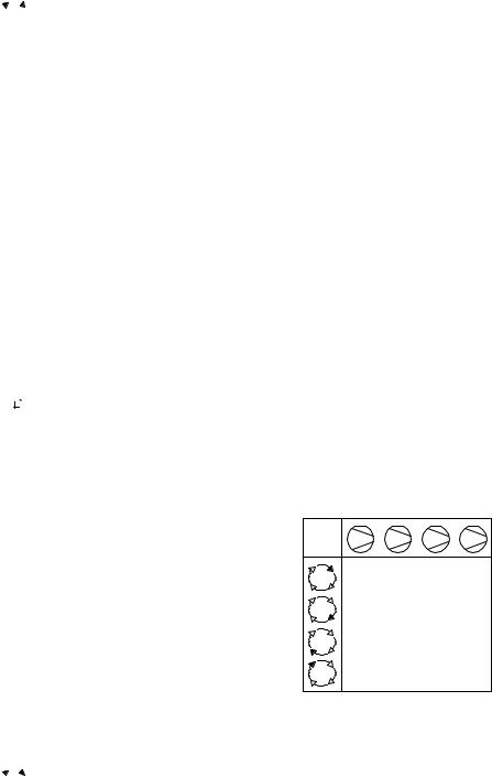
FIRST IN FIRST OUT MODE (FIFO)
 The primary function of FIFO mode is to keep a compressor loaded for the longest amount of time possible in order to minimize starts and stops on the motor. The compressors will continuously share pressure regulation.
 FIFO is not an energy efficient focused mode of operation.
FIFO does not follow sequence rotation events. Compressors are rotated each time a compressor is loaded. The rotation strategy becomes the control strategy using the control mode.
When system pressure drops below the low pressure setpoint, compressor 1 (A) will be the first to load as usual. If system pressure continues to decrease, compressor 2 (B) will be loaded and be reassigned to (A) while compressor 1 is reassigned
20
as (D). If this causes system pressure to rise above the high pressure setpoint, then compressor 1 (D) will be unloaded to allow compressor 2 (A) to maximize its run time. If system pressure decreases further, compressor 3 will be loaded and reassigned to (A) while Compressor 2 is reassigned to (D) and so on.
The most recently loaded compressor will always be assigned (A) and the longest running compressor will always be assigned (D).
1
2
3
4
ABCD DABC DABC CDAB BCDA BCDA BCDA ABCD
FIFO Rotation
21
SECTION 7 — INSTALLATION
It is recommended that installation and commissioning be carried out by an authorized and trained product supplier.
UNIT LOCATION
The X4I can be mounted on a wall using conventional bolts. The X4I can be located remotely from the compressors as long as it is within 330 feet (100 meters) of cable length. The X4I must also be located within 330 feet (100 meters) of the system pressure transducer.
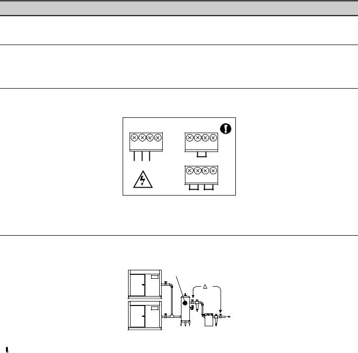
POWER SUPPLY
A fused switching isolator must be installed to the main incoming power supply, external to the X4I. The isolator must be fitted with a properly sized fuse to provide adequate protection to the power supply cable used (in accordance with local electrical and safety regulations).
XPM-TAC24
1 |
2 |
3 |
4 |
1 |
2 |
3 |
4 |
|
|
|
|
X04 |
|
|
|
L |
N |
E |
E |
VOLTAGE SELECT |
|||
|
|
|
X01 |
|
|
|
230Vac |
L N E |
|
1 |
2 |
3 |
4 |
||
|
X04 |
|
|
|
|||
|
|
|
|
|
|
|
|
VOLTAGE SELECT
115Vac
Power Supply Terminals
Ensure that the voltage select input is properly jumpered for the incoming power.
PRESSURE SENSOR LOCATION
The system pressure sensor (P) must be located where it will see the air pressure that is common to all of the compressors.
GENERATION SIDE PRESSURE CONTROL
|
P |
1 |
P |
|
|
2 |
|
Pressure Sensor Located Before Cleanup Equipment
 Demand side pressure will be lower than the system pressure due to pressure differential losses across air treatment equipment. The nominal system pressure will reduce as the air treatment differential pressure increases.
22
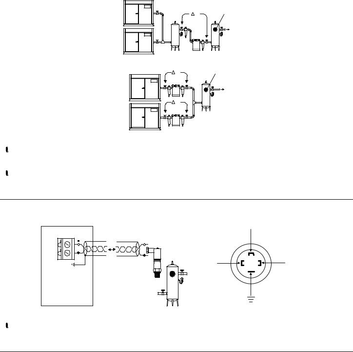
SYSTEM (DEMAND SIDE) PRESSURE CONTROL
1 |
P |
P |
|
|
2 |
Pressure Sensor Located After Shared Cleanup Equipment
P |
P |
1 |
|
P |
|
2 |
Pressure Sensor Located After Individual Cleanup Equipment
 Ensure each compressor is equipped with independent excess pressure shutdown. An increase in pressure differential across air treatment equipment can result in excess compressor discharge pressure.
 Regular routine monitoring of pressure differential across air treatment equipment is recommended.
PRESSURE SENSOR CONNECTION
The pressure sensor connects to terminal X05 of the X4I terminal PCB using a shielded 18 AWG maximum 2-conductor cable no more than 330 feet (100 meters) in length.
X05
26 |
|
- |
|
|
|
25 |
+ |
+ |
|
4-20mA
Pressure Sensor Wiring and Location
 Wire polarity is important.
IR-PCB INTERFACE MODULE
The IR-PCB is designed to interface a compressor with the X4I using a 7-conductor shielded cable no greater than 330 feet (100 meters) in length.
Each compressor in the system must be assigned a unique identification number from 1 up to the number of compressors in the system. The identification number should be clearly indicated on each compressor for operational reference.
For each compressor utilizing an IR-PCB, connection to the X4I the signal wires must be made to the correct X4I terminals for that compressor number. Compressor 1 should be wired to terminal X01 on the terminal PCB, Compressor 2 should be wired to terminal X02 on the terminal PCB, etc.
23
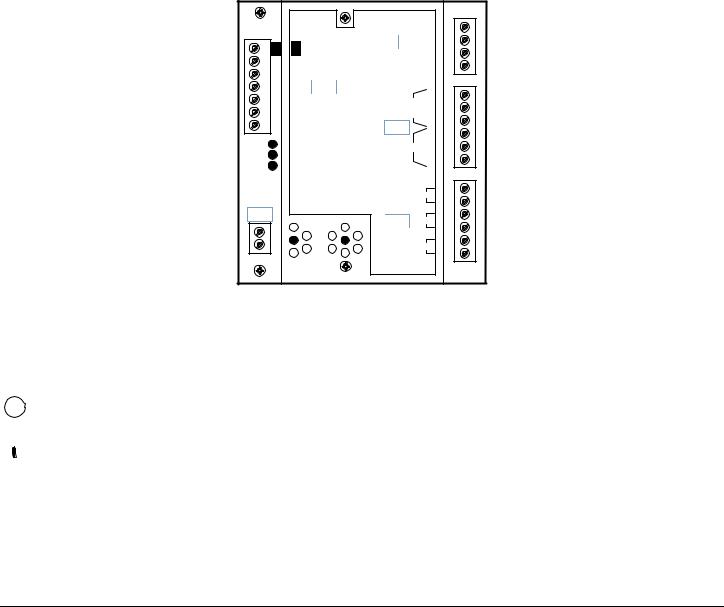
IR-PCB Interface Module
The IR-PCB is a DIN rail mountable module designed to be installed within the compressor starter enclosure.
Each air compressor must be equipped with a load/unload regulation system and, if not regulated with a single electromechanical pressure switch, have a facility for a remote load/unload control with the ability to accept a volt-free switching contact input for remote load/unload.
V For variable speed compressor(s) equipped with a “variable/fixed” digital input function, install a 7-conductor shielded cable from the IR-PCB to the X4I.
 Consult the air compressor manual or your air compressor supplier/specialist for details before installing the X4I.
Each air compressor must be equipped with an online/offline pressure regulation system capable of accepting a remote load/unload signal through a volt free switching contact or a single electro-mechanical pressure switch.
The IR-PCB accepts a 12V to 250V input voltage detection system and utilizes universal relay contact control outputs (250V “CE” / 115V “UL” @ 5A maximum) integrated directly into the circuits of an air compressor. The IR-PCB avoids the need for additional relays or remote inputs. The IR-PCB also acts as an electrical barrier between the compressor and the X4I providing protection and voltage isolation.
INPUT FUNCTIONS
The IR-PCB is fitted with a six-pin terminal, C04, for compressor monitoring. The IR-PCB uses two inputs, Ready and Run, to determine compressor status. An alarm input can be used if compressor warning indication is available and required. The alarm input is optional and is not necessary for system operation.
READY INPUT
The ‘Ready’ connection is intended to indicate that the compressor is in a “started” state, has no alarm condition that has shut down the compressor, and is ready to respond to X4I regulation without manual intervention.
24
 Loading...