


 Loading...
Operator’s manual
K 970 Ring 
Please read the operator’s manual carefully and make sure you understand the |
|
instructions before using the machine.It is the owner’s responsibility to make sure that |
English |
any persons who use this power cutter have read this manual! |
KEY TO SYMBOLS
Symbols on the machine
WARNING! The machine can be a dangerous tool if used incorrectly or carelessly, which can cause serious or fatal injury to the operator or others.
Please read the operator’s manual carefully and make sure you understand the instructions before using the machine.
Wear personal protective equipment. See instructions under the heading ”Personal protective equipment”.
WARNING! Dust forms when cutting, this can cause injuries if inhaled. Use an approved breathing mask. Avoid inhaling petrol fumes and exhaust fumes. Always provide for good ventilation.
WARNING! Kickbacks can be sudden, rapid and violent and can cause life threatening injuries. Read and understand the instructions in the manual before using the machine.
WARNING! Sparks may appear and start a fire when you work with the machine.
Choke
Air purge
Decompression valve
Refuelling, petrol/oil mix
2 – English
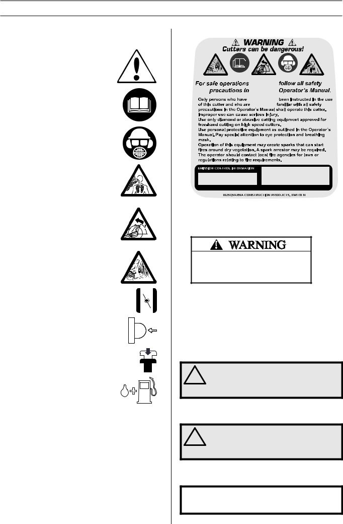
You will find the following labels on your power cutter:
The Emissions Compliance Period referred to on the Emission Compliance label indicates the number of operating hours for which the engine has been shown to meet Federal and Californian emissions requirements.
The engine exhaust from this product contains chemical known to the State of California to cause cancer, birth defects or other reproductive harm.
Other symbols/decals on the machine refer to special certification requirements for certain markets.
Explanation of warning levels
The warnings are graded in three levels.
WARNING!
WARNING! Used if there is a risk of serious
!injury or death for the operator or damage to the surroundings if the instructions in the manual are not followed.
CAUTION!
CAUTION! Used if there is a risk of injury to
!the operator or damage to the surroundings if the instructions in the manual are not followed.
NOTICE!
NOTICE! Used if there is a risk of damage to materials or the machine if the instructions in the manual are not followed.

CONTENTS
Contents |
|
KEY TO SYMBOLS |
|
Symbols on the machine ............................................. |
2 |
Explanation of warning levels ...................................... |
2 |
CONTENTS |
|
Contents ...................................................................... |
3 |
PRESENTATION |
|
Dear customer! ............................................................ |
4 |
Features ....................................................................... |
4 |
WHAT IS WHAT? |
|
What is what on the power cutter? ............................... |
5 |
MACHINE´S SAFETY EQUIPMENT |
|
General ........................................................................ |
6 |
BLADES |
|
General ........................................................................ |
8 |
Water cooling ............................................................... |
8 |
Diamond blades for different materials ........................ |
8 |
Sharpening diamond blades ........................................ |
8 |
Vibrations on diamond blades ...................................... |
8 |
Drive ............................................................................. |
8 |
Transport and storage .................................................. |
9 |
ASSEMBLING AND ADJUSTMENTS |
|
Fitting the blade ........................................................... |
10 |
Water hose ................................................................... |
11 |
FUEL HANDLING |
|
General ........................................................................ |
12 |
Fuel .............................................................................. |
12 |
Fueling ......................................................................... |
12 |
Transport and storage .................................................. |
12 |
OPERATING |
|
Protective equipment ................................................... |
14 |
General safety precautions .......................................... |
14 |
Transport and storage .................................................. |
17 |
STARTING AND STOPPING |
|
Before starting ............................................................. |
18 |
Starting ........................................................................ |
18 |
Stopping ....................................................................... |
19 |
MAINTENANCE |
|
General ........................................................................ |
20 |
Maintenance schedule ................................................. |
20 |
Cleaning ....................................................................... |
21 |
Functional inspection ................................................... |
21 |
Reconstructing the blade ............................................. |
26 |
TROUBLE SHOOTING |
|
Troubleshooting schedule ............................................ |
27 |
TECHNICAL DATA |
|
Technical data .............................................................. |
28 |
Cutting equipment ........................................................ |
28 |
FEDERAL EMISSION CONTROL WARRANTY |
|
STATEMENT |
|
YOUR WARRANTY RIGHTS AND OBLIGATIONS ..... |
29 |
English – 3

PRESENTATION
Dear customer!
Thank you for choosing a Husqvarna product!
It is our wish that you will be satisfied with your product and that it will be your companion for a long time. A purchase of one of our products gives you access to professional help with repairs and services. If the retailer who sells your machine is not one of our authorised dealers, ask him for the address of your nearest service workshop.
This operator’s manual is a valuable document. Make sure it is always at hand at the work place. By following its content (using, service, maintenance etc) the life span and the second-hand value of the machine can be extended. If you ever lend or sell this machine, make sure that the borrower or buyer gets the operator′s manual, so they will also know how to properly maintain and use it.
More than 300 years of innovation
Husqvarna AB is a Swedish company based on a tradition that dates back to 1689, when the Swedish King Charles XI ordered the construction of a factory for production of muskets. At that time, the foundation was already laid for the engineering skills behind the development of some of the world's leading products in areas such as hunting weapons, bicycles, motorcycles, domestic appliances, sewing machines and outdoor products.
Husqvarna is the global leader in outdoor power products for forestry, park maintenance and lawn and garden care, as well as cutting equipment and diamond tools for the construction and stone industries.
User responsibility
It is the owner’s/employer’s responsibility that the operator has sufficient knowledge about how to use the machine safely. Supervisors and operators must have read and understood the Operator’s Manual. They must be aware of:
•The machine’s safety instructions.
•The machine’s range of applications and limitations.
•How the machine is to be used and maintained.
National legislation could regulate the use of this machine. Find out what legislation is applicable in the place where you work before you start using the machine.
The manufacturer’s reservation
All information and all data in the Operator’s Manual were applicable at the time the Operator’s Manual was sent to print.
Husqvarna AB has a policy of continuous product development and therefore reserves the right to modify the design and appearance of products without prior notice.
For customer assistance, contact us at our website: www.usa.husqvarna.com
Features
Values such as high performance, reliability, innovative technology, advanced technical solutions and environmental considerations distinguish Husqvarna's products.
Some of the unique features of your product are described below.
4 – English
SmartCarb™
Built-in automatic filter compensation maintains high power and reduces fuel consumption.
Dura Starter™
Dust sealed starter unit, where the return spring and the pulley bearing are sealed which makes the starter virtually maintenance free and even more reliable.
X-Torq®
The X-Torq® engine provides a more accessible torque for a wider range of speeds which results in maximum cutting capacity. X-Torq® reduces the fuel consumption with up to 20% and the emissions with up to 60%.
EasyStart
The engine and starter are designed to ensure quick and easy starting of the machine. Reduces the pull resistance in the starter cord with up to 40%. (Reduces the compression during starting.)
Air purge
When you push the air purge diaphragm, fuel is pumped through to the carburettor. Fewer pulls are required for starting, meaning the machine becomes easier to start.
Efficient vibration damping system
Efficient vibration dampers spare arms and hands.
Large cutting depth
Gives a cutting depth of 260 mm (10”) which is double the depth compared to traditional blades. Cuts can be made efficiently from one side.

WHAT IS WHAT?
|
|
1 |
3 |
9 |
10 |
|
|
|
2 |
|
|
|
|
|
|
|
4 |
|
11 |
12 |
|
|
|
|
|
||
|
8 |
|
|
|
|
13 |
|
|
|
|
|
|
|
|
7 |
6 |
5 |
|
|
14 |
|
|
|
|
|
|
|
|
|
|
15 |
|
29 |
|
|
|
|
28 |
|
|
|
|
|
|
16 |
|
|
|
|
|
|
|
|
|
|
|
|
25 |
17 |
18 |
|
|
|
|
|
|
|
|
|
|
|
|
|
|
|
32 |
|
|
26 |
|
19 |
|
|
|
|
|
|
|
|
|
|
|
|
|
30 |
31 |
|
27 |
|
25 |
|
20 |
|
|
|
24 |
|
35 |
|
||
|
|
|
|
|
|
|
|
|
|
23 |
|
|
|
|
|
|
22 |
33 |
|
|
|
|
|
21 |
34 |
|
|
|
|
|
|
|
|
What is what on the power cutter?
1 |
Control for the guide rollers |
19 |
Choke |
2 |
Grease nipples |
20 |
Rear handle |
3 |
Blade guard/spray guard |
21 |
Stop switch |
4 |
Diamond blade |
22 |
Air purge |
5 |
Locking button for the drive wheel |
23 |
Cylinder cover |
6 |
Water connection with filter |
24 |
Locking nuts for the support roller arms |
7 |
Fuel cap |
25 |
Support rollers |
8 |
Type plate |
26 |
Drive wheel |
9 |
Adjuster screws |
27 |
Guide rollers |
10 |
Cover screws |
28 |
Tool bag |
11 |
Decompression valve |
29 |
Grease gun |
12 |
Starter handle |
30 |
6 mm hex key |
13 |
Throttle lockout |
31 |
Bearing grease |
14 |
Throttle trigger |
32 |
Water connector, GARDENA® |
15 |
Front handle |
33 |
Combination spanner, torx |
16 |
Water tap |
34 |
Open-ended spanner, 19 mm |
17 |
Warning decal |
35 |
Operator’s manual |
18 |
Air filter cover |
|
|
English – 5
MACHINE´S SAFETY EQUIPMENT
General
WARNING! Never use a machine that has
!faulty safety equipment! If your machine fails any of these checks contact your service agent to get it repaired.
The engine should be switched off, and the stop switch in STOP position.
This section describes the machine′s safety equipment, its purpose, and how checks and maintenance should be carried out to ensure that it operates correctly.
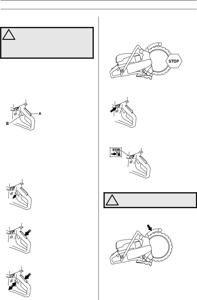
Throttle lockout
The throttle trigger lock is designed to prevent accidental operation of the throttle. When the lock (A) is pressed in this releases the throttle (B).
The trigger lock remains pressed in as long as the throttle is pressed. When the grip on the handle is released the throttle trigger and the throttle trigger lock both return to their original positions. This is controlled by two independent return spring systems. This means that the throttle trigger is automatically locked in the idle position.
Checking the throttle lockout
•Make sure the throttle control is locked at the idle setting when the throttle lockout is released.
•Press the throttle lockout and make sure it returns to its original position when you release it.
•Check that the throttle trigger and throttle lockout move freely and that the return springs work properly.
6 – English
•Start the power cutter and apply full throttle. Release the throttle control and check that the cutting blade stops and remains stationary. If the cutting blade rotates when the throttle is in the idle position you should check the carburettor’s idle adjustment. See instructions in the section "Maintenance".
Stop switch
Use the stop switch to switch off the engine.
Checking the stop switch
•Start the engine and make sure the engine stops when you move the stop switch to the stop setting.
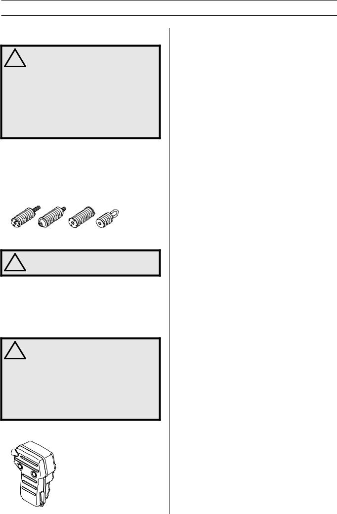
Blade guards
WARNING! Always check that the guard is
!correctly fitted before starting the machine.
This guard is fitted above the blade and is designed to prevent parts of the blade or cutting fragments from being thrown towards the user.
Check the blade guards
•Check that the guard over the blade is not cracked or damaged in any other way. Replace when damaged.
•Also check that the blade is fitted correctly and is not damaged in anyway. A damaged blade can cause personal injuries.
MACHINE´S SAFETY EQUIPMENT
Vibration damping system
WARNING! Overexposure to vibration can
!lead to circulatory damage or nerve damage in people who have impaired circulation. Contact your doctor if you experience symptoms of overexposure to vibration. Such symptoms include numbness, loss of feeling, tingling, pricking, pain, loss of strength, changes in skin colour or condition.These symptoms normally appear in the fingers, hands or wrists.These symptoms may be increased in cold temperatures.
•Your machine is equipped with a vibration damping system that is designed to reduce vibration and make operation easier.
•The machine′s vibration damping system reduces the transfer of vibration between the engine unit/cutting equipment and the machine′s handle unit. The engine body, including the cutting equipment, is insulated from the handles by vibration damping units.
Checking the vibration damping system
WARNING! The engine should be switched
!off, and the stop switch in STOP position.
•Check the vibration damping units regularly for cracks or deformation. Replace them if damaged.
•Check that the vibration damping element is securely attached between the engine unit and handle unit.
Muffler
WARNING! Never use a machine without a
!muffler, or with a faulty muffler. A damaged muffler may substantially increase the noise level and the fire hazard. Keep fire fighting equipment handy.
The muffler gets very hot during and after use.This also applies during idling. Be aware of the fire hazard, especially when working near flammable substances and/or vapours.
The muffler is designed to keep noise levels to a minimum and to direct exhaust fumes away from the user.
Inspecting the muffler
Check regularly that the muffler is complete and secured correctly.
English – 7
BLADES
General
WARNING! Cutting plastics with a diamond
!blade can cause kickback when the material melts due to the heat produced when cutting and sticks to the blade.
WARNING! Diamond blades get very hot
!when used. An overheated blade is a result of improper use, and may cause deformation of the blade, resulting in damage and injuries.
•Diamond blades consist of a steel core provided with segments that contain industrial diamonds.
Water cooling
WARNING! Cool diamond blades for wet
!cutting continuously with water to prevent overheating, which may deform the blade and cause damage to the blade and injury to the user.
•Water cooling must always be used.When wet cutting, the blade is continuously cooled to prevent overheating.
Diamond blades for different materials
•Diamond blades are ideal for masonry, reinforced concrete and other composite materials.
•We offers a number of blades for different materials in its range. Check with your Husqvarna dealer to see which blades are best suited for your usage.
Sharpening diamond blades
•Always use a sharp diamond blade.
•Diamond blades can become dull when the wrong feeding pressure is used or when cutting certain materials such as heavily reinforced concrete.Working with a blunt diamond blade causes overheating, which can result in the diamond segments coming loose.
•Sharpen the blade by cutting in a soft material such as sandstone or brick.
Vibrations on diamond blades
•The blade can become out of round and vibrate if a too high feed pressure is used.
•A lower feed pressure can stop the vibration. Otherwise replace the blade.
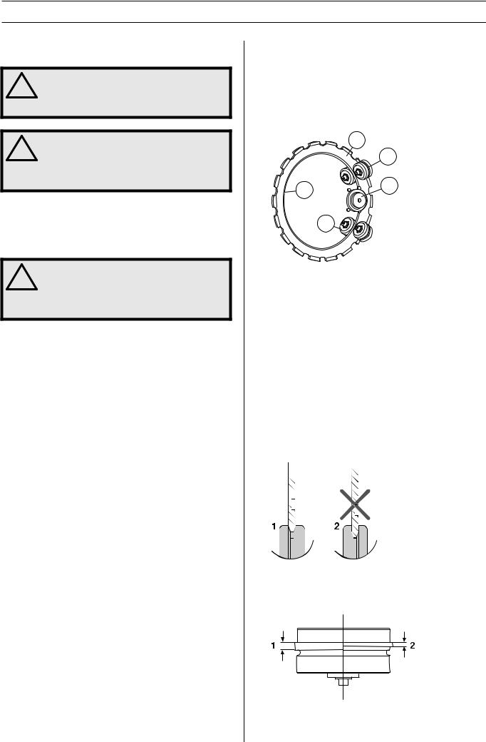
Drive
On account of the machine’s unique design the driving power is not transferred at the centre of the blade.
The flanges on the two guide rollers run in the blade’s groove. Springs on the guide rollers press out the rollers, which in turn press the V-shaped edge on the inside diameter of the blade against the V-shaped groove in the drive wheel. The drive wheel is fitted on an axle which is driven by the engine via a drive belt.
This allows a total cutting depth of 260 mm (10 inches) with a 350 mm (14 inches) diamond blade.
1 |
2 |
5 |
3 |
|
4 |
1Blade
2 Support rollers
3 Drive wheel
4 Guide rollers
5V-shaped edge
Checking wear
As the blade is used the inside diameter and the groove in the drive wheel become worn.
The ring cutter will also work well in the future if:
•the drive wheel is not too worn
1)New
2)Worn
•the guide rollers are not too worn
1)New, 3 mm (0.12’’)
2)Worn, ≤ 1,5 mm (0.06’’)
8 – English

BLADES
•adjustment between the rollers and blade is correct. See instructions in the section "Assembling and adjustments".
The roller setting should be checked twice during the life of the diamond blade, once after fitting the blade and when the blade is semi worn.
Transport and storage
•Store the blade in a dry place.
•Inspect new blades for transport or storage damage.
English – 9
ASSEMBLING AND ADJUSTMENTS
Fitting the blade
WARNING! It is forbidden to reconstruct a
!used blade. A used blade may be weakened. A reconstructed blade can crack or break into pieces and seriously injury the operator or other persons.
WARNING! Check that the blade is not
!damaged before fitting it on the machine. Damaged blades can disintegrate and cause serious personal injury.
NOTICE! Replace the drive wheel when fitting a new blade. A worn drive wheel can result in the blade slipping and becoming damaged.
Inadequate water flow drastically shortens the life of the drive wheel.
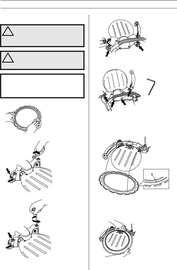
•Wipe off any dirt from the surface of the blade.
•Loosen the locking nuts on the support roller cover.
•Unscrew the adjuster screws a few turns.
•Loosen the knob to offload the springs.
•Remove the four screws holding the support roller guard using a 6 mm hex key and lift off the cover.
•Fit the blade.
•The blade has a groove (1) on one side that acts a the guide groove for the support rollers. Ensure that the V- shaped edge of the blade enters the drive wheel and that the blade’s guide groove fits in the guide rollers.
•Ensure that the V-shaped edge of the blade enters the drive wheel and that the blade’s guide groove fits in the guide rollers. See instructions in the section "Blades".
•Press in the guide roller if necessary, so that it climbs into the groove on the blade.
10 – English
Loading...