


 Loading...
HUV 5420 DXR Homologated
Diesel Vehicle for Europe
Owner’s Manual
[Refer to back cover for applicable build code range]

NOTICE
This manual is valid for vehicles manufactured in the build code range provided on the back cover of this manual. If the vehicle build code is different from that shown on the back cover of this manual, please contact your nearest dealer or go to www.husqvarna.com to retrieve the proper owner’s manual for the vehicle. See also Model Identification in this manual.
Your authorized representative checked the vehicle before it was delivered to you and will provide you a copy of the completed vehicle warranty registration form. No other warranties, express or implied, are contained herein.
Husqvarna is not liable for errors in this manual or for incidental or consequential damages that result from the use of the material in this manual.
This manual contains proprietary information that is protected by copyright. All rights are reserved. No part of this manual may be photocopied, reproduced, or translated to another language without the written consent of Husqvarna, Inc.
The information contained in this document is subject to change without notice.
Husqvarna reserves the right to make design changes to vehicles without obligation to make these changes on units previously sold.
If in English, this manual is the Original Instructions provided by the manufacturer. If in any language other than English, this manual is a translation of the Original Instructions.
Copyright © 2009 Husqvarna AB (publ). All rights reserved. Husqvarna and other product and feature marks are trademarks of Husqvarna Group.
HUV 5420 DXR Homologated Diesel Vehicle for Europe Owner’s Manual |
Page 1 |

FOREWORD
Thank you for choosing Husqvarna, the name most widely recognized as the industry leader in vehicle efficiency and long-lasting value. You have chosen the finest utility vehicle on the market. Please protect your investment and ensure that your Husqvarna vehicle(s) provides years of reliable, superior performance by reading and following the maintenance instructions in this manual.
Your comfort and safety are important to us, so we urge you to read and follow the step-by-step operating instructions and safety procedures in this manual. These instructions must be followed in order to avoid the risk of severe personal injury. If you rent or loan your vehicle to others, we recommend that you ask them to read this manual before they operate the vehicle.
Husqvarna products are backed by a customer support system designed to offer you fast, courteous service. In the event your Husqvarna vehicle needs repairs or service, please contact your local authorized Husqvarna dealer or distributor; he will be able to provide technical advice, perform warranty work, and sell parts and service manuals.
For the name and address of the authorized Husqvarna dealer or distributor nearest you, logon to our web site at www.husqvarna.com.
We hope you will consider this owner’s manual a permanent part of your Husqvarna vehicle. If you sell the vehicle, please include the manual so that the next owner will have the important operating, safety, and maintenance information it contains.
Page 2 HUV 5420 DXR Homologated Diesel Vehicle for Europe Owner’s Manual

TABLE OF CONTENTS |
|
Safety Decal and Feature Identification.................................................................................................................. |
4 |
Practice Safety..................................................................................................................................................... |
6 |
Safety Details....................................................................................................................................................... |
7 |
General Warnings................................................................................................................................................. |
8 |
General Information............................................................................................................................................. |
11 |
Model Identification.............................................................................................................................................. |
11 |
Controls and Indicators ....................................................................................................................................... |
12 |
Roll-Over Protective Structure and Seat Belts....................................................................................................... |
17 |
Pre-Operation and Daily Safety Checklist............................................................................................................. |
20 |
Driving Instructions............................................................................................................................................. |
21 |
Loading and Unloading Cargo ............................................................................................................................. |
24 |
Vehicle Load Capacities...................................................................................................................................... |
24 |
Towing with the Vehicle....................................................................................................................................... |
26 |
Transporting on a Trailer ..................................................................................................................................... |
26 |
Storage.............................................................................................................................................................. |
27 |
Maintenance ...................................................................................................................................................... |
28 |
Periodic Service Schedule................................................................................................................................... |
29 |
Periodic Lubrication Schedule ............................................................................................................................. |
32 |
Brake Fluid Reservoir ......................................................................................................................................... |
33 |
Engine Oil.......................................................................................................................................................... |
33 |
Gearcase Lubrication.......................................................................................................................................... |
38 |
Engine Coolant................................................................................................................................................... |
39 |
Air Intake System ............................................................................................................................................... |
40 |
Fueling Instructions............................................................................................................................................. |
41 |
Battery............................................................................................................................................................... |
43 |
Using A Booster Battery (Jump Starting) .............................................................................................................. |
45 |
Cleaning the Vehicle........................................................................................................................................... |
46 |
Accessories........................................................................................................................................................ |
47 |
Vehicle Specifications ......................................................................................................................................... |
48 |
HUV 5420 DXR Homologated Diesel Vehicle for Europe Owner’s Manual |
Page 3 |
Safety Decal and Feature Identification
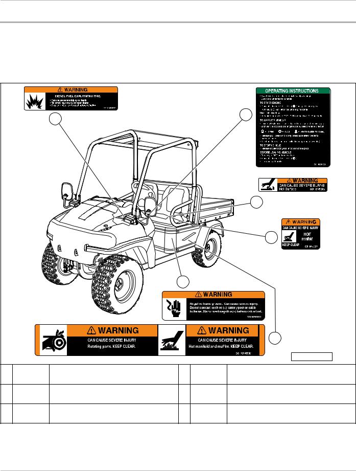
SAFETY DECAL AND FEATURE IDENTIFICATION
The following pages contain safety decal and feature identification information. For detailed information on specific features, read the appropriate section in this manual.
HUSQVARNA HUV 5420 DXR HOMOLOGATED DIESEL VEHICLE
6
4
1 |


 2
2
3
|
|
|
|
5 |
|
|
|
|
377 |
1 |
Decal, Hot Surface Warning (on coolant pipes and |
4 |
102459201 |
Decal, Diesel Fuel Warning (on frame, near fuel |
102458901 |
tank) |
|||
|
underside of seats) (on bed seal) |
|
|
|
2 |
Decal, Hot Manifold Warning (on engine, near |
5 |
102459501 |
Decal, Rotating/Hot Parts Warning (on frame near |
102459001 |
battery) |
|||
|
manifold) |
|
|
|
3 |
Decal, Ground Warning (on vehicle frame, near |
6 |
102884301 |
Decal, Operating Instructions (on instrument panel) |
102459101 |
||||
|
battery) |
|
|
|
Page 4 HUV 5420 DXR Homologated Diesel Vehicle for Europe Owner’s Manual

Safety Decal and Feature Identification
HUSQVARNA HUV 5420 DXR HOMOLOGATED DIESEL VEHICLE
! WARNING
5 |
8 |
|
7
3
6
1
2 |
9 |
4 |
|
|
|
|
|
|
|
|
10 |
|
|
|
|
|
|
|
|
|
|
|
|
||
|
|
|
|
|
|
|
|
378 |
|
|
|
|
|
|
|
|
|
|
|
|
|
|
|
|
|
|
|
|
||||
1 |
1011553 |
Decal, Trailer Hitch Tongue Weight Notice (on |
6 |
102460201 |
Decal, Rotating Parts Warning (on vehicle body, |
|||||
trailer/receiver hitch) |
under seat) |
|||||||||
|
|
|
|
|
||||||
|
|
|
|
|
|
|
|
|
|
|
2 |
101609401 |
Decal, Crush Area Warning (behind seat, near |
7 |
102884401 |
Decal, Rollover Warning (on instrument panel) |
|||||
cargo bed) |
||||||||||
|
|
|
|
|
|
|
|
|
||
|
|
|
|
|
|
|||||
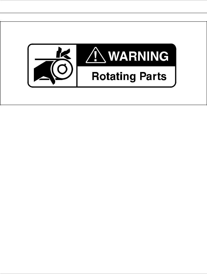
3 |
102224001 |
Decal, Rotating Parts Warning (on frame) |
8 |
102961201 |
Decal, ROPS Warning (on ROPS) |
|||||
|
|
|
|
|
|
|
|
|
|
|
4 |
102459301 |
Decal, Bed Latch Warning (on vehicle body, below |
9 |
103332501 |
Decal, Vehicle Loading Instructions (on cargo bed) |
|||||
bed latch) |
||||||||||
|
|
|
|
|
|
|
|
|
||
|
|
|
|
|
|
|||||
5 |
102459401 |
Decal, Young Driver Warning (on ROPS) |
10 |
103332601 |
Decal, Vehicle Loading Instructions (on cargo bed) |
|||||
|
|
|
|
|
|
|
|
|
|
|
HUV 5420 DXR Homologated Diesel Vehicle for Europe Owner’s Manual |
Page 5 |
Practice Safety
PRACTICE SAFETY
399
Figure 1 Practice Safety
Safety signs like you see above may at first seem shocking, but their impact is mild compared with the reality of severe personal injury.
Your safety and satisfaction are of the utmost importance to us. That is why before operating the vehicle, we urge you to review the information in this manual. Understand and become familiar with the DANGER, WARNING, and CAUTION statements and procedures it contains, along with the safety decals that are affixed to your vehicle.
Take time to understand the language of safety. It is a language that can save your life.
Page 6 HUV 5420 DXR Homologated Diesel Vehicle for Europe Owner’s Manual

Safety Details
SAFETY DETAILS
 WARNING
•This owner’s manual should be read completely before attempting to drive or service the vehicle. Failure to follow the instructions in this manual could result in property damage, severe personal injury, or death.
•The homologated diesel vehicle is equipped to operate at a top speed of 25 mph (40 km/h) and is intended for use as a low-speed vehicle.
 WARNING
WHEN OPERATING VEHICLE ON PUBLIC ROADS
•THIS VEHICLE OFFERS MUCH LESS CRASH PROTECTION THAN A REGULAR CAR, VAN, OR TRUCK. THIS MEANS A HIGHER RISK OF INJURY OR DEATH IN COLLISIONS, EVEN AT LOW SPEEDS.
•The higher the speed of the traffic around you, the higher the risk of injury.
•To reduce these risks:
–Avoid roads with regular traffic, even if the speed limit is low.
–Whenever possible, stay on roads and lanes limited to low-speed vehicles.
–Wear your seat belts at all times.
–Avoid operating vehicle at night, because your vehicle may be difficult for others to see.
–Never drink and drive.
–To help avoid rollovers, SLOW DOWN BEFORE MAKING SHARP TURNS.
It is important to note that some vital statements throughout this manual and on the decals affixed to the vehicle are preceded by the words DANGER, WARNING, or CAUTION. For your protection, we recommend that you take special notice of these safety precautions. Safety precautions are essential and must be followed.
If any of the operation or warning decals on the vehicle become damaged, have been removed, or cannot be easily read, they should be replaced immediately to avoid possible property damage, personal injury, or death. Contact your dealer.
 DANGER
• A DANGER indicates an immediate hazard that will result in severe personal injury or death.
 WARNING
• A WARNING indicates an immediate hazard that could result in severe personal injury or death.
 CAUTION
•A CAUTION with the safety alert symbol indicates a hazard or unsafe practice that could result in minor personal injury.
HUV 5420 DXR Homologated Diesel Vehicle for Europe Owner’s Manual |
Page 7 |

General Warnings
CAUTION
•A CAUTION without the safety alert symbol indicates a potentially hazardous situation that could result in property damage.
GENERAL WARNINGS
The following safety statements must be heeded whenever the vehicle is being operated, repaired, or serviced.
See Safety Decal and Feature Identification on page 4. Other specific safety statements appear throughout this manual and on the vehicle.
 DANGER
•Battery – Explosive gases! Do not smoke. Keep sparks and flames away from the vehicle and service area. Ventilate when charging or operating vehicle in an enclosed area. Wear a full face shield and rubber gloves when working on or near batteries.
•Diesel – Flammable! Explosive! Do not smoke. Keep sparks and flames away from the vehicle and service area. Service only in a well-ventilated area.
•Do not operate engine in an enclosed area without proper ventilation. The engine produces carbon monoxide, which is an odorless, deadly poison.
•The vehicle will not provide protection from lightning, flying objects, or other storm-related hazards. If caught in a storm while driving a Husqvarna vehicle, exit the vehicle and seek shelter in accordance with applicable safety guidelines for your location.
 WARNING
•Follow the procedures exactly as stated in this manual, and heed all DANGER, WARNING, and CAUTION statements in this manual as well as those on the vehicle.
•Do not leave children unattended on vehicle.
•Children requiring a child safety seat must not ride on the vehicle. Comply with state and local laws pertaining to child safety.
•The driver and passenger must be restrained at all times with the seat belts provided to help prevent injury in the event of sudden braking, collision, or roll-over.
•No more than one person per bucket seat at one time. No more than two persons per bench seat at one time. Do not allow people to ride in any part of the vehicle that is not equipped with a seat and a seat belt. Do not allow a passenger to hold a child in his or her lap while the vehicle is moving.
•Prior to leaving the vehicle unattended or servicing the vehicle set the park brake, place the Forward/Reverse handle in the NEUTRAL position, turn the key switch to the OFF position, and remove the key. Chock the wheels when servicing the vehicle.
•Improper use of the vehicle or failure to properly maintain it could result in decreased vehicle performance, severe personal injury, or death.
•Any modification or change to the vehicle that affects the stability or handling of the vehicle, or increases maximum vehicle speed beyond factory specifications, could result in severe personal injury or death.
•Check the vehicle for proper location of all vehicle safety and operation decals and make sure they are in place and are easy to read.
•For vehicles with cargo beds, remove all cargo before raising the bed or servicing the vehicle. If the vehicle is equipped with a prop rod, ensure that it is securely engaged while bed is raised. Do not close bed until all persons are clear of cargo bed area. Keep hands clear of all crush areas. Do not
WARNING CONTINUED ON NEXT PAGE
Page 8 HUV 5420 DXR Homologated Diesel Vehicle for Europe Owner’s Manual
General Warnings
 WARNING
drop cargo bed; lower gently and keep entire body clear. Failure to heed this warning could result in severe personal injury or death.
•Only trained technicians should service or repair the vehicle. Anyone doing even simple repairs or service should have knowledge and experience in electrical and mechanical repair. The appropriate instructions must be used when performing maintenance, service, or accessory installation.
•To avoid unintentionally starting the vehicle, disconnect battery. See Disconnecting the Battery – Diesel Vehicles on page 9.
•Frame ground – Do not allow tools or other metal objects to contact frame when disconnecting battery cables or other electrical wiring. Do not allow a positive wire to touch the vehicle frame, engine, or any other metal component.
•Wear safety glasses or approved eye protection when servicing the vehicle. Wear a full face shield and rubber gloves when working on or near batteries.
•Do not wear loose clothing or jewelry such as rings, watches, chains, etc., when servicing the vehicle.
•Use insulated tools when working near batteries or electrical connections. Use extreme caution to avoid shorting of components or wiring.
•When servicing the vehicle with part of the vehicle on jack stands, do not operate the engine with the Forward/Reverse handle in either the FORWARD or REVERSE position. The all-wheel drive system will engage any wheel(s), front or rear, with traction.
DISABLING THE VEHICLE
1.Set the park brake.
2.Turn the key switch OFF and remove the key.
3.Place the Forward/Reverse control in the NEUTRAL position.
4.In addition, chock the wheels if servicing or repairing the vehicle.
DISCONNECTING THE BATTERY – DIESEL VEHICLES
1.Disable the vehicle. See Disabling the Vehicle on page 9.
2.Disconnect the battery cables, negative (–) cable first, as shown (Figure 2).
CONNECTING THE BATTERY – DIESEL VEHICLES
1.Connect the battery cables, positive (+) cable first.
2.Tighten battery terminals to 80 in-lb (9 N·m).
3.Coat terminals with Battery Terminal Protector Spray (P/N 603 00 00-03) to minimize corrosion.
HUV 5420 DXR Homologated Diesel Vehicle for Europe Owner’s Manual |
Page 9 |

General Warnings
1.Remove negative battery cable.
2.Remove positive battery cable. Connect battery cables in reverse order.
188 |
189 |
Figure 2 Battery Cable Removal |
Figure 3 All-Wheel Drive Warning |
RECYCLING LEAD-ACID BATTERIES
 WARNING
•Lead-acid batteries contain lead (Pb), other metals, acids and other compounds. If improperly handled, they can contaminate both water and soil, causing environmental damage and personal injury.
Lead-acid batteries are identified by the symbol shown below and should be properly recycled (Figure 4). They cannot be disposed as municipal waste and must be collected separately. Responsibility for environmental protection must be shared, not only by the manufacturers of the batteries, but by people who use the batteries as well. Please contact your nearest Husqvarna dealer or distributor for information on how to properly recycle your batteries.
1403
Figure 4 Dispose of Lead-acid Batteries Properly
Page 10 HUV 5420 DXR Homologated Diesel Vehicle for Europe Owner’s Manual
General Information
GENERAL INFORMATION
This homologated vehicle is designed for operation on public roads. Its construction also allows operation on rough terrain with inclines not exceeding 20%.
This manual includes operating procedures, maintenance, and regular servicing information for the Husqvarna HUV 5420 DXR vehicles that have been homologated for Europe.
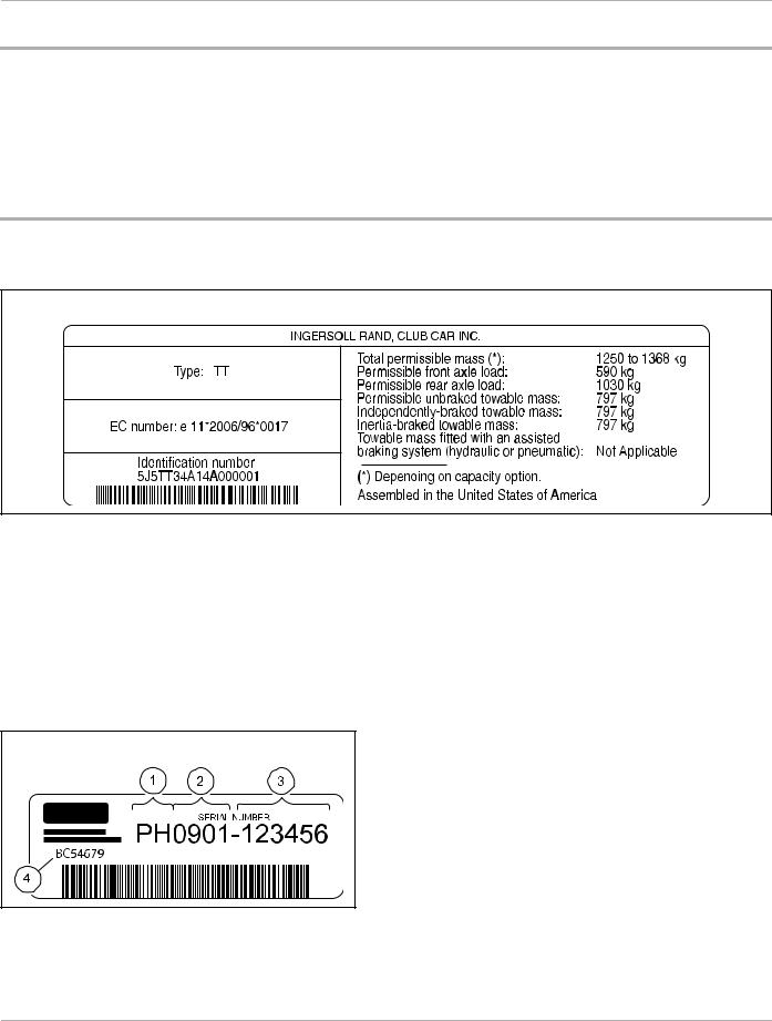
MODEL IDENTIFICATION
The vehicle identification number (Figure 5) is located on the center cross bar underneath the bed at the rear of the car. See following NOTE.
1437 |
Figure 5 Vehicle Identification Number Decal
NOTE: Have the vehicle identification number available when ordering parts or making inquiries.
Build Code: The build code (4) is a five-digit number that appears on the vehicle serial number decal (Figure 6). The build code exists to enable the user to identify the correct owner’s manual for a vehicle. This owner’s manual is valid for the build code range indicated on the back cover of this owner’s manual.
1400 |
Figure 6 Serial Number Decal with the Vehicle Build Code
HUV 5420 DXR Homologated Diesel Vehicle for Europe Owner’s Manual |
Page 11 |
Controls and Indicators
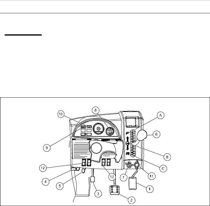
CONTROLS AND INDICATORS
See General Warnings on page 8.
 WARNING
•Before allowing anyone to drive the vehicle, make sure the driver is familiar with all controls and operating procedures.
•Do not tamper with the high idle speed setting on the diesel vehicle. Doing so will void the warranty, as well as damage the engine and other components, and could result in property damage, personal injury, or death due to unsafe speeds.
•Do not shift the Forward/Reverse handle while the vehicle is in motion.
•Engine must be at idle before shifting the Forward/Reverse handle. Failure to do so may result in injury to inattentive passengers and (or) damage to the vehicle.
•To avoid unintentionally starting or rolling the vehicle, place attachment on the ground, set the park brake, place the Forward/Reverse handle in the NEUTRAL position, turn the key switch to the OFF position, and remove the key when leaving the vehicle.
229
Figure 7 Instrument Panel
1. |
Accelerator Pedal |
6. |
Forward/Reverse Handle |
11. 12-volt Accessory Outlet |
|
|
|
|
|
|
|
2. |
Brake Pedal |
7. |
Key Switch |
12. |
Headlight/Taillight Control |
|
|
|
|
|
|
3. |
Park Brake Pedal |
8. |
Fuel Gauge Meeting |
13. |
Electric Bed Lift Switch |
|
|
|
|
|
|
4. |
Park Brake Release Handle |
9. |
Low Oil Warning Light |
14. |
Turn Signal Indicator Lights |
|
|
|
|
|
|
5. |
Steering Adjustment Lock Lever |
10. High-Temperature Warning Light |
|
|
|
|
|
|
|
|
|
|
|
|
|
|
|
Page 12 HUV 5420 DXR Homologated Diesel Vehicle for Europe Owner’s Manual

Controls and Indicators
 WARNING
• Moving parts! Keep clear of the engine compartment while the engine is running.
CAUTION
•Do not shift the Forward/Reverse handle while the accelerator pedal is pressed. Shift the handle only when the vehicle is at a complete stop and the engine is at idle. Failure to heed this caution could result in damage to the transmission.
NOTE: The key can be removed only when the key switch is in the OFF position.
KEY SWITCH
The key switch (7) is mounted on the instrument panel to the right of the steering column (Figure 7). It has four positions: PREHEAT, OFF, ON, and START.
Use the PREHEAT feature if the temperature falls below –5 °C (23 °F). Do not hold the key in the PREHEAT position longer than 20 seconds. To preheat the glow plugs in cold weather, turn the key to the PREHEAT position, and hold it there for 10-15 seconds. Then turn the key to the START position, and hold it there until the engine starts. If the engine does not start after 10-15 seconds, turn the key to the OFF position and repeat the procedure. Once the engine starts, release the key and it will return to the ON position. The engine will idle in neutral. The engine will continue to idle until the key is turned to the OFF position. See previous WARNING, CAUTION, and NOTE.
FORWARD/REVERSE CONTROL
The Forward/Reverse handle (6) is located on the right side of the instrument panel (Figure 7). The handle has three distinct positions: FORWARD (A), NEUTRAL (B), and REVERSE (C). Push the handle up to operate the vehicle in the forward direction, or pull the handle down to operate the vehicle in reverse. The engine can be started only when the handle is in the NEUTRAL (middle) position. The engine must be at idle before shifting the Forward/Reverse handle.
See preceding WARNING and CAUTION.
Husqvarna vehicles operate at a reduced speed in reverse. The reverse buzzer will sound as a warning when the Forward/Reverse handle is in the REVERSE position.
ACCELERATOR PEDAL
The accelerator pedal (1) is the pedal farthest to the right (Figure 7).
With the engine running and the Forward/Reverse handle in the FORWARD or REVERSE position, vehicle speed will increase as the accelerator pedal is pressed. When the accelerator pedal is released, it will return to the original position and the engine will idle. See preceding WARNING and CAUTION.
BRAKE PEDAL
The brake pedal (2) is located to the immediate left of the accelerator pedal (Figure 7). To slow or stop the vehicle, press the brake pedal.
HUV 5420 DXR Homologated Diesel Vehicle for Europe Owner’s Manual |
Page 13 |
Controls and Indicators
BRAKE LIGHTS
The brake lights illuminate when the brake pedal is pressed. When the park brake is engaged, the brake lights will turn off. See following NOTE.
NOTE: When the key switch is in the OFF position, the brake lights are disabled.
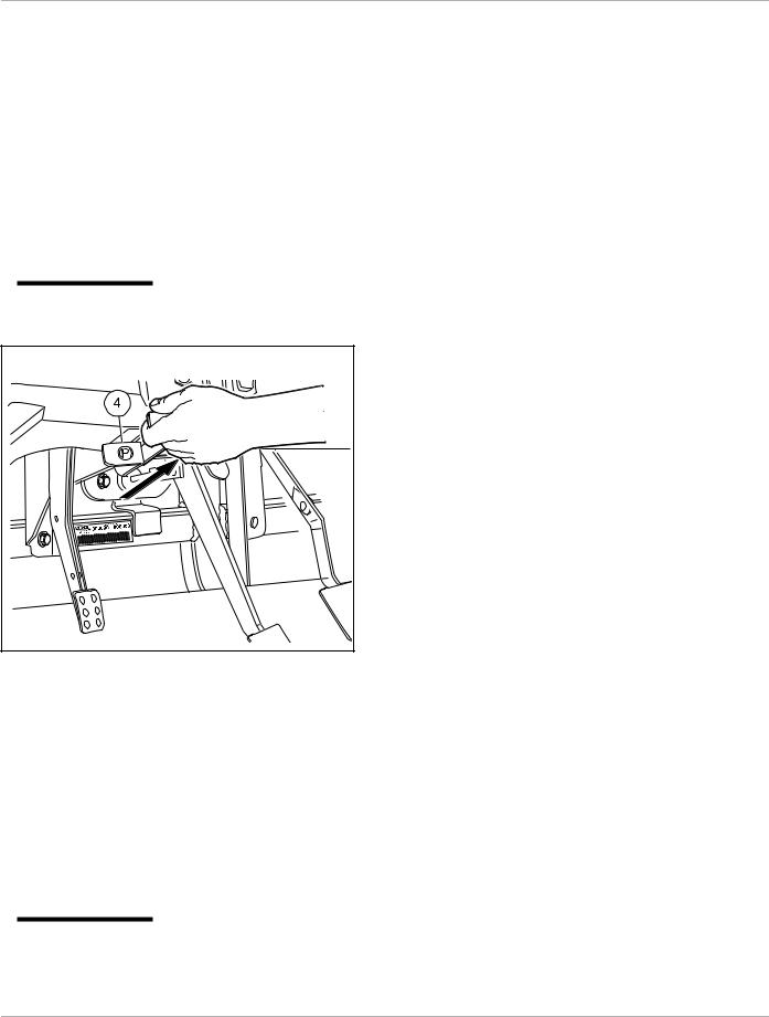
PARK BRAKE
The park brake pedal (3) is located to the left of the brake pedal (Figure 7). To engage the park brake, first apply pressure to the brake pedal, then firmly press the park brake pedal until it latches into place. To disengage the park brake, pull the park brake release handle (4) (Figure 8). See following WARNING.
 WARNING
• The park brake has multiple locking positions and should be firmly locked to prevent the vehicle from rolling.
191
Figure 8 Park Brake Release
STEERING ADJUSTMENT LOCK
The steering wheel position is adjustable. To adjust the steering wheel position, press down on the steering adjustment lock lever (5), then move the steering wheel to the desired position (Figure 7). While holding the steering wheel in the desired position, pull up on the steering adjustment lock lever to firmly lock the steering column in position.
See following WARNING.
 WARNING
• Ensure that the steering wheel lock is fully engaged before operating the vehicle.
Page 14 HUV 5420 DXR Homologated Diesel Vehicle for Europe Owner’s Manual

Controls and Indicators
12-VOLT ACCESSORY OUTLET
The 12-volt accessory outlet (11) is located to the right of the key switch (Figure 7). It provides a constant 12VDC with the key switch in the ON or OFF position. See following NOTE.
NOTE: Extended use of this accessory outlet can cause the battery to become heavily discharged.
LOW OIL WARNING LIGHT
The low oil warning light (9) is located on the instrument panel just to the left of the steering column (Figure 7). If the warning light lights up, oil should be checked and added to the engine as necessary before vehicle use continues. The vehicle should never be driven when the low oil warning light remains lit. If the warning light alternately lights and darkens, the vehicle may be driven, but oil should be added at the first opportunity. If the oil level is correct and the warning light remains lit, have a trained technician check the vehicle. See following CAUTION.
CAUTION
•Failure to add oil immediately when the low oil warning light stays on may result in permanent engine damage.
FUEL GAUGE/HOUR METER
The fuel gauge and hour meter (8) are housed together on the right side of the instrument panel (Figure 7). The fuel gauge operates when the key switch is in the ON position and allows the operator to monitor the fuel level in the vehicle. The hour meter operates only when the engine is running, and should be used by the trained technician to track vehicle usage and determine when periodic service procedures are required. See Periodic Service Schedule on page 29.
HEADLIGHT/TAILLIGHT CONTROL
The headlight/taillight control (12) is located on the left side of the instrument panel (Figure 7). Press the headlight rocker switch to turn the headlights on or off. See following NOTE.
NOTE: Using the headlights for extended periods while the engine is either off or idling will discharge the battery.
TURN SIGNAL
There are two turn signal indicator lights (14) on the instrument panel (Figure 7). The upper symbol indicates the turn direction for the vehicle; the lower symbol indicates the turn direction for an attached trailer.
The turn signal control (1) is mounted on the steering column (Figure 9). Move the handle up to indicate a right-hand turn. Move the handle down to indicate a left-hand turn. Return the handle to the center position after completing a turn.
NOTE: If the turn signal light burns out, the indicator light on the instrument panel will flash at twice the normal speed.
If an attached trailer’s turn signal light burns out, the indicator light will not flash.
HORN
The horn button (3) is located on the end of the turn signal handle (Figure 9). Press the button in to sound the horn.
HUV 5420 DXR Homologated Diesel Vehicle for Europe Owner’s Manual |
Page 15 |
Loading...