


J-handle 24
Table of contents
 Loading...
EE
EE
nn
nn
gg
gg
ll
ll
ii
ii
ss
ss
hh
hh
((
((
22
22
--
--
99
99
))
))
FF
FF
rr
rr
ee
ee
nn
nn
cc
cc
hh
hh
((
((
11
11
00
00
--
--
11
11
77
77
))
))
SS
SS
pp
pp
aa
aa
nn
nn
ii
ii
ss
ss
hh
hh
((
((
11
11
88
88
--
--
22
22
55
55
))
))
J-handle 24 mm,
grasblade
Oper
ator’s manual Manuel d’utilisation
Manual de instrucciones
Please r
ead the operator’s manual carefully and make sure you understand the instructions before using the machine.
Lire attentivement et bien assimiler le manuel d’utilisation avant d’utiliser la machine.
Lea detenidamente el manual de instrucciones y asegúrese de entender su contenido antes de utilizar la máquina.
CONTENTS
2
–
English
Contents
Note the f
ollowing before
starting:
Please read the oper
ator’s manual carefully and make
sure you understand the instructions before using the
machine. These instructions supplement the instructions
that were included with the machine. For other
procedures, please refer to the operating instructions for
the machine.
Husqvarna AB has a policy of continuous product
development and therefore reserves the right to modify
the design and appearance of products without prior
notice.
Long-term exposure to noise can result in permanent
hearing impairment. So always use approved hearing
protection.
IMPORTANT! The trimmer guard must be replaced with
the accompanying combination guard if a grass blade is
fitted to the machine.
For customer assistance, contact us at our website:
www.husqvarna.com
CONTENTS
Contents
............................................................... 2
Note the following before starting: ........................ 2
WHA
T IS WHAT?
What is what?
....................................................... 3
SAFETY INSTR
UCTIONS
Cutting equipment
................................................. 4
Sharpening grass knifes and grass blades ........... 4
General working instructions ................................ 4
ASSEMBL
Y
Fitting the J-handle
.............................................. 6
Fitting the suspension ring .................................... 6
Assembling the cutting equipment ........................ 6
Fitting the blade guard/combination guard, grass
blade and grass cutter ..........................................
7
ST
ARTING AND STOPPING
Chec
k before starting ............................................ 8
TECHNICAL D
ATA
T
echnical data ....................................................... 9
!
W
ARNING! Under no circumstances may
the design of the machine be modified
without the permission of the
manufacturer. Always use genuine
accessories. Non-authorized
modifications and/or accessories can
result in serious personal injury or the
death of the operator or others.
Your warranty may not cover damage or
liability caused by the use of non-
authorized accessories or replacement
parts.
!
W
ARNING! This accessory may only be
used together with the intended trimmer,
see under heading ”Approved
accessories” in chapter Technical data in
the machine’s Operator’s Manual.
!
W
ARNING! Only grass blades/grass
cutters or trimmer heads/plastic blades
may be used when the J-handle is fitted.
Saw blades must never be used with the
J-handle.
IMPOR
TANT! Never use a cutting attachment without
an approved guard. See the chapter on Technical data.
If an incorrect or faulty guard is fitted this can cause
serious personal injury.
IMPORTANT! Wear boots with steel toe-caps and non-
slip sole if a grass blade is fitted to the machine.
English
–
3
WHA
T IS
WHA
T?
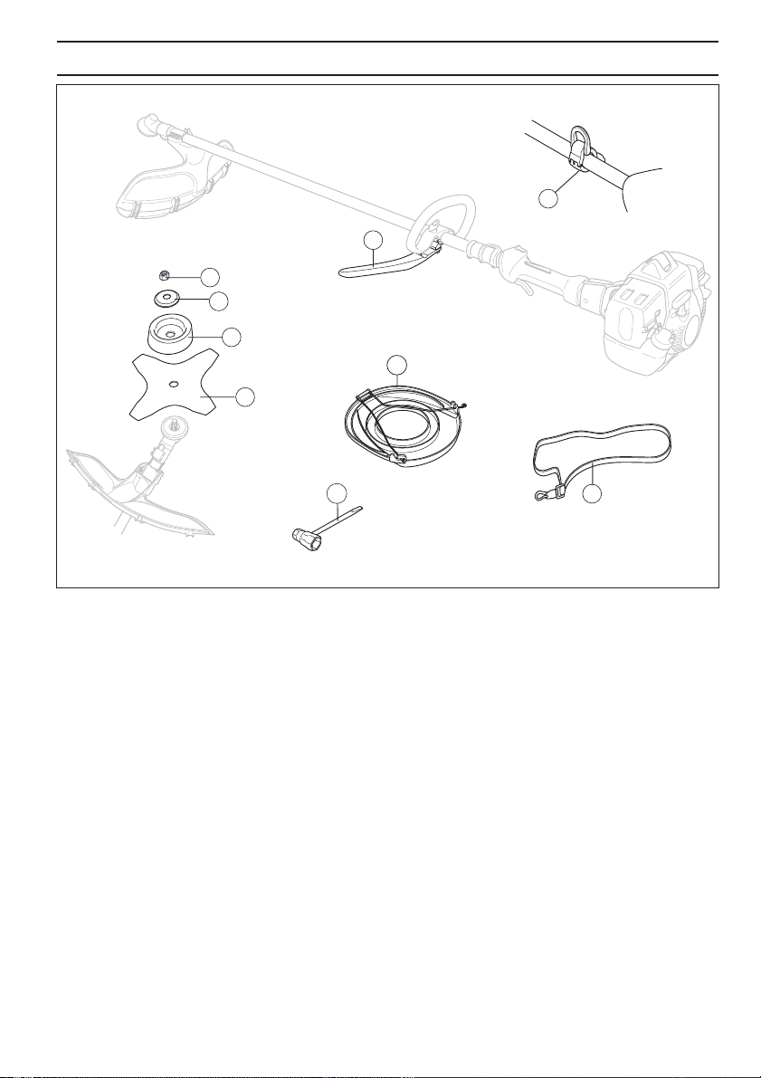
What is what?
6
7
8
1
2
3
4
5
9
1
Grass blade
2 Support cup
3 Support flange
4 Nut
5 J-handle
6 Transport guard
7 Socket spanner
8 Harness
9 Suspension ring
SAFETY INSTR
UCTIONS
4
–
English
Cutting equipment
This section descr
ibes how to choose and maintain your
cutting equipment in order to:
• Reduce the risk of kickback.
• Obtain maximum cutting performance.
• Extend the life of cutting equipment.
General rules
1
Only use cutting attachments with the guards we
recommend! See the chapter on Technical data.
2 Maintain the correct blade setting! Follow our
instructions and use the recommended blade setting
tool. An incorrectly set blade increases the risk of
jamming and blade thrust.
3 Check the cutting attachment for damage or cracks. A
damaged cutting attachment should always be
replaced.
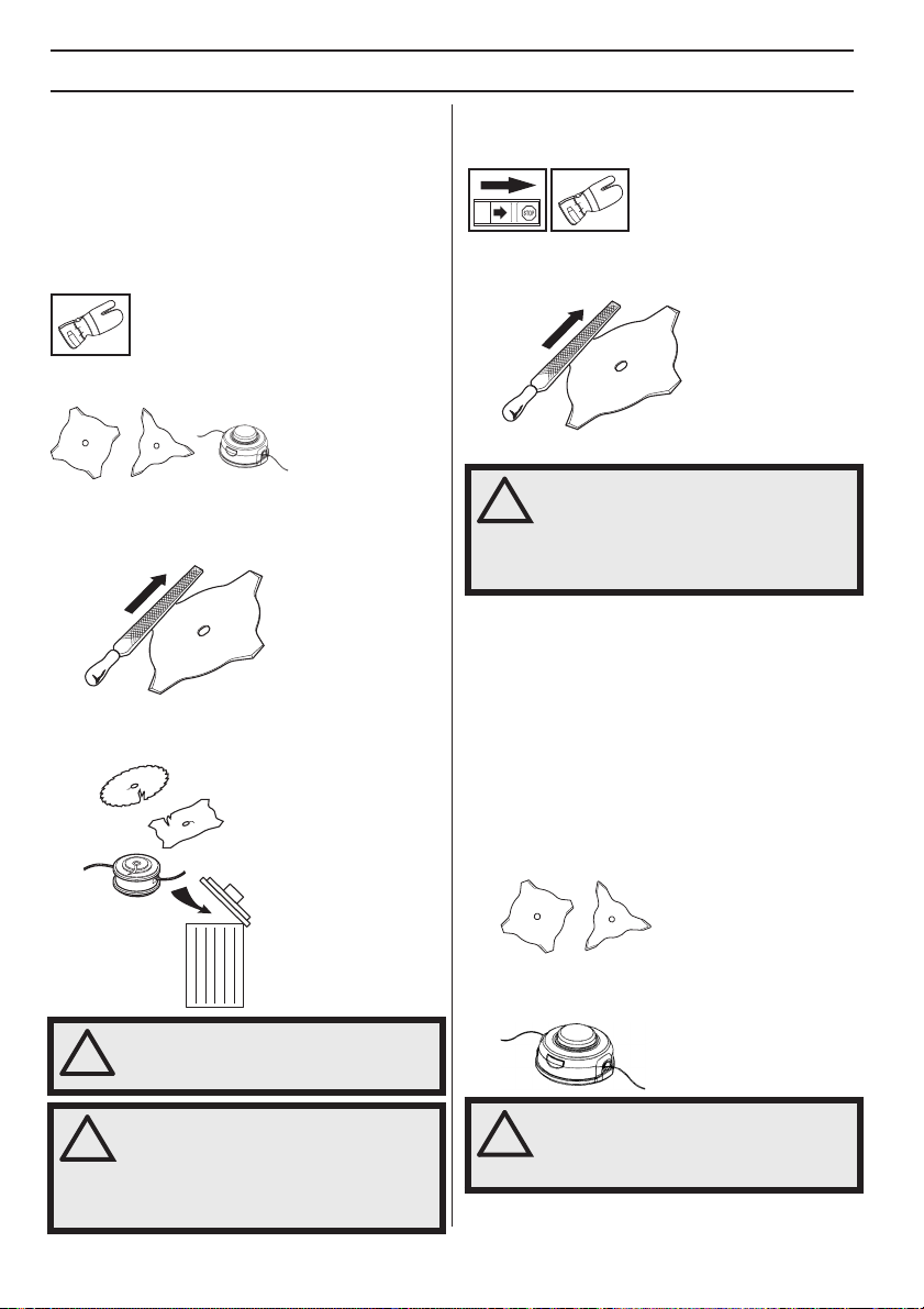
Sharpening grass knif
es and
grass blades
•
See the cutting attachment packaging for correct
sharpening instructions. Sharpen blades and cutters
using a single-cut flat file.
• Sharpen all edges equally to maintain blade balance.
General w
orking instructions
•
Always carry out clearing and trimming at full throttle.
• Always slow the engine to idle speed after each
working operation. Long periods at full throttle without
any load on the engine (i.e. without the resistance that
the cutting attachment exerts on the engine when you
are using the machine) can lead to serious engine
damage.
T
erms
•
Brush cutting is a general term for clearing grass.
Grass blades and grass cutters are used for this
purpose.
• Grass trimming is a general term for light clearing, e.g.
around edges or around trees. A trimmer head or
plastic blades are used.
!
W
ARNING! Using an incorrect cutting
attachment or an incorrectly sharpened
blade increases the risk of blade thrust.
!
W
ARNING! Avoid cutting with the area of
the blade between the 12 o’clock and 3
o’clock positions. Because of the speed
of rotation of the blade, blade thrust can
occur if you attempt to cut thick stems
with this area of the blade.
!
W
ARNING! Always discard a blade that is
bent, twisted, cracked, broken or
damaged in any other way. Never attempt
to straighten a twisted blade so that it
can be reused. Only use original blades
of the specified type.
!
W
ARNING! Sometimes branches or
grass get caught between the guard and
cutting attachment. Always stop the
engine before cleaning.
SAFETY INSTR
UCTIONS
English
–
5
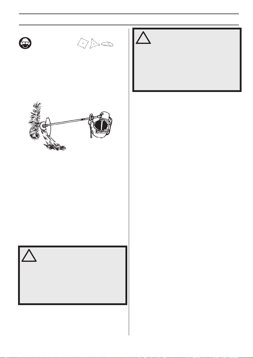
Grass c
learing using a grass blade
•
Grass blades and grass knifes must not be used on
woody stems.
• A grass blade is used for all types of tall or coarse
grass.
• The grass is cut down with a sideways, swinging
movement, where the movement from right-to-left is
the clearing stroke and the movement from left-to-
right is the return stroke. Let the left-hand side of the
blade (between 8 and 12 o’clock) do the cutting.
• If the blade is angled to the left when clearing grass,
the grass will collect in a line, which makes it easier to
collect, e.g. by raking.
• Try to work rhythmically. Stand firmly with your feet
apart. Move forward after the return stroke and stand
firmly again.
• Let the support cup rest lightly against the ground. It
is used to protect the blade from hitting the ground.
• Reduce the risk of material wrapping around the blade
by following these instructions:
1Always work at full throttle.
2Avoid the previously cut material during the return
stroke.
• Stop the engine, unclip the harness and place the
machine on the ground before you start to collect the
cut material.
!
W
ARNING! Neither the operator of the
machine nor anyone else may attempt to
remove the cut material while the engine
is running or the cutting equipment is
rotating, as this can result in serious
injury.
Stop the engine and cutting equipment
before you remove material that has
wound around the blade shaft as
otherwise there is a risk of injury.
!
W
ARNING! Watch out for thrown objects.
Always wear approved eye protection.
Never lean over the cutting attachment
guard. Stones, rubbish, etc. can be
thrown up into the eyes causing
blindness or serious injury.
Keep unauthorised persons at a
distance. Children, animals, onlookers
and helpers should be kept outside the
safety zone of 15 m. Stop the machine
immediately if anyone approaches.
ASSEMBL
Y
6
–
English
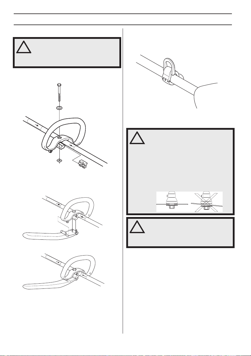
Fitting the J-handle
•
Clip the loop handle onto the shaft. Note that the loop
handle must be fitted between the arrows on the shaft.
• Slide the spacer into the slot in the loop handle.
• Fit the nut, washer and screw. Do not overtighten.
• Attach the J-handle to the loop handle using the two
screws, as shown.
Now carry out fine adjustment to give yourself a
comfortable working position. Tighten the screws.
Fitting the suspension ring
Fit the suspension r
ing between the rear handle and the
loop handle. Position the hanging ring so that the machine
is balanced and comfortable to work with.
Assemb
ling the cutting
equipment
!
W
ARNING! Only grass blades/grass
cutters or trimmer heads/plastic blades
may be used when the J-handle is fitted.
Saw blades must never be used with the
J-handle.
!
W
ARNING!
When fitting the cutting attachment it is
extremely important that the raised
section on the drive disc/support flange
engages correctly in the centre hole of
the cutting attachment. If the cutting
attachment is fitted incorrectly it can
result in serious and/or fatal personal
injury.
!
W
ARNING! Never use a cutting
attachment without an approved guard.
See the chapter on Technical data. If an
incorrect or faulty guard is fitted this can
cause serious personal injury.
ASSEMBL
Y
English
–
7
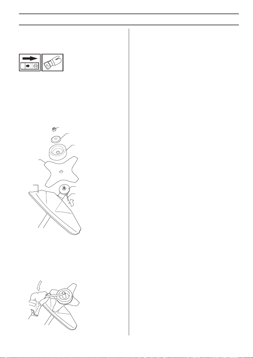
Fitting the b
lade guard/
combination guard, grass blade
and grass cutter
•
Hook the blade guard/combination guard (A) onto the
fitting on the shaft and secure with the bolt.
CAUTION!
Use the recommended blade guard. See
the Technical data section.
• Fit the drive disc (B) on the output shaft.
• Turn the output shaft until one of the holes in the drive
disc aligns with the corresponding hole in the gear
housing.
• Insert the locking pin (C) in the hole to lock the shaft.
• Place the blade (D), support cup (E) and support
flange (F) on the output shaft.
• Fit the nut (G). The nut must be tightened to a torque
of 35-50 Nm (3.5-5 kpm). Use the socket spanner in
the tool kit. Hold the shaft of the spanner as close to
the blade guard as possible. To tighten the nut, turn
the spanner in the opposite direction to the direction
of rotation (Caution! left-hand thread).
G
F
D
B
C
A
E
ST
AR
TING AND ST
OPPING
8
–
English
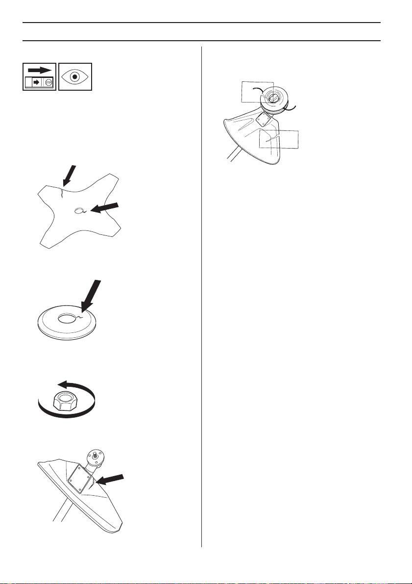
Chec
k before starting
F
or safety reasons follow these recommendations!
• Check the blade to ensure that no cracks have formed
at the bottom of the teeth or by the centre hole. The
most common reason why cracks are formed is that
sharp corners have been formed at the bottom of the
teeth while sharpening or that the blade has been
used with dull teeth. Discard a blade if cracks are
found.
• Check that the support flange is not cracked due to
fatigue or due to being tightened too much. Discard
the support flange if it is cracked.
• Ensure the locking nut has not lost its captive force.
The nut lock should have a locking force of at least 1.5
Nm. The tightening torque of the locking nut should be
35-50 Nm.
• Check that the blade guard is not damaged or
cracked. Replace the blade guard if it is exposed to
impact or is cracked.
• Check that the trimmer head and trimmer guard are
not damaged or cracked. Replace the trimmer head or
trimmer guard if they have been exposed to impact or
are cracked.
• Never use the machine without a guard nor with a
defective guard.
• All covers must be correctly fitted and undamaged
before you start the machine.

English
–
9
TECHNICAL D
ATA
Technical data
Approved accessories
Arbor shaft thread M10
Centre hole in blades/cutters, Ø 25,4 mm
Terms Type Cutting attachment guard, Art. no.
Grass blade/grass cutter Grass 255-4 1" (Ø 255 4-teeth) 503 93 42-02
Plastic blades Tricut Ø 300 mm 503 93 42-02
Trimmer head
S35 503 93 42-02
T35 503 93 42-02
Superauto II 1" 503 93 42-02
Trimmy Fix 503 93 42-02
Support cup Fixed
Loading...