


FS 410 D

FR
GB
DE
IT
ES
NL
SE
PT
Manuel d’utilisation - Lire attentivement et bien assimiler le manuel d’utilisation
avant d’utiliser la machine.
Operator’s manual - Please read the operator’s manual carefully and make sure
you understand the instructions before using the machine.
Bedienungsanweisung - Lesen Sie die Bedienungsanweisung sorgfältig durch
und machen Sie sich mit dem Inhalt vertraut, bevor Sie das Gerät benutzen.
Istruzioni per l’uso - Prima di usare la macchina, leggere per intero le istruzioni
per l’uso e accertarsi di averne compreso il contenuto.
Manual de instrucciones - Lea detenidamente el manual de instrucciones y
asegúrese de entender su contenido antes de utilizar la máquina.
Gebruiksaanwijzing - Neem de gebruiksaanwijzing grondig door en gebruik de
machine niet voor u alles duidelijk heeft begrepen.
Bruksanvisning - Läs igenom bruksanvisningen noggrant och förstå innehållet
innan du använder maskinen.
Instruções para o uso - Leia as instruções para o uso com toda a atenção e
compreenda o seu conteúdo antes de fazer uso da máquina.
HUSQVARNA CONSTRUCTION PRODUCTS
FS 410 D

2
CONTENTS and INTRODUCTION
Contents
Section Page
Contents & Introduction................................................ 3
Symbols and Decals....................................................4-8
Safety Instructions.....................................................9-13
Parts Identication (What Is What).........................14-15
Assembly................................................................ 16-20
Operation ................................................................ 21-25
Maintenance & Lubrication ................................... 27-28
Trouble Shooting Guide............................................... 29
Wiring diagram............................................................. 30
Technical Data......................................................... 31-32
Accessories.................................................................. 33
Conformity Certicates.................................................34
WARNING!
Before operating machine, read and understand this entire operation manual & engine
operation manual supplied with engine.
Be familiar with machine before operation!
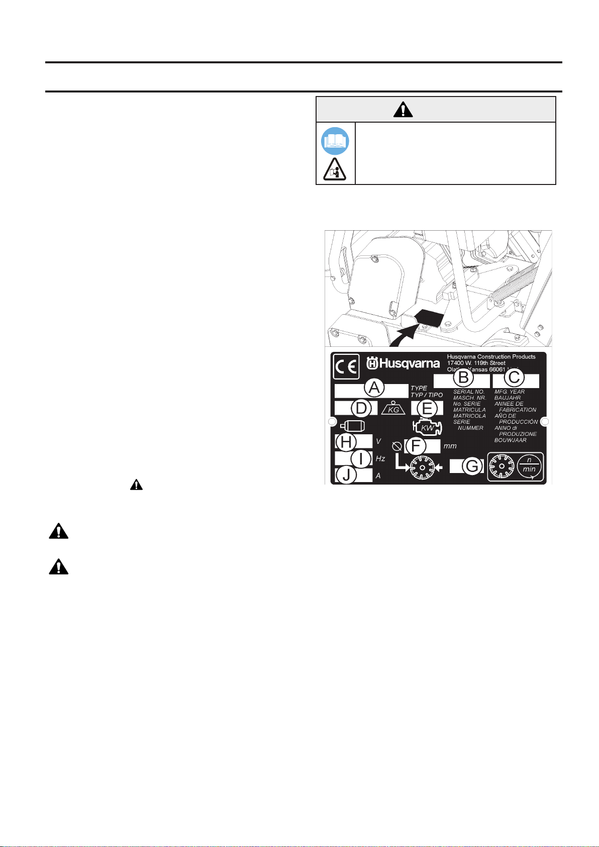
Model Identication: Record machine serial number
plate information below for future reference
Contact Information.......................................................35
Introduction
Thank you for purchasing your new machine from Husqvarna Construction Products. We have provided important
safety messages in this manual and on the machine.
Please read these messages carefully. A safety message
alerts you to potential hazards that could hurt you or others. Each safety message is preceded by a symbol or the
safety alert symbol (
or CAUTION.
These signal words mean:
WARNING: Indicates a hazardous situation which,
if not avoided COULD result in death or serious injury.
CAUTION: Indicates a hazardous situation, which,
if not avoided, COULD result in minor or moderate injury.
It may also be used to alert against unsafe practices.
Each message tells you what the hazard is, what can happen, and what you can do to avoid or reduce injury. Other
important messages are preceded by the word NOTICE.
NOTICE means:
NOTICE: Indicates a hazardous situation which, if not
avoided, could result in property damage. Your machine
or other property can be damaged if you don’t follow this
instruction.
The safety labels should be periodically inspected and
cleaned by the user to maintain good legibility at a safe
viewing distance. If the label is worn, damaged, or is illegible, it should be replaced.
) and one of two words, WARNING,
A. Model:______________________________________
B. Machine Serial No:____________________________
C. Year of Manufacture ___________________________
D. Mass of Machine (kg) __________________________
E. Engine Power (KW) ___________________________
F. Blade Diameter (mm) __________________________
G. Blade Speed (Revolutions / Minute) _______________
H. Electric Motor Voltage (If Equipped) _______________
I. Electric Motor Phase (If Equipped) _________________
J. Electric Motor Amperage (if Equipped) _____________
Other information not shown on machine serial plate:
Engine Serial No: _______________________________
See Engine Operation Manual for location.
Purchase Date:_________________________________
3
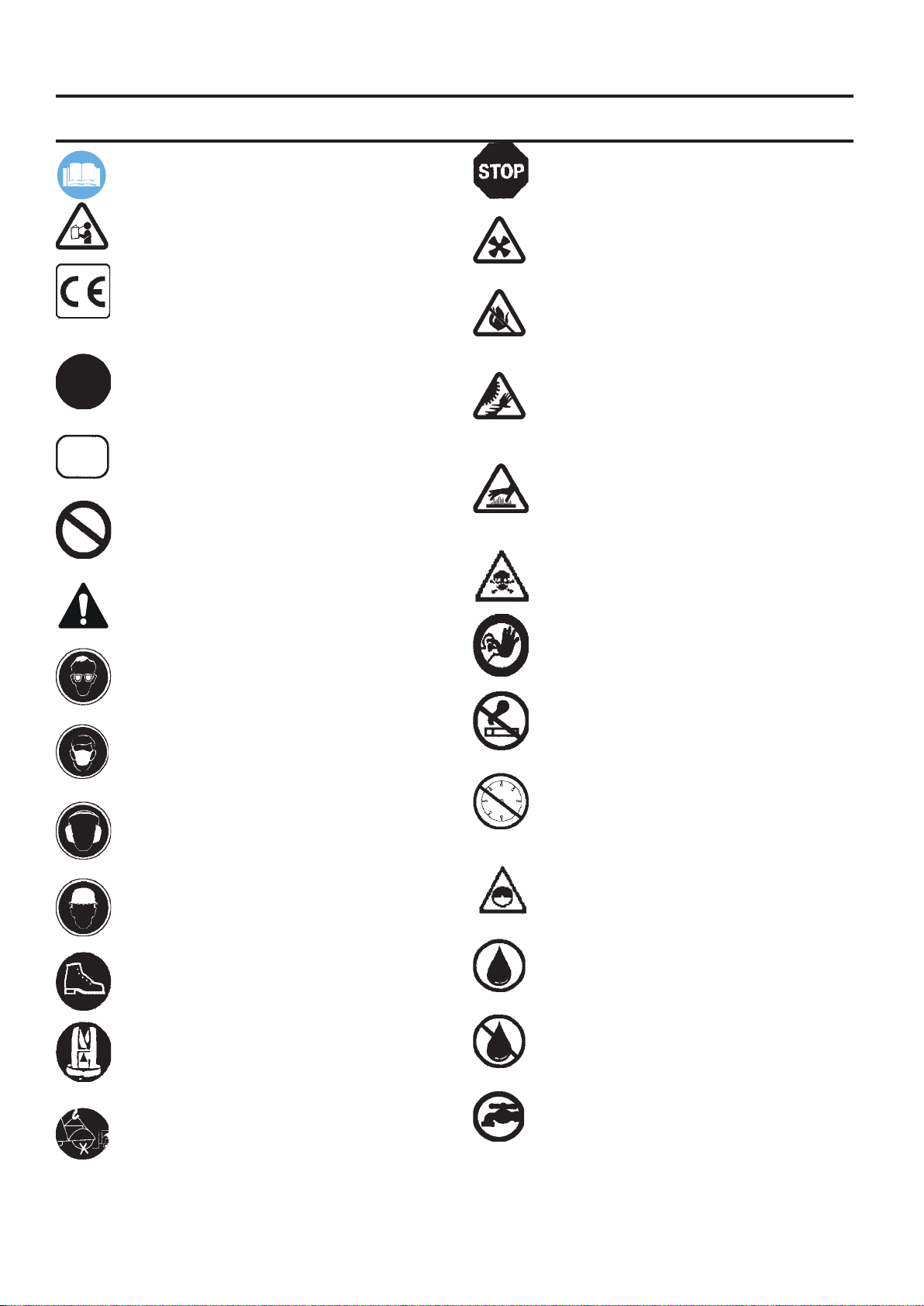
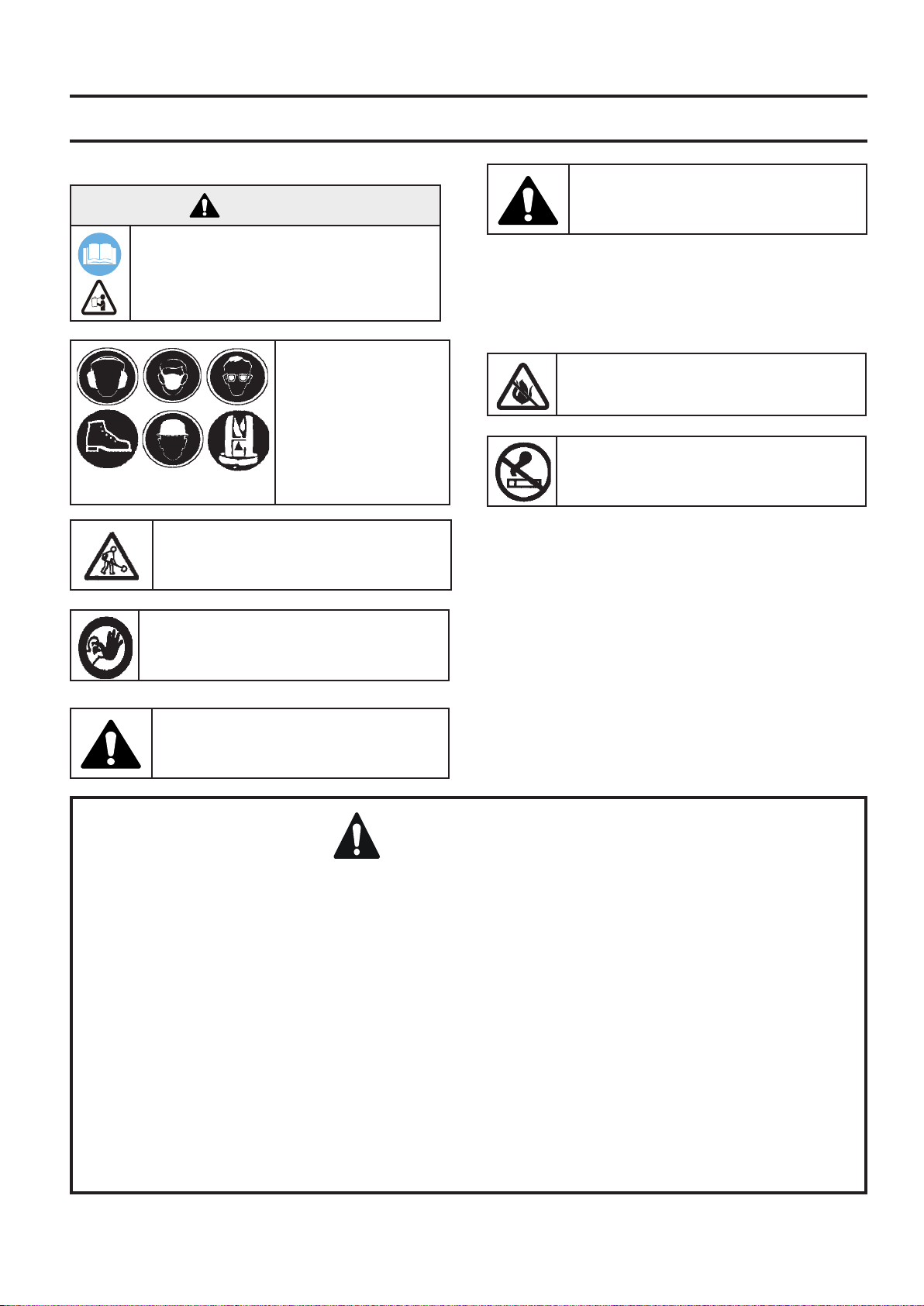
SYMBOLS and DECALS
Please read the instructions for use prior to
operating the machine for the rst time.
This symbol indicates that the machine is in
conformance with the applicable European
directive.
Mandatory
Indication
Prohibition
Warning Triangle
Emergency Shutdown, Transmission Stop
Use In Well Ventilated Area
Do Not Use In Flammable Areas
Machinery Hazard, Keep hands and Feet
Clear.
Mufer Hot. May Cause Burns and / or
Ignition of Material. Avoid Contact.
Danger, Poison Exhaust Gas
Wear Eye Protection
Wear Breathing Protection
The use of hearing protection is mandatory
Wear Head Protection
Wear Safety Shoes
Wear Appropriate Clothing
No Non-working Personnel In Area
No Smoking
Do Not Operate Without Blade Guard in
Place
Always Keep All Guards In Place
Water Supply On
Water Supply Off
Remove the blade prior to Hoisting, Loading,
Unloading and Transporting the Machine.
4
Water Supply

SYMBOLS and DECALS
Blade Water Safety Switch
Engine Coolant Temperature
Keep Work Area Clean/Well Lit, Remove All
Safety Hazards
Dangerously High Noise Level
Pay Extreme Attention to The Care And
Protection Of The Machine Before Starting Up
Remove Tools From Area and Machine
Electrical Switch-Start
Repairs Are To Be Done By An Authorized
Dealer Only
Headlight
Diamond Blade
Blade Diameter
Blade Engagement
Engine Oil Pressure
Oil Required
Dipstick, Maintain Proper Oil Level
Lubrication Point
High Speed
Low Speed
Pulley diameter
Number of Revolutions Per Minute, Rotational Speed
Blade Flange Diameter
Blade Depth Stop
Cutting Depth Indicator – Depth of Cut
Parking Brake
Electrical Switch-Off
Electrical Switch-On
Parking Brake Applied
Parking Brake Released
5
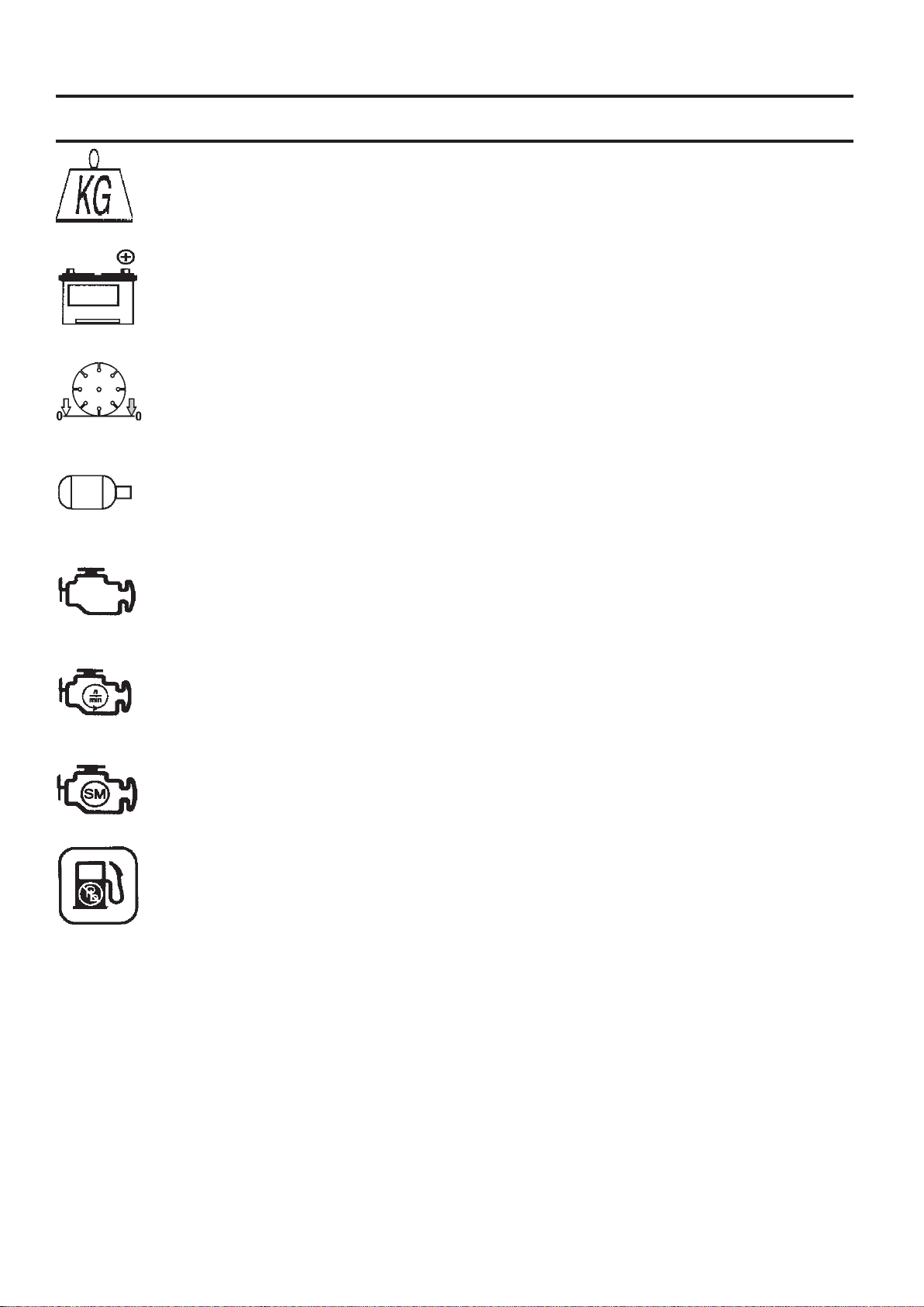
SYMBOLS and DECALS
Machine Mass (Kilograms)
Positive Battery Terminal
Blade Depth Indicator – Zero
Electric Motor
Engine
Engine Speed Revolutions/Minute
Engine Start
Unleaded Fuel Only
6

SYMBOLS and DECALS
P/N 542 19 07-33
Location: Front of Cowl
P/N 504 56 97-01
Location: Left and Right Side of Frame
(FS 410 D Only)
P/N 542 19 05-88
Location: Depth Gauge
P/N 542 19 06-46 Local Service
Location: Side of Frame
7
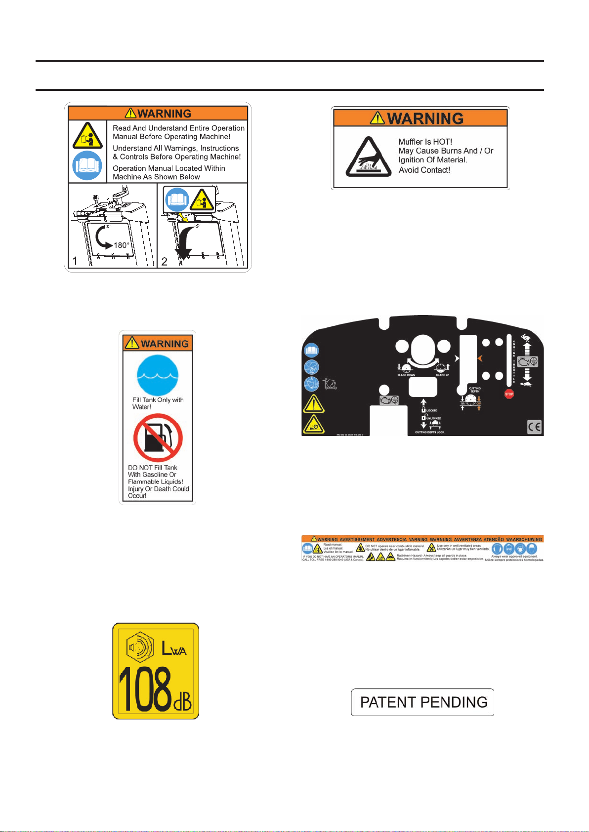
SYMBOLS and DECALS
P/N 542 19 05-93
Location: Rear of Cowl
P/N 542 16 90-65
Location: Top of Belt Guard
P/N 542 19 06-17
Location: Water Tank (If Equipped)
P/N 543 04 57-88 SOUND LEVEL - 108dBA
Location: Upper Righ Hand Frame
P/N 502 24 01-02
Location: Top of Cowl
P/N 542 19 06-38
Location: Rear of Cowl
P/N 542 16 12-35
Location: Upper Righ Hand Frame
8
SAFETY INSTRUCTIONS
General use
Before operating machine, read and understand this entire operation manual & engine
operation manual supplied with engine.
Be familiar with machine before operation!
Any persons not involved in the work,
should leave the area.
WARNING!
Operator must wear
personal protective
equipment & clothing appropriate to the
work he is doing.
Personal protective
equipment, such as
hearing & eye protection, is mandatory.
The working area must be completely
clear, well lit and all safety hazards
removed.
WARNING! Do not contact the tool when
machine is in operation.
Fuel Safety:
WARNING! Take care when handling
fuel. Bear in mind the risk of re, explosion and inhaling fumes.
• Only store fuel in containers approved for the purpose.
• Only refuel machine with engine OFF. Never remove fuel
cap and ll the fuel tank while the engine is running.
• Always refuel in a well ventilated area.
• Never ll a fuel tank indoors.
• Allow engine to cool before refueling.
Never fuel machine in vicinity of sparks or
ames. Do not use machine in ammable
area.
Do not smoke while fueling or using the
machine.
• Move machine 10 feet (3 meters) from refueling point
before starting engine.
• Never start the machine:
1) If fuel has been spilled on the machine. Wipe
off spillage and allow remaining fuel to evaporate.
2) If you have spilled fuel on yourself or your
clothes. Use soap and water to wash any part of
your body that has come in contact with fuel.
3) If the machine is leaking fuel. Check regularly
for leaks from the fuel cap and fuel lines.
• Store and transport machine and fuel so that there is
no risk of any leakage or fumes coming into contact with
sparks or ames, for example, electrical machinery or
electric motors, electrical relays / switches, or boilers.
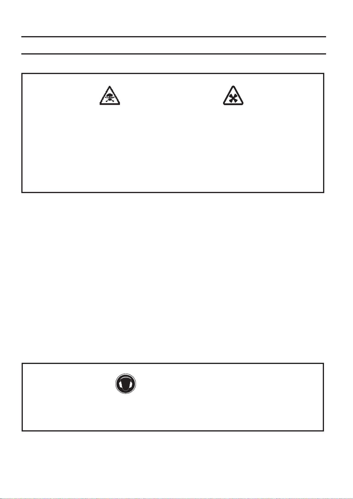
DUST WARNING
Cutting, especially when DRY cutting, generates dust that comes from the material being cut, which
frequently contains silica. Silica is a basic component of sand, quartz, brick clay, granite and numerous other
minerals and rocks. Exposure to excessive amount of such dust can cause:
• Respiratory diseases (affecting your ability to breath), including chronic bronchitis, silicosis and pulmo-
nary brosis from exposure to silica. These diseases may be fatal;
• Skin irritation and rash; and
• Cancer according to NTP* and IARC*
* National Toxicology Program, International Agency for Research on Cancer
Take precautionary steps
• Avoid inhalation of and skin contact with dust, mist and fumes;
• Wet cut when feasible, to minimize dust;
• Wear and ensure that all bystanders wear appropriate respiratory protection such as dust masks de-
signed to lter out microscopic particles. (See OSHA 29 CFR Part 1910.1200)
California Prop 65 Warning:
Use of this product can cause exposure to materials known to the State of California to cause cancer and/or birth
defects or other reproductive harm.
9
SAFETY INSTRUCTIONS
WARNING
POISON EXHAUST GAS
THIS SAW IS SHIPPED FROM THE FACTORY WITHOUT A CATALYTIC CONVERTER.
THE ENGINE PRODUCES CARBON MONOXIDE EXHAUST EMISSIONS AND IS NOT SAFE FOR USE IN
ENCLOSED AREAS. USE OF A CATALYTIC CONVERTER REDUCES THE CARBON MONOXIDE EXHAUST
EMISSIONS, BUT STILL IS NOT SAFE FOR USE IN ENCLOSED AREAS.
USE ONLY IN WELL-VENTILATED AREAS. WORKSITE AIR QUALITY MUST COMPLY WITH
OSHA 29 CFR 1910.1000 PER TABLE Z-1, LIMITS FOR AIR CONTAMINANTS.
MONITOR WORKSPACE AIR QUALITY TO INSURE COMPLIANCE. FAILURE TO COMPLY WILL RESULT IN
DANGER TO LIFE AND CAUSE PERMANENT INJURY OR DEATH.
General Information
Carbon monoxide (CO) has the distinction of being one of the few commonly encountered industrial gasses that is
both highly toxic (poison) and odorless. When inhaled, CO acts as a chemical asphyxiant by preferentially combining with hemoglobin in the blood stream. As a result, the hemoglobin is not able to transport its normal amount of
oxygen, which results in under-oxygenation of tissues. Symptoms of low-level CO exposure include headaches,
dizziness, confusion, and nausea. However, loss of consciousness, permanent injury and death may result
from continued or more intense exposure. Because of the health hazards associated with CO inhalation, the Occupational Safety and Health Administration (OSHA) have imposed personal exposure limits. The OSHA exposure
limits, which are specied in the 29 CFR 1910.1000 (1998 Revision), allow for a 200 PPM Ceiling Limit and a TWA
of 35 PPM per 8-hour shift/40-hr workweek. It is strongly recommended that the OSHA 29 CFR 1910.1000 (Code
of Federal Regulations) be consulted for more information on exposure limits for various hazardous materials. If CO
Poisoning is suspected immediately remove the victim to fresh air and obtain emergency medical attention.
Proper Ventilation:
THIS SAW IS SHIPPED FROM THE FACTORY WITHOUT A CATALYTIC CONVERTER. It is important to be aware
that saws with catalytic converters reduce CO and hydrocarbon (HC) emissions. The exhaust still contains CO. If the
workspace is too conned or under-ventilated, CO may accumulate until it eventually exceeds OSHA limits. When
this happens, action must be taken to remove workers from areas of high concentration. Operators and work area
supervisors should take precautions to insure adequate ventilation of the workspace at all times. Carbon monoxide
detection monitors should be used to determine that adequate ventilation exists.
WARNING
HEARING HAZARD
DURING NORMAL USE OF THIS MACHINE, OPERATOR MAY BE EXPOSED TO A NOISE
LEVEL EQUAL TO 85 dB (A) OR GREATER. TEMPORARY AND/OR PERMANENT DAMAGE TO HEARING
MAY RESULT. HEARING PROTECTION REQUIRED.
10

SAFETY INSTRUCTIONS
SAFETY FIRST!
WARNINGS
DO’s AND DO NOT’s
WARNING: FAILURE TO COMPLY WITH THESE WARNINGS AND OPERATING
INSTRUCTIONS COULD RESULT IN DEATH OR SERIOUS BODILY INJURY.
DO
DO Read this entire operator’s manual before operating this machine. Read and understand all warnings, instruc-
tions, controls, and symbol denitions contained in this manual, and on the machine.
DO always give a copy of this manual to the equipment user. If you need extra copies, call TOLL FREE
1-800-288-5040 in USA, or +1-913-928-1300 for International, or see “contact information” section of this
manual.
DO keep all guards in place and in good condition.
DO wear safety approved hearing, eye, head and respiratory protection.
DO read and understand all warnings and instructions on the machine.
DO keep all parts of your body away from the blade and all other moving parts.
DO know how to stop the machine quickly in case of emergency.
DO shut off the engine and allow it to cool before refueling or doing maintenance.
DO inspect the blade, anges and shafts for damage before installing the blade.
DO use the blade ange size shown for each blade size.
DO use only steel center diamond blades manufactured for use on concrete saws.
DO use only the blade anges supplied with the saw. Never use damaged or worn blade anges.
DO use only blades marked with a maximum operating speed greater than the blade shaft speed. Verify speed by
checking blade shaft rpm and pulley diameters and blade ange diameters.
DO verify saw drive conguration by checking blade shaft RPM, pulley diameters, and blade ange diameter.
DO read all safety materials and instructions that accompany any blade used with this machine.
DO inspect each blade carefully before using it. If there are any signs of damage or unusual wear, DO NOT USE
THE BLADE.
DO mount the blade solidly and rmly, Wrench tighten the arbor nut.
DO make sure the blade and anges are clean and free of dirt and debris before mounting the blade on the saw.
DO use the correct blade for the type of work being done. Check with blade manufacturer if you do not know if
blade is correct.
DO use caution and follow the instructions when loading and unloading the machine.
DO operate this machine only in well ventilated areas. Breathing Poison Exhaust Gas could result in death.
DO instruct bystanders on where to stand while the machine is in operation.
DO establish a training program for all operators of this machine.
DO clear the work area of unnecessary people. Never allow anyone to stand in front of or behind the blade while
the engine is running.
DO make sure the blade is not contacting anything before starting the engine.
DO use caution when lifting and transporting this machine.
DO always tie down the machine when transporting.
DO use caution and follow instructions when setting up or transporting the machine.
DO have all service performed by competent service personnel
DO verify the blade arbor hole matches the machine spindle before mounting the blade.
DO always check for buried hazards, such as electrical or gas lines before sawing. Always contact local utilities
before operation in unknown areas.
DO move the machine at least 10 feet (3 meters) from the fueling point before starting the engine and make sure
the fuel cap is on the machine and properly tightened.
DO lift machine only from specied lifting point.
DO clean the machine after each day’s use.
DO use the proper blade ange size for each blade size. Never use damaged or worn blade anges.
DO use caution when handling fuel.
DO only cut in a straight line, and only saw as deep as the job specications require.
11

SAFETY INSTRUCTIONS
SAFETY FIRST!
WARNINGS
DO’s AND DO NOT’s
WARNING: FAILURE TO COMPLY WITH THESE WARNINGS AND OPERATING
INSTRUCTIONS COULD RESULT IN DEATH OR SERIOUS BODILY INJURY.
DO NOT
DO NOT
DO NOT operate this machine without the blade guard, or other protective guards in place.
DO NOT stand behind or in front of the blade path while the engine is running.
DO NOT leave this machine unattended while the engine is running.
DO NOT work on this machine while the engine is running.
DO NOT operate this machine when you are tired, fatigued or under the inuence of drugs or alcohol.
DO NOT use a wet blade without adequate water supply to the blade.
DO NOT exceed maximum blade speed shown for each blade size. Excessive speed could result in blade
DO NOT operate the machine if you are uncertain of how to run the machine.
DO NOT use damaged equipment or blades.
DO NOT touch or try to stop a moving blade with your hand.
DO NOT cock, jam, wedge or twist the blade in a cut.
DO NOT transport a cutting machine with the blade mounted on the machine.
DO NOT use a blade that has been dropped or damaged.
DO NOT use carbide tipped blades.
DO NOT touch a dry cutting diamond blade immediately after use. These blades require several minutes to cool
DO NOT use damaged or worn blade anges.
DO NOT allow other persons to be near the machine when starting, refueling, or when the machine is in
DO NOT operate this machine in an enclosed area. Breathing Poison Exhaust Gas could result in death.
DO NOT operate this machine in the vicinity of anything that is ammable. Sparks could cause a re or an
DO NOT allow blade exposure from the guard to be more than 180 degrees.
DO NOT operate this machine with the belt guards or blade guard removed.
DO NOT operate this machine unless you are specically trained for its operation.
DO NOT use a blade that has been over heated (Core has a bluish color).
DO NOT jam material into the blade.
DO NOT grind on the side of the blade.
DO NOT tow this machine behind a vehicle.
DO NOT operate this machine with the any guards or shields removed.
DO NOT cut deeper than 1” (25mm) per pass with a dry blade. Step cut to achieve deeper cuts.
DO NOT operate this machine while under the inuence of drugs or alcohol.
operate this machine unless you have read and understood this operator’s manual.
breakage.
after each cut.
operation.
explosion.
*****************
This saw was designed for certain applications only. DO NOT modify this saw or use for any application other
than for which it was designed. If you have any questions relative to its application, DO NOT use the saw until
you have written Husqvarna Construction Products and we have advised you.
Husqvarna Construction Products North America
17400 West 119th Street, Olathe, Kansas 66061 USA
12

NOTES
13
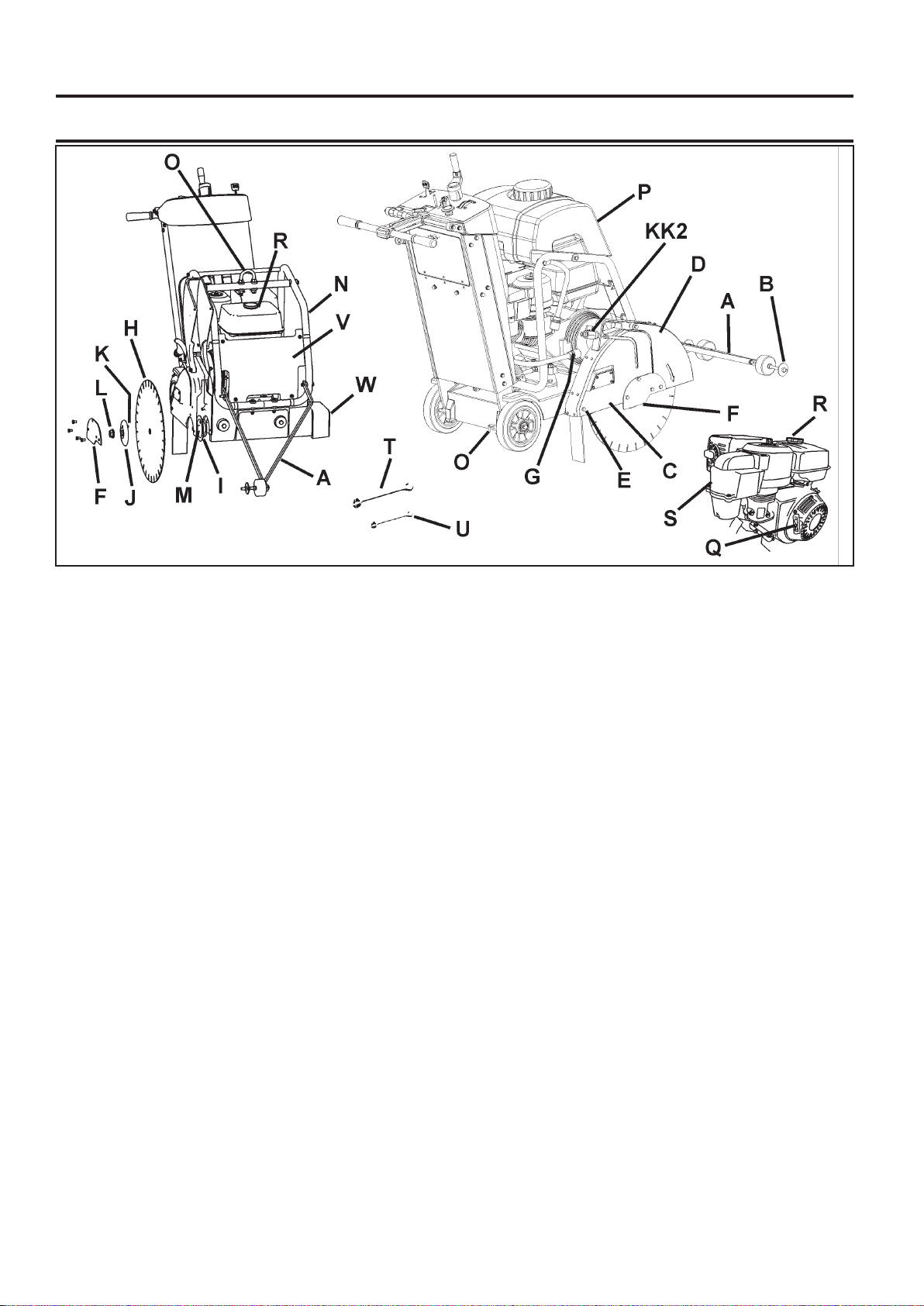
PARTS IDENTIFICATION (WHAT IS WHAT)
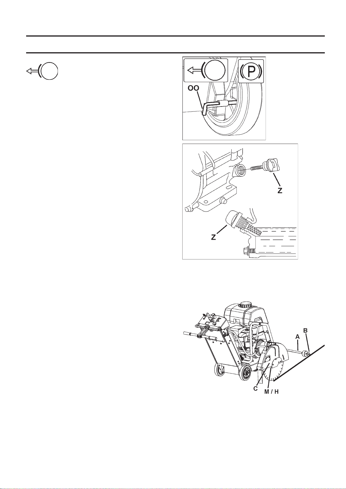
A. Front Pointer: Use to Guide machine in a straight line.
B. Guide Wheel: On Front Pointer (A). Align to cutting
line and Blade (H) to produce straight cuts.
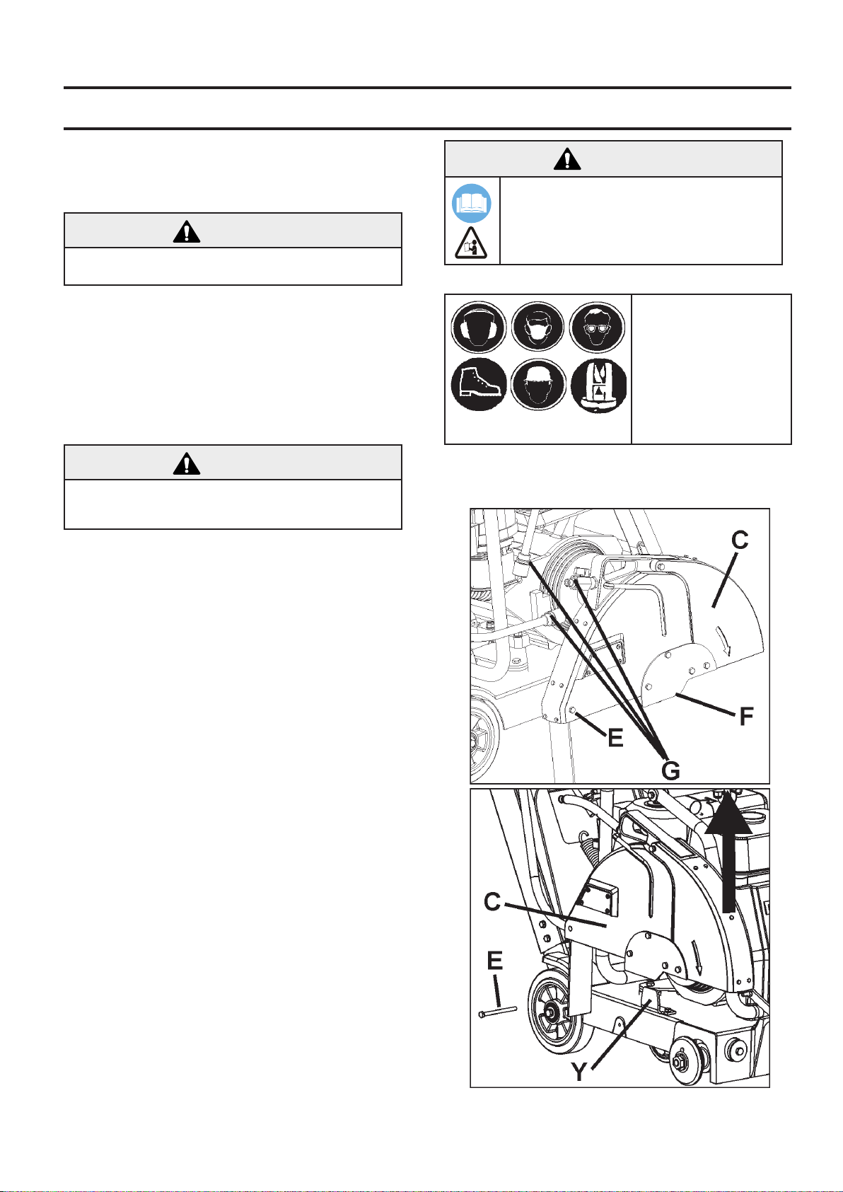
C. Blade Guard: Covers Blade (H). Must always be in
place when operating machine! Note tool direction as
marked on guard with an arrow.
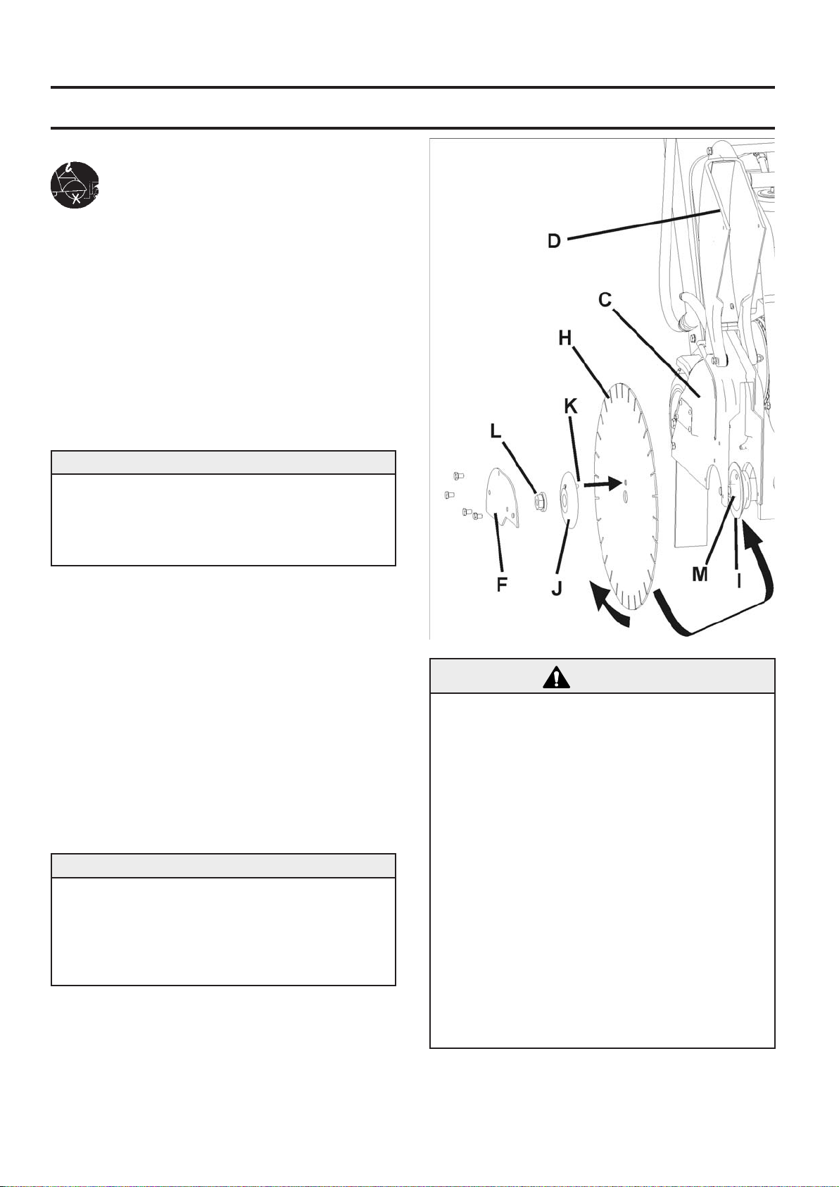
D. Blade Guard Front: Part of Blade Guard. Can be
raised to install Blade (H).
E. Blade Guard Rear Bolt: Holds Blade Guard (C) in
position. Must be removed and relocated if Blade Guard
(C) is moved.
F. Blade Guard Latch Plate: Covers Outer Flange (J).
G. Water Hose Disconnect (G): Connects Blade Guard
(C) to Water Control Valve (KK) or Water Tank (P). Can
be used when Blade Guard (C) is mounted to left or right
side of machine
H. Blade: Tool that cuts asphalt or concrete material – not
included with machine.
I. Inner Flange: Arbor on which the Blade (H) is mounted.
Replace if Damaged or worn.
J. Outer Flange: Used to hold Blade (H) in position.
Contains Locking Pin (K) that must go through Blade (H).
Replace if damaged or worn.
K. Locking Pin: Holds Blade (H) in position. Replace if
Damaged or worn.
L. Blade Shaft Nut (L1 / L2): Holds Outer Flange (J) to
machine. Nut (L1) on right side of machine has Left Hand
threads. Nut (L2)(not shown) on left side of machine has
Right Hand threads.
M. Blade Arbor: Blade (H) mounts on this surface.
N. Water Tank / Lifting Point Support: Holds Water Tank
(P). Supports Lifting Point (O).
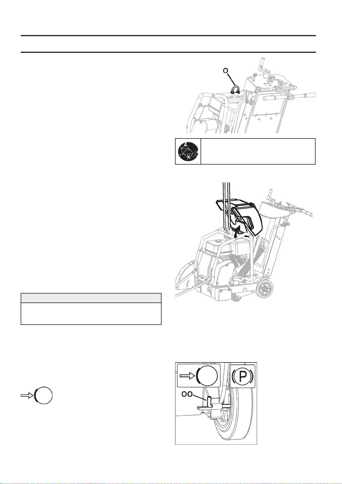
O. Lifting Point: Lift machine only from this point!
P. Water Tank (If Equipped):
water capacity. Fill only with water! Do not ll with gasoline or other ammable substances! Use only for dust
suppression when cutting dry. Use only with laser welded
(dry) Diamond Blades (H).
Q. Engine Starting Rope: Use to start engine. See engine operation manual.
R. – – –
S. – – –
T. Blade Shaft Wrench (27mm): Use for installing and
removing Blade (H). Store in Tool Compartment (BB).
U. Wrench (13mm): Use for many maintenance items on
machine. Store in Tool Compartment (BB).
V. Front Cover: Clips to Water Tank Support (N).
W. Shaft Guard: Protects Inner Flange (I). Always in-
stalled on opposite side of frame to Blade Guard (C).
X. Depth Control Grease Fitting: Not Shown. See Main-
tenance section of this document.
Y. Blade Guard Mounting Spade: Holds Blade Guard
(C) in position.
Z. Engine Oil Dipstick: Use to check engine oil level (Not
Shown – See Operation Section of this document).
25 Liter (6.6 U.S. Gallon)
14

PARTS IDENTIFICATION (WHAT IS WHAT)
BB
JJ
CC
EE
HH
KK1
FF
GG
AA. – – –
BB. Tool Compartment: Contains Operation Manual,
Parts List, & two wrenches (T & U) (13mm & 27mm).
Open by turning knob 180 degrees. Always return Operation Manual to this area for future reference.
CC. Engine Throttle: Controls Engine speed (RPM).
Push forward to increase engine speed. Pull backwards
to decrease engine speed. All sawing is done at maximum engine speed.
DD. – – –
EE. Blade Depth Control: Turn Counter-Clockwise to
raise Diamond Blade (H) and Clockwise to lower Diamond
Blade (H).
FF. Blade Depth Stop: To Lock Blade Depth Control (EE)
in position. Pull Blade Depth Stop toward rear of machine
and turn 90 degrees to lock in open position.
GG. Blade Depth Indicator: Shows cutting depth of Diamond Blade (H) in centimeters (orange color) and inches
(white color). Operation: With engine OFF (“0”), lower
Diamond Blade (H) until in contacts the cutting surface.
Rotate Blade Depth Indicator to align “0” with arrows.
Raise Saw. When saw is lowered into cut, current cutting
depth is shown.
HH. Engine Tachometer (RPM): Shows engine speed in
revolutions per minute if engine is running. Shows total
operation time when engine is OFF (“0”). Total operation
time shown in minutes from 0-59 minutes, and hours for
60+ minutes.
II. – – –
JJ. Rear Handle: Operator position is behind machine
with both hands on Rear Handle. Handle is adjustable to
several positions.
KK1. Water Control Valve: Controls water ow to blade.
Located on Left side of machine, near Rear Handle (RR).
Not used with the water tank (if equipped).
KK2. Blade Guard Water Control Valve: Controls the
water ow to the blade. Located on blade guard. Used
with water tank (if equipped).
LL. Belt Guard (Not Shown): Covers engine drive belt.
MM. Belt Drive Idler: Used to hold tension on Blade
Shaft Drive Belt.
NN. Oil Drain Hose: Use to remove oil from engine.
OO. Parking Brake (EU units only): Use to hold ma-
chine in parked position. Located at Right Rear Wheel,
at rear of machine. Operation: To engage, rotate lever
upward, so rod is allowed to move inward. To dis-engage,
pull rod inward and rotate downward so rod is xed in the
inward position.
15
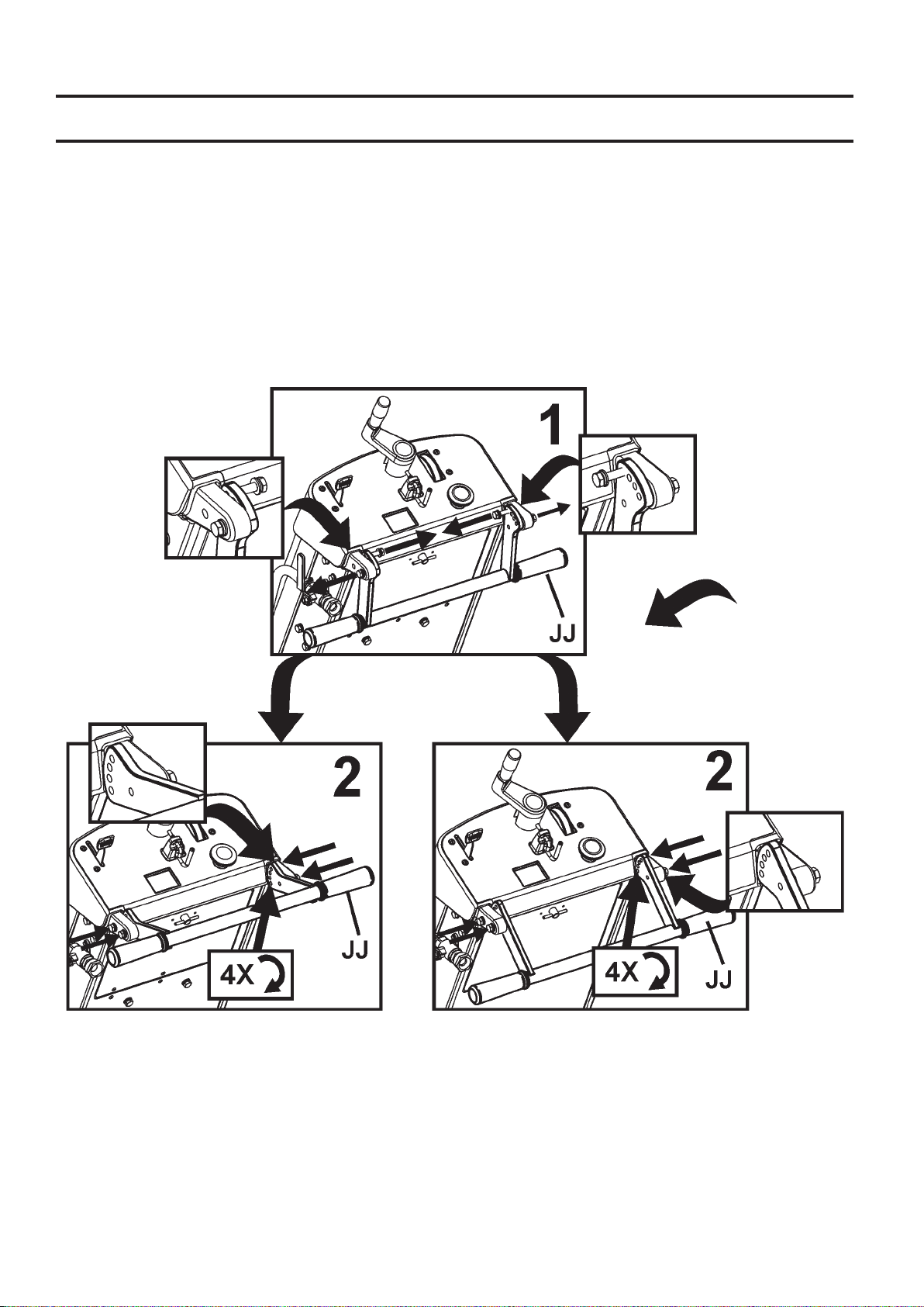
ASSEMBLY
Assemble the following items before operating machine
for the rst time.
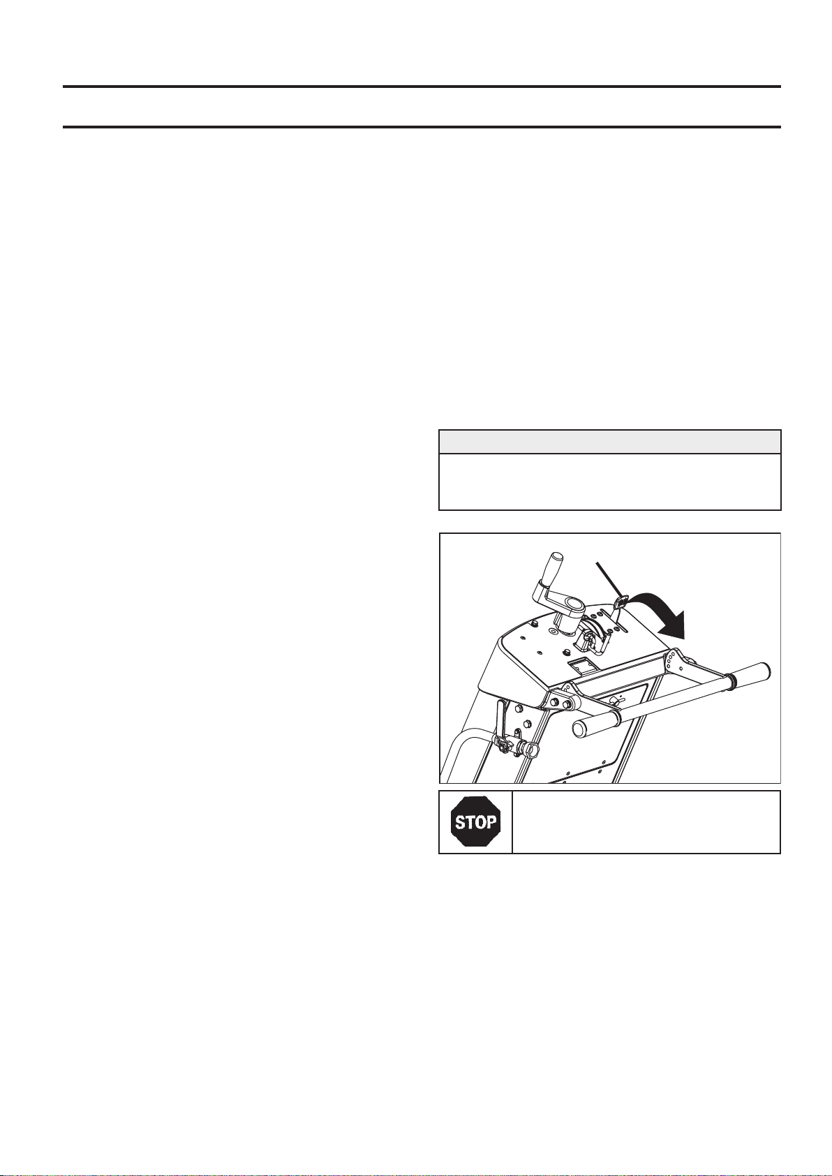
Re-Position Rear Handle (JJ): Rear Handle (JJ) is
shipped in storage position shown. It must be repositioned to use the machine.
16
ASSEMBLY
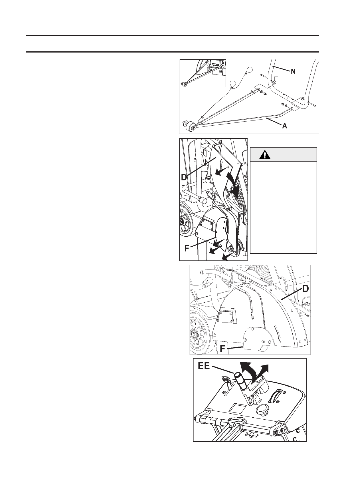
Install Front Pointer (A):
1. Using screws, washers and nuts installed in the Front
Pointer (A), install onto tube frame of Water Tank Support
(N). Adjust locking nuts to allow Pointer (A) to pivot freely.
2. Route pointer rope to avoid hot surfaces. Two loops in
rope allow attachment to Rear Handle (JJ).
Note: “Single Pointer” (A) shown. Some regions have
“Dual Pointer” as standard equipment. For all regions,
Dual Pointer is available as an accessory. See “accessories” section of this document, or spare parts list for more
information.
Blade Guard Front (D):
1. Using 13mm Wrench (U) provided, remove two (2) M8
screws located in front of and below Blade Guard Latch
Plate (F), and the M8 screw in Blade Guard Front (D) [as
indicated by arrows]. Lossen, but do not remove, remaining screw Blade Guard Latch Plate (F). Rotate Blade
Guard Latch Plate (F), and Blade Guard Front (D) downward.
2. Reinstall three (3) M8 screws in Blade Guard Latch
Plate (F) as shown in the diagram at the right. Use the
13mm Wrench (U) (supplied) to securely tighten the four
(4) M8 bolts that hold the Blade Guard Latch Plate (F) in
position.
WARNING!
Blade Guard Latch Plate
(F) Must Be Installed
before operation. Failure
to Install before operating
machine could create a
Hazardous situation!
Always keep all guards
in place when operating
machine!
Re-Position Blade Depth Control Handle (EE):
Pull outward on Blade Depth Control Handle (EE) and
rotate 90 degrees until is snaps in position shown.
17
ASSEMBLY
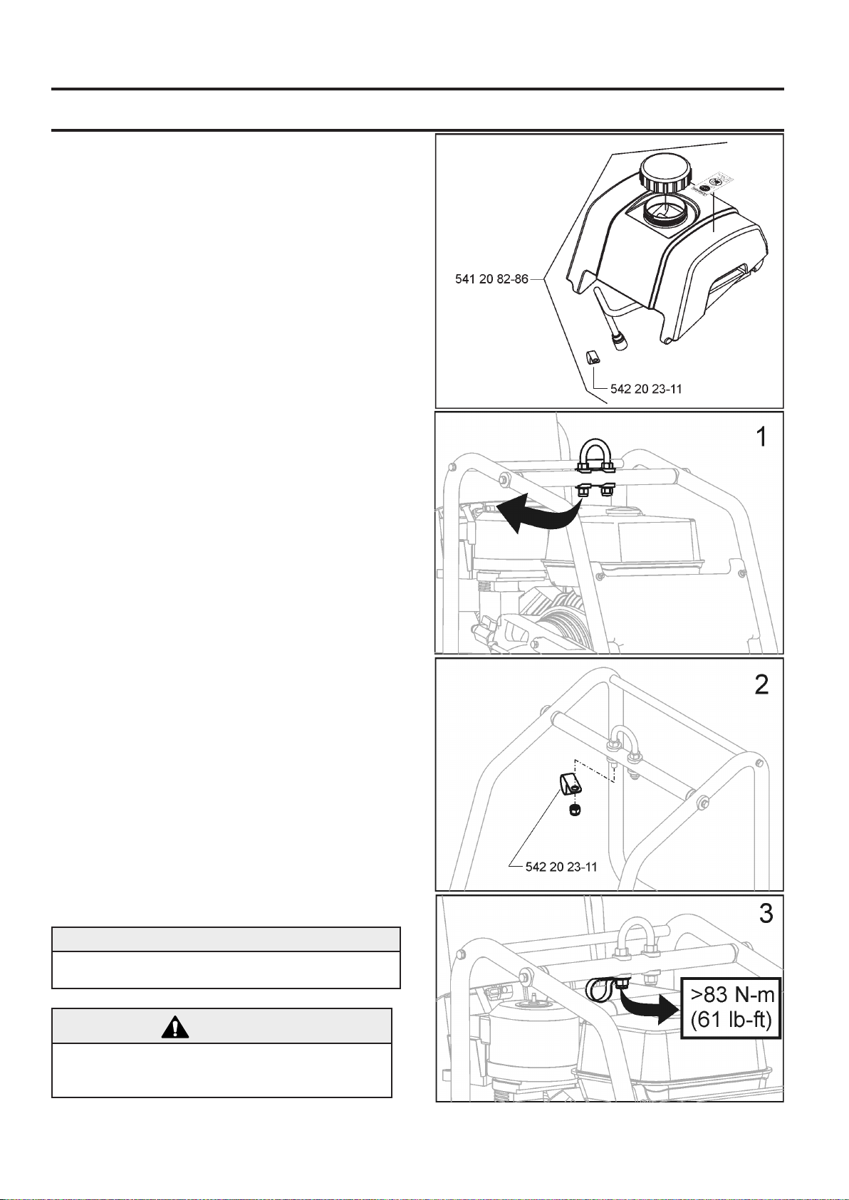
Install Water Tank (P) (if equipped):
• A factory installed water tank is available in some
regions. An optional water tank kit is available for all
regions.
• If water tank was previously installed on machine, read
these instructions to verify that installation is correct. Follow all WARNINGS for installation and use of the Water
Tank.
• Verify the contents of the Water Tank Kit See Diagram at
right.
1. Temporarily remove the right hand (same side of machine as engine starter rope) NUT from Lifting Eye (O).
See diagram at right.
2. Install CLAMP supplied in Water Tank Kit (P), and then
reinstall the NUT. See diagram at right.
3. Torque as specied below, and diagram at right.
NOTICE
Torque Lifting Eye NUT to 83 N-m (61 lb-ft) mini-
mum.
WARNING!
Torque NUT as specied, else failure of LIFTING EYE
(O) could occur. Injury or death could occur if LIFTING EYE fails while lifting machine.
18
ASSEMBLY
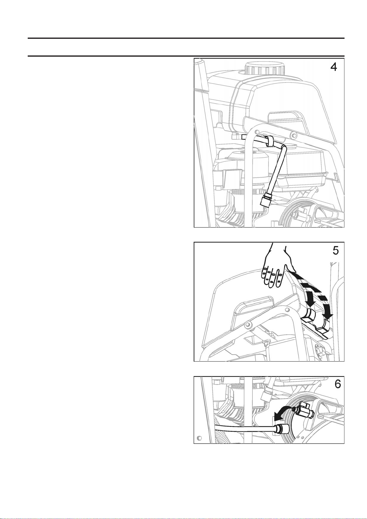
4. Position Water Tank, and route Water Tank Hose as
shown in Diagram at right.
5. Align rear bar and recessed area at rear of water tank.
• Press down rmly on water tank so it snaps in position
onto rear bar.
• When properly installed, water tank should pivot freely
on rear bar.
6. Disconnect existing water hose from blade guard.
This is the water hose from water control valve mounted
on saw.
19
ASSEMBLY
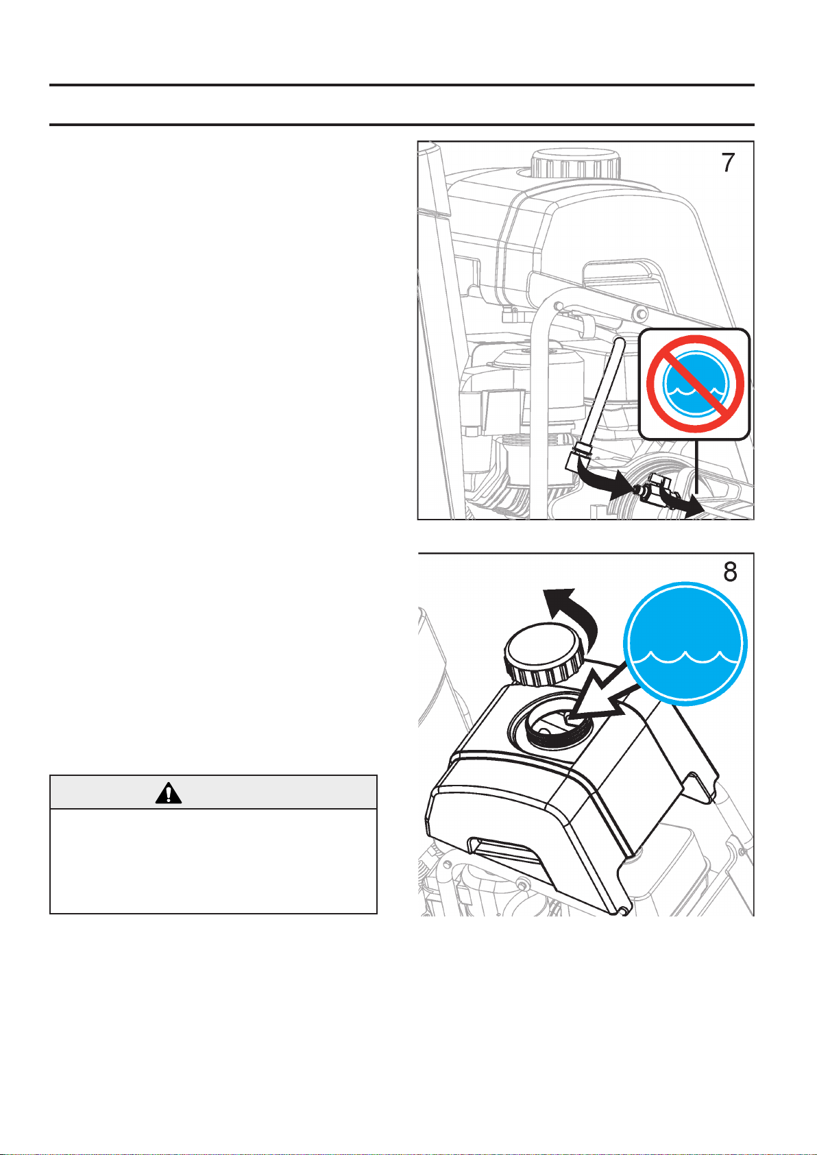
7. Connect Water tank hose to blade guard water valve.
• Verify that blade guard water valve is in the OFF position.
• The water tank hose is now assembled to the saw.
Filling Water Tank:
8. Remove the cap by turning counter clockwise. See
diagram at right.
• Fill water tank only with water. Read all WARNINGS
before using water tank.
• Re-install the cap by turning clockwise.
• Water tank is designed only to suppress airborne
concrete dust, and should only be used with “dry” cutting
diamond blades.
WARNING!
DO NOT use conventional (wet) diamond blades with
water tank as water source. Water ow is not sufcient to properly cool blade!
Fill Water Tank Only With Water!
Never ll Water Tank (P) with ammable liquids or
gasoline, else injury or death could occur!
20
OPERATION
Before Operation:
Use: This machine is used only for wet or dry sawing of
old and new concrete and asphalt.
WARNING!
DO NOT use for dry cutting in European Union (EU)
regions. Machine is not equipped with a dust port.
WARNING!
Before operating machine, read and understand this entire operation manual & engine
operation manual supplied with engine.
Be familiar with machine before operation!
Tools: Use machine only with the following tools (H): Water Cooled Diamond Blades. Reinforced Abrasive Blades
or Dry Cutting Diamond blades should NOT be used within European Union (EU) regions because this machine, as
supplied, does not include a dust collector port.
Diameter: 300 mm (12”) – 500 mm (20”).
Bore: 25.4mm (1.00”).
WARNING!
DO NOT use carbide, wood saw, or circular saw
blades on this machine, else injury or death could occur.
Re-Locating the Blade Guard (C) - If Required:
Blade Guard (C) is factory installed on right hand side of
machine, but can be relocated to left side. This may allow
cutting closer to obstacles, if approaching them from the
opposite direction is not possible.
1. Use 13mm Wrench (U) to remove Blade Guard Rear
Bolt (E) from Blade Guard (C).
2. Push back collar to separate Water Hose Disconnect
(G). Male half remains with Blade Guard (C). Female
half remains with Water Tank (P) or Water Control Valve
(KK).
3. Lift Blade Guard (C) upward, and off of Blade Guard
Mounting Spade (Y).
4. Use 13mm Wrench (U) to remove four (4) screws that
attach Blade Guard Latch Plate (F). Re-attach the Blade
Guard Latch Plate (F) to the left hand side of Blade Guard
(C).
5. Remove and relocate Shaft Guard (W) from left hand
side of machine to right hand side.
6. Lower Blade Guard (C) onto Blade Guard Mounting
Spade (Y) on left hand side of machine.
7. Re-Install Rear Bolt (E) in Blade Guard (C).
8. Re-Attach Water Hose Disconnect (G) from Blade
Guard (C) to Water Tank (P) or Water Valve (KK). Take
care that relocated hose will not contact mufer.
9. Relocate and realign Front Pointer (A) so Guide Wheel
(B) is on left side of machine.
Operator must wear
personal protective
equipment & clothing appropriate to the
work he is doing.
Personal protective
equipment, such as
hearing & eye protection, is mandatory.
21
OPERATION
Transporting & Lifting Machine:
• Lift machine only from Lifting Point (O).
• Always remove Blade (H) before lifting, loading, or transporting.
• Use a proper lifting strap rated for at least the maximum
mass of the machine. The nominal and maximum mass
of the machine are shown in the TECHNICAL DATA section of this document.
Lifting machine equipped with Water Tank:
• Before lifting a machine equipped with a water tank:
1. Empty water from tank.
2. Remove Blade.
3. Lower machine until frame is parallel to ground.
4. Pivot front of water tank upward until it rests against
aluminum cowl top. Do not rest water tank cap against
plastic cowl front - damage during lifting could occur.
5. Attach proper lifting strap to Lifting Point (O).
6. Test Lift machine at a low level (just a few centimeters)
to verify tank remains secured to machine, and will not be
damaged or cause damage.
7. If water tank equiped machine can not be lifted without
damage to the machine or tank, remove water tank before
lifting.
Remove Blade (H) before lifting, loading,
or transporting machine.
NOTICE
Water tank or saw could be damaged if saw is not
lifted properly. Closely monitor for damage while lifting
machine.
Parking Machine:
• Machines used in some regions are equipped with a
Parking Brake.
• Parking brake is designed to hold machine in position
on a slope of 10 degrees or less, with rear of machine
on downhill side of slope (maximum weight on braked
wheel).
Parking Brake - Engage (See Diagram):
Move parking brake lever (OO) from the
dis-engaged position:
1. Pull lever (OO) toward center of machine.
2. Rotate lever (OO) upward 180 degrees.
3. A spring allows lever (OO) to move toward outside of
machine, to engage against wheel hub.
22
OPERATION
Parking Brake - Dis-engage (See Dia
gram): Parking brake must be dis-engaged
to operate machine.
1. Pull lever (OO) toward center of machine.
2. Rotate lever (OO) downward 180 degrees and release
to lock in position.
Gasoline Engine Models:
Refer to the engine operating manual for proper engine
operation.
FUEL: See engine operation manual for more information.
OIL: Check that engine oil level is correct using the
Engine Oil Dipstick (Z). When checking the engine oil
level, the Engine Oil Dipstick (Z) should not be screw into
the port. Because the engine often operates at an angle,
check oil level with engine horizontal. Check frequently to
ensure that oil level never falls below lower mark on dipstick. 10W30 oil is recommended. See engine operation
manual for more information.
All Models:
Front Pointer (A) must be checked for alignment with
blade. Lay a straight edge along Inner Flange (I). Align
Front Pointer (A) to straight edge. If required, adjust Front
Pointer (A) by loosening nuts that hold Guide Wheel (B)
in place. Align Guide Wheel (B) to straight edge and retighten nuts.
Check that water tubing in the Blade Guard (C) is open
and that each side of blade has an adequate supply of
water.
Test the water supply for pressure and quantity (ow)
before starting the saw.
Saw only as deep as the job specications require. Saw-
ing deeper than required will add excessive wear the
blade and machine.
Cut in increments of 50mm (2 inches) deep until cutting
depth specication is reached. This is known as “step
cutting”.
Saw only in a straight line. Mark cutting line clearly so
saw operator can follow line without difculty. Saw should
NOT be twisted from side to side to force blade back on
line.
23
OPERATION
Fitting the Diamond Blade (H):
Install Diamond Blade (H) at job site. Do not
transport the machine with the Diamond Blade
(H) installed.
1. Open Front Cover (V).
2. Set Engine Start Switch (DD) to OFF (“0”) position.
3. Raise Diamond Blade (H) to highest position by turning
Blade Depth Control (EE) Counter-Clockwise.
4. Use 13mm Wrench (U) located in Tool Compartment
(BB), to loosen and remove four (4) M8 bolts that attach
Blade Guard Latch Plate (F). Temporarily remove Blade
Guard Latch Plate (F).
5. Raise Blade Guard Front (D).
6. Using the 27mm Blade Shaft Wrench (T), loosen and
remove the Blade Shaft Nut (L) that secures the Outer
Flange (J) in position.
NOTICE
Blade Shaft Nut (L1) on right hand side of machine has
left hand threads. To loosen, turn clockwise.
Blade Shaft Nut (L2)(not shown) on left hand side of
machine has right hand threads. To loosen, turn counter-clockwise.
7. Remove Outer Flange (J).
8. Check that Blade Shaft Arbor (M), Inner Flange (I), and
Outer Flange (J) are clean and free of foreign objects.
9. Fit Diamond Blade (H) onto Blade Shaft Arbor (M). Direction of rotation is shown by arrows on Diamond Blade
(H) and Blade Guard Front (D). See diagram at right.
10. Install Outer Flange (J) onto Blade Shaft Arbor (M).
Make sure that Locking Pin (K) passes through Diamond
Blade (H) and into Inner Flange (I).
11. Rotate Outer Flange (J) and Diamond Blade (H) in opposite direction of blade rotation to remove backlash.
12. Install Blade Shaft Nut (L). Tighten using 27mm Blade
Shaft Wrench (T).
NOTICE
Blade Shaft Nut (L1) on right hand side of machine has
left hand threads. To tighten, turn counter-clockwise.
Torque to 45 N•m (33 lb-ft) - minimum.
Blade Shaft Nut (L2)(not shown) on left hand side of
machine has right hand threads. To tighten, turn clockwise. Torque to 45 N•m (33 lb-ft) - minimum.
13. Lower Blade Guard Front (D).
14. Re-install and tighten Blade Guard Latch Plate (F).
WARNING!
USE ONLY Blades (H) marked with a maximum operating speed greater than blade shaft speed of machine.
DO NOT operate machine without proper guard over
Diamond Blade (H)!
DO NOT operate machine with Front Blade Guard (D)
raised!
Blade (H) exposure MUST NOT exceed 180 degrees
when operating machine!
Contact Surfaces of Blade Shaft Arbor (M), Inner Flange
(I), and Outer Flange (J) MUST BE clean and free of
foreign objects.
DO NOT not transport machine with Blade (H) installed.
DO NOT use conventional (wet) Diamond Blades (H)
without water.
READ operation instructions supplied with Blade (H).
DO NOT install Blade (H) unless power source is in
OFF (0) position, and dis-connected from power supply.
24
OPERATION
CC
Starting and cutting with machine:
• Using the Depth Control (EE), raise Diamond Blade
(H) as high as possible so it will not strike pavement
when maneuvering. Pull out on Blade Depth Stop (FF) if
required.
• Dis-engage parking brake (if equipped).
• Maneuver machine into position near line to be cut.
• Lower Front Pointer (A) onto cutting surface.
• Set Depth Indicator (GG) (use if desired):
1) Lower machine until diamond blade contacts cutting
surface.
2) Set Depth Indicator (GG) dial to align indicator arrows
with zero (0). Orange color indicates cutting depth in
centimeters. White color indicates inches.
3) Raise saw to maximum height. Now as Diamond Blade
(H) is lowered, Depth Indicator (GG) will show cutting
depth.
4) Return Diamond Blade (H) to fully raised position.
• Verify that Engine Throttle (CC) is in “START” position.
• Start Engine. See engine manual for more information.
• Visually verify that tool rotation matches directional arrow on blade guard.
• Open Water Control Valve (KK) FULL open. Verify full
water ow, and then adjust for proper amount of water on
the blade BEFORE you lower the Blade.
• Make nal adjustments to align saw with cutting line.
Verify that Guide Wheel (B), and Diamond Blade (H) are
both on the cutting line.
If water supply is interrupted, stop cutting immediately. Damage to Diamond Blade (H) could occur.
• Lower Diamond Blade (H) into the cut by slowly turning
Blade Depth Control (EE) COUNTER-CLOCKWISE.
• When desired depth of cut is reached, push Blade Depth
Stop (FF) down to lock it to Blade Depth Control (EE) (if
desired).
• Gently push Rear Handle (JJ) to propel machine forward. Watch Diamond Blade (H) and Guide Wheel (B)
carefully to assure that machine stays on cutting line.
• When cut is complete, dis-engage Blade Depth Stop
(FF).
• Raise Diamond Blade (H) out of cut by slowly turning
Blade Depth Control (EE) CLOCKWISE.
• Close Water Control Valve (KK).
• Pull Engine Throttle (CC) rearward to “
STOP” position.
NOTICE
If an urgent situation arises during cutting
operations STOP machine immediately using
Emergency Stop (CC).
For EMERGENCY STOP of machine,
pull Engine Throttle (CC) rearward to
“STOP” position.
25
MAINTENANCE & LUBRICATION
SCHEDULED MAINTENANCE QUICK REFERENCE:
Before performing any maintenance, ALWAYS park the machine on a level surface with the engine “OFF” and
the engine switch set in the “OFF” position. Let the machine cool down! Other maintenance and repairs
should only be carried out by a qualied technician.
SERVICE DAILY:
1. Check engine oil level.
2. Check blade guard for damage.
3. Check engine air lter, replace if dirty. Service sooner
if used in dusty conditions.
4. Clean machine daily.
LUBRICATION:
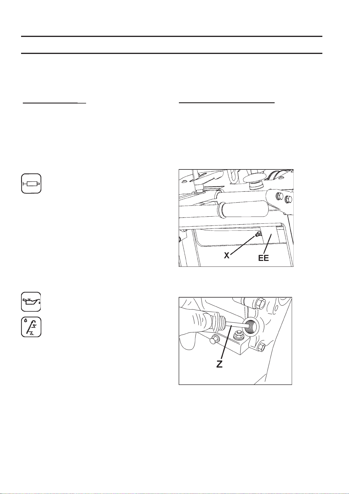
Depth Control Grease Fitting (X): A grease
tting allows lubrication of Blade Depth Control
(EE) screw. To access this grease tting:
• Raise the Diamond Blade (H) to maximum height.
Open Tool Compartment (BB), temporarily remove operation manual bag.
• Grease tting (X) is located near top of Blade Depth
Control (EE) Tube.
• Add Grease to the tting. Raise and lower the machine
a few times to circulate the grease through the tube.
• Replace Operation Manual Bag, close Tool Compartment (BB) door.
Engine Oil:
SERVICE EVERY 50 HOURS:
1. Replace engine oil and lter.
2. Clean engine/motor air ns.
3. Lubricate Depth Control Grease Fitting (X).
4. Check wheels for wear or damage.
5. Check blade drive belt tension.
Checking Engine Oil:
Check that engine oil level is correct.
Engine Oil Dipstick (Z) is located on front of
engine. Rell engine oil in dipstick hole. When
checking oil level, Engine Oil Dipstick (Z) should
not be screwed in.
Because engine often operates at an angle, check oil
level with engine horizontal. Check frequently to ensure
that oil level never falls below lower mark on dipstick.
10W30 oil is recommended.
See engine operation manual for more information.
26
MAINTENANCE & LUBRICATION
3
75 N-m
(55 ft-lbs)
FS 410 D
4
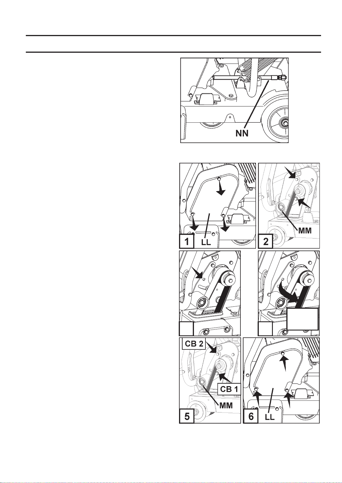
Changing Engine Oil:
• Turn machine Start Switch (DD) to OFF (0) position.
Let engine cool. Use Depth Control (EE) to tilt machine
slightly backwards.
• Reposition Oil Drain Hose (NN) to side of machine.
Set a suitable container, large enough to hold engine oil
capacity, beside machine to catch oil.
• Open end of Oil Drain Hose (NN), and let oil drain into
container. After oil is drained, replace Oil Drain Hose
(NN) end, tighten securely, return hose to original position.
• Fill engine with recomended quantity of oil - see engine
manual for details.
• Dispose of used oil in an environmentally safe manner.
Blade Shaft Drive Belt Tension: Drive Belt should be
re-tensioned after rst few hours of operation. Belt Drive
Idler (MM) holds tension on Drive Belt.
Tools Required:
• 13mm Wrench (Included with machine).
• 3/8” (9.53mm) Drive Torque Wrench (Not Included)
• 14mm Wrench (Not included with machine).
1. Use 13mm Wrench (U), to remove three (3) M8 bolts
that attach Belt Guard (LL). Remove Guard (LL).
2. Use the 13mm & 14mm wrenches to slightly loosen the
two (2) bolts that secure the Belt Drive Idler (MM) [bolts
indicated by (2) arrows].
3. Attach Torque Wrench to square hole in Belt Drive Idler
(MM).
4. Apply a torque to Drive Idler (MM) so that Drive Idler
(MM) is forced against the V-Belt. Torque to the value
shown in diagram 4.
5. Tighten center bolt (CB1) to hold Drive Idler (MM) in
position, then tighten remaining bolt (CB2).
6. Reinstall Belt Guard (LL). Use 13mm Wrench (U), to
tighten three (3) M8 bolts that attach Belt Guard (LL).
27

MAINTENANCE & LUBRICATION
Governor Speed
It is critical that Governor and throttle on all internal
combustion engines be adjusted properly. Engine speed
is preset at factory for proper sawing speed. It is NOT
normally necessary to change this setting. It should be
periodically veried after machine is placed into service.
To change the Governor setting, refer to the engine
manual.
WARNING!
Overspeeding Diamond Blade (H) can result in
blade breakage and/or personal injury to operator
and bystanders! To assure proper Governor
adjustment, determine correct blade shaft speed
(RPM) from the adjacent chart. Follow engine
manufacturer’s instruction procedure for Governor
and throttle setting.
Blade Shaft & Engine Speed
Model Blade Shaft
RPM
FS 410 D 2600 3600
Engine
RPM
28
TROUBLE SHOOTING GUIDE
Engine Will Not Start:
Cause Action
Electrical switches not in correct position. Check that BOTH Emergency Stop Switch (AA) and Engine
Fuel valve closed. Open the fuel valve.
Choke valve open. Close the choke with cold engine.
Fuel tank empty. Fill with fuel.
Contamination, or water ice in fuel system. Clean tank, fuel lines and carburetor. Fill tank with fresh fuel.
Buildup on spark plug electrodes. Check electrode gap and clean.
Engine has no power or runs unevenly. Air lter Clogged. Clean or replace the air lter.
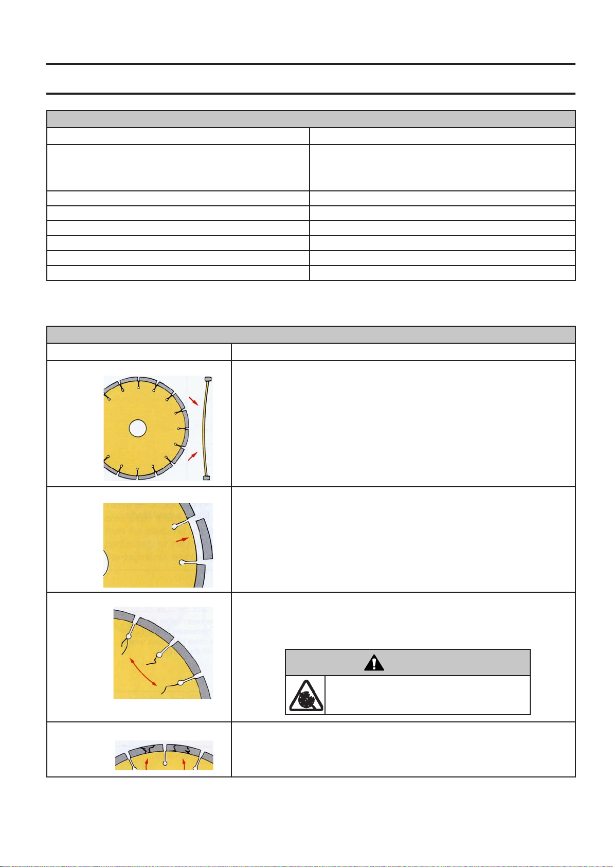
Diamond Blade Trouble Shooting:
Problem Cause & Action
Loss of Tension in Diamond Blade Blade being used on misaligned saw. Check for proper saw alignment.
Blade is excessively “hard” for material being cut, creating stress on steel blade
center. Check that blade is correct for material being cut.
Different diameter or undersize blade anges creates uneven pressure on blade
center. Use proper size ange on each side of blade. Never use worn or damaged anges.
Blade operated at improper speed (R.P.M.). Make certain blade shaft is turning at
the proper speed (R.P.M.) for blade size. Check R.P.M. using a tachometer.
Blade improperly mounted on arbor. Could become bent when anges are tightened.
Segment Loss Blade is too “hard” for material being cut. Use “softer” blade specication.
Overheated blade, detected as “blue” color on steel center. Check that water
supply is adequate and not blocked.
Saw is twisted while cutting. Saw only in a straight line.
Blade Bore is worn to an eccentric shape (ovalized). Replace worn blade and
worn spindle.
Segment knocked off during mounting our transport. Avoid rough handling of
diamond blade. Never transport the machine with the diamond blade mounted.
Cracked Blade Core Blade is too “hard” for material being cut. Use “softer” blade specication.
Overheated blade, detected as “blue” color on steel center. Check that water
supply is adequate and not blocked.
Saw is twisted while cutting. Saw only in a straight line.
Start Switch (DD) are in “ON” position. Emergency Stop
Switch (AA) should be pulled outward from cowl, and Engine
Start Switch (DD) turned to “1” (ON) position.
WARNING!
DO NOT use damaged diamond blades!
Death or injury could occur if machine is operated using damaged diamond blades!
Cracked Blade Segments Blade is too “hard” for material being cut. Use “softer” blade specication.
Blade operated at improper speed (R.P.M.). Make certain blade shaft is turning at
the proper speed (R.P.M.) for blade size. Check R.P.M. using a tachometer.
29

WIRING DIAGRAM
See
Engine
Operation
Manual.
30
 Loading...