


 Loading...
EchoLife HG520s Home Gateway
User Manual
HUAWEI TECHNOLOGIES CO., LTD.

EchoLife HG520s Home Gateway User Manual
Issue 03
Date 2007-03-31
No. 202013
Huawei Technologies Co., Ltd.
Address: |
Huawei Industrial Base |
|
Bantian, Longgang |
|
Shenzhen 518129 |
|
People's Republic of China |
Website: |
http://www.huawei.com |
Email: |
terminal@huawei.com |
Copyright © Huawei Technologies Co., Ltd. 2007. All rights reserved.
No part of this document may be reproduced or transmitted in any form or by any means without prior written consent of Huawei Technologies Co., Ltd.
Trademarks and Permissions
 and other Huawei trademarks are trademarks of Huawei Technologies Co., Ltd.
All other trademarks and trade names mentioned in this document are the property of their respective holders.
Notice
The information in this document is subject to change without notice. Every effort has been made in the preparation of this document to ensure accuracy of the contents, but all statements, information, and recommendations in this document do not constitute the warranty of any kind, express or implied.
This product has been designed to comply with the requirements on environmental protection. For the proper storage, use and disposal of this product, national laws and regulations must be observed.

Safety Precautions
General Requirements:
zBefore you install and use the device, read these safety precautions carefully and observe them during operation.
zDuring storage, transportation and operation of the device, keep the device dry.
zDuring storage, transportation and operation of the device, avoid collision and crash of the device.
zNever attempt to dismantle the device by yourself. In case of any fault, contact the appointed maintenance center for repair.
zWithout prior written consent, no organization or individual is permitted to make any change to the structure or safety design of the device. Huawei Technologies Co., Ltd. is not liable to any consequences or legal issues due to such changes.
zWhile using the device, observe all applicable laws, directives and regulations, and respect the legal rights of other people.
Environmental Requirements:
zPlace the device at a well-ventilated place. Do not dispose the device to direct sunlight.
zKeep the device clean and free of dusts.
zPlace the device on a stable platform.
zDo not place any object on top of the device. Otherwise, the device may be too hot during operation. It can even be deformed or damaged by the heavy load.
zKeep at least 10 cm between the device and the closest object for heat dissipation.
zDo not place the device on or near any object that can easily catch fire, such as something made of rubber.
zKeep the device far away from any heat source or bare fire, such as a candle or an electric heater.
zKeep the device far away from any household appliance with strong magnetic field or electromagnetic field, such as a microwave oven or a refrigerator.

Operating Requirements:
zDo no let a child operate the device without guidance.
zDo not let a child play with the device or any accessory. Swallowing the accessories may lead to peril.
zUse the accessories provided or authorized by the manufacturer only.
zThe power supply of the device shall meet the requirements of the input voltage of the device.
zBefore plugging or unplugging any cable, shut down the device and disconnect it from the power supply.
zWhile plugging or unplugging any cable, make sure that your hands are completely dry.
zDo not tread on, pull or over-bend any cable. Otherwise, the cable may be damaged, leading to malfunction of the device.
zDo not use an old or a damaged power cable.
zDuring lightning weather, stop using the device and disconnect it from the power supply. Unplug the power plug and the ADSL twisted pair, to avoid lightning strike.
zIf the device is not used for a long time, disconnect it from the power supply and unplug the power plug.
zIn any of the following cases, stop using the device, disconnect it from the power supply and unplug the power plug immediately: there is smoke emitted from the device, or there is some abnormal noise or smell. Contact the specified maintenance center for repair.
zAvoid any object (such as metal shavings) from entering the device from the heat dissipation intakes.
zDo not scratch or abrade the shell of the device. This may lead to malfunctions of the device. The shed painting material may also lead to skin allergy.
Cleaning Requirements:
zBefore cleaning the device, stop using it and disconnect it from the power supply.
zUse a piece of soft cloth to clean the device.
zKeep the power plug clean and dry. Using a dirty or wet power plug may lead to electric shock or other perils.
|
Table of Contents |
|
Chapter 1 Introduction ........................................................................ |
1 |
|
1.1 |
Functions and Features......................................................... |
1 |
1.2 |
Hardware Configuration ........................................................ |
1 |
|
1.2.1 Front Panel ................................................................. |
2 |
|
1.2.2 Rear Panel.................................................................. |
4 |
|
1.2.3 Splitter......................................................................... |
4 |
Chapter 2 Installation of the HG520s.................................................. |
6 |
|
2.1 |
Preparation............................................................................ |
6 |
2.2 |
Connecting the HG520s........................................................ |
6 |
2.3 |
Establishing Configuration Environment ............................... |
8 |
|
2.3.1 Parameter Configuration............................................. |
8 |
|
2.3.2 Steps........................................................................... |
9 |
2.4 |
Web Configuration Page ..................................................... |
10 |
Chapter 3 Service Configuration....................................................... |
11 |
|
3.1 |
Method ................................................................................ |
11 |
|
3.1.1 Protocol Model.......................................................... |
11 |
|
3.1.2 Steps......................................................................... |
12 |
3.2 |
Service Modes of the HG520s ............................................ |
12 |
3.3 |
Configuring the Bridge Mode .............................................. |
14 |
|
3.3.1 Preparation ............................................................... |
14 |
|
3.3.2 Steps......................................................................... |
15 |
3.4 |
Configuring the PPPoE Mode ............................................. |
17 |
|
3.4.1 Preparation ............................................................... |
17 |
|
3.4.2 Steps......................................................................... |
18 |
i
3.5 |
Configuring the PPPoA mode ............................................. |
20 |
3.6 |
Configuring the RFC2684B Mode ....................................... |
20 |
|
3.6.1 Preparation ............................................................... |
20 |
|
3.6.2 Steps......................................................................... |
21 |
3.7 |
Configuring the RFC2684 (IPoA) Mode .............................. |
23 |
3.8 |
Configuring the Wireless Mode ........................................... |
23 |
|
3.8.1 Preparation ............................................................... |
23 |
|
3.8.2 Steps......................................................................... |
24 |
Chapter 4 Advanced Configuration................................................... |
27 |
|
4.1 |
Preparation.......................................................................... |
27 |
4.2 |
Configuring the RIP ............................................................. |
27 |
4.3 |
Configuring the Security...................................................... |
28 |
4.4 |
Configuring the Filter........................................................... |
28 |
4.5 |
Configuring the QoS............................................................ |
31 |
4.6 |
Configuring the Port Mapping ............................................. |
34 |
4.7 |
Configuring the Timezone ................................................... |
35 |
4.8 |
Configuring the ACL............................................................ |
36 |
4.9 |
Configuring the UPnP.......................................................... |
37 |
Chapter 5 Other Settings .................................................................. |
38 |
|
5.1 |
Changing the IP Address of the LAN of the HG520s.......... |
38 |
5.2 |
Changing the Administrator Password of the HG520s ....... |
39 |
5.3 |
Restoring the Default Factory Settings ............................... |
39 |
5.4 |
Upgrading the Firmware...................................................... |
40 |
Chapter 6 Troubleshooting ............................................................... |
41 |
|
6.1 |
Quick Failure Location......................................................... |
41 |
ii
6.2 FAQs ................................................................................... |
42 |
||
Chapter 7 |
Technical Specifications .................................................. |
44 |
|
Chapter 8 |
Appendix .......................................................................... |
45 |
|
8.1 |
Default Factory Settings...................................................... |
45 |
|
|
8.1.1 Common Default Parameters ................................... |
45 |
|
|
8.1.2 Default PVC Parameters .......................................... |
45 |
|
8.2 |
Abbreviations....................................................................... |
46 |
|
iii
Chapter 1 Introduction
This chapter introduces functions and structure of the EchoLife HG520s Home Gateway (hereinafter referred to as the HG520s).
1.1 Functions and Features
The HG520s is a type of Asymmetric Digital Subscriber Line (ADSL) terminal. Data, video and audio are transmitted through the common telephone line at a higher rate by the HG520s.
The features of the HG520s are:
zHigh transmission rate: The maximum downstream rate is 24 Mbit/s; the maximum upstream rate is
1.2 Mbit/s.
zStrong network adaptability: The HG520s can be interconnected with multiple Digital Subscriber Line Access Multiplexer (DSLAMs).
zStrong maintainability: The HG520s provides multiple indicator status, which is convenient to locate failures.
zEasy operation: The HG520s has a simple operation for the configuration page.
1.2Hardware Configuration
This section introduces the appearance and the structure of the HG520s.
1
Note:
Figures of the front panel and the rear panel are only for your reference.
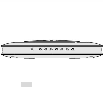
1.2.1 Front Panel
Figure 1-1 shows the front panel of the HG520s.
WLAN |
LAN4 LAN3 LAN2 LAN1 INTERNET ADSL POWER |
Figure 1-1 Front panel of the HG520s
Table 1-1 shows indicators in the front panel.
Table 1-1 Indicators in the front panel
Indicator |
Color |
Status |
Description |
|
|
|
On |
The connection is established in the |
|
|
|
WLAN interface. |
||
|
|
|
||
WLAN |
Green |
Blinking |
There are data being transmitted in |
|
the WLAN interface. |
||||
|
|
|
||
|
|
Off |
No connection is established in the |
|
|
|
WLAN interface. |
||
|
|
|
2
Indicator |
Color |
Status |
Description |
|
|
|
On |
The connection is established in the |
|
|
|
LAN interface. |
||
|
|
|
||
LAN1–4 |
Green |
Blinking |
There are data being transmitted in |
|
the LAN interface. |
||||
|
|
|
||
|
|
Off |
No connection is established in the |
|
|
|
LAN interface. |
||
|
|
|
||
|
|
|
The embedded PPPoE and PPPoA |
|
|
|
On |
dial-ups of the HG520s are |
|
|
|
successful, but there is no data |
||
|
|
|
||
|
|
|
transmission. |
|
INTERNET |
Green |
Blinking |
There are data are being transmitted |
|
|
|
in the INTERNET interface. |
||
|
|
|
||
|
|
|
The HG520s is in the bridge mode or |
|
|
|
Off |
the PPPoE/PPPoA connection is not |
|
|
|
|
established. |
|
|
|
On |
The DSL connection is established. |
|
|
|
|
|
|
|
|
|
There are data being transmitted in |
|
ADSL |
Green |
Blinking |
the DSL connection or the DSL |
|
|
connection is being activated. |
|||
|
|
|
The telephone line is not connected |
|
|
|
Off |
or the DSL connection is not |
|
|
|
|
established. |
|
POWER |
Green |
On |
The HG520s is powered on. |
|
|
|
|||
Off |
The HG520s is powered off. |
|||
|
|
Note:
PPPoE = Point-to-Point over Ethernet
PPPoA = Point-to-Point over ATM
LAN = Local Area Network
WLAN = Wireless Local Area Network
Note:
If the HG520s fails to activate, it tries again after an interval. The ADSL LINK indicator is off during the interval, lasting for about 1 minute.
3

1.2.2 Rear Panel
Figure 1-2 shows the rear panel of the HG520s.
|
|
|
|
|
|
|
|
|
|
|
|
|
|
|
|
|
|
|
|
|
|
|
|
|
|
|
|
|
|
|
|
|
|
|
|
|
|
|
|
|
|
|
|
|
|
|
|
|
|
|
|
|
|
|
|
|
|
|
|
|
|
|
|
|
|
|
|
|
|
|
|
|
|
|
|
|
|
|
|
|
|
|
|
|
|
|
|
|
|
|
|
|
|
|
|
|
|
|
|
|
|
|
|
|
|
|
|
|
|
|
|
|
|
|
|
|
|
|
|
|
|
|
|
|
|
|
|
|
|
|
|
|
|
|
|
|
|
|
|
RESET POWER ON/ OFF |
|
LAN1 |
|
LAN2 |
|
LAN3 |
|
LAN4 |
|
ADSL |
|||||||||||||||||
Figure 1-2 Rear panel of the HG520s
Table 1-2 shows interfaces and buttons in the rear panel.
Table 1-2 Interfaces and Buttons in the rear panel
Interface/Button
Antenna
RESET
POWER
ON/OFF
LAN 1–4
ADSL
Description Antenna for wireless Internet access.
To restart the HG520s, press the RESET button and release it within three seconds. To restore the default settings of the HG520s, press the RESET button and release it after three seconds. Once you use this function, all your custom settings will be lost. Therefore, please be careful when using it.
Connect to the power adapter. Power on/off the HG520s.
Ethernet interfaces.
To connect LAN network devices (such as a computer and a switch).
ADSL interface.
To connect the telephone jack or a splitter through a telephone line.
1.2.3 Splitter
The external splitter can efficiently reduce the signal disturbance on the telephone line. When voice and data are transmitted through the
4
same telephone line at the same time, you need an external splitter to separate the voice and data signals:
zLINE: Connecting to the phone jack on the wall.
zPHONE: Connecting to the telephone.
zMODEM: Connecting to the ADSL interface of the HG520s.
5
Chapter 2 Installation of the HG520s
This chapter introduces the installation when the HG520s is used for the first time.
2.1 Preparation
Connect your computer with the HG520s through the Ethernet interfaces. Before installing the HG520s, make sure that your computer is equipped with the network card
2.2 Connecting the HG520s
Figure 2-1 shows the connection of the HG520s.
6

USB
|
|
|
|
|
|
|
|
|
|
|
|
|
|
|
|
|
|
|
|
|
|
|
|
|
|
|
|
|
|
|
|
|
|
|
|
|
|
|
|
|
|
|
|
|
|
|
|
|
|
|
|
|
|
|
|
|
|
|
|
|
|
|
|
|
|
|
|
|
|
|
|
|
|
|
|
|
|
|
|
|
|
|
|
|
|
|
|
|
|
|
|
|
|
|
|
|
|
|
|
|
|
|
|
|
|
|
|
|
|
|
|
|
|
|
|
|
|
|
|
|
|
|
|
|
|
|
|
|
|
|
|
|
|
|
|
|
|
|
|
|
|
|
|
|
|
|
|
|
|
|
|
|
|
|
|
|
|
|
|
|
|
|
|
|
|
|
|
|
|
|
(1) |
Power adaptor |
(2) |
Switch |
(3) Computer |
||||||||||||||
(4) |
Set-Top Box |
(5) Modem port of splitter |
(6) Line interface |
|||||||||||||||
|
|
|
|
|
|
|
|
|
|
|
|
|
|
|
of splitter |
|||
(7) |
Phone interface of |
(8) |
Splitter |
(9) Phone |
||||||||||||||
splitter
(10) Phone Jack
Figure 2-1 Connection of the HG520s
Connect the HG520s as follows:
Caution:
Before connecting the HG520s, power off the HG520s and your computer.
(1)Connect the interfaces of the splitter with the corresponding equipment by using the telephone line.
7
zConnect the LINE interface of the splitter with the telephone jack on the wall.
zConnect the MODEM interface of the splitter with the ADSL interface of the HG520s.
zConnect the PHONE interface of the splitter with the
interface of the telephone line.
(2)Connect the Ethernet interface of the HG520s with the Ethernet interface of the computer by using Ethernet cable.
(3)Plug the output end of the provided power adapter into the power input interface of the HG520s; plug the other end into the power socket.
(4)Press the POWER button of the HG520s in the rear panel to power on the HG520s.
Check the power indicator in the front panel of the HG520s. If it is on, the HG520s is power on.
2.3Establishing Configuration Environment
You can configure the HG520s on the Web configuration page. This section describes the process to establish the configuration environment of the HG520s.
2.3.1 Parameter Configuration
Before establishing the configuration environment, set the following parameters.
Table 2-1 Parameters for the configuration environment
Name |
|
Description |
|
Administrator username and |
Default: |
||
z |
Username: admin |
||
password of the HG520s |
|||
z |
Password: admin |
||
|
|||
|
|
8 |
|
IP address and subnet mask |
Default: |
|
z |
IP address: 192.168.1.1 |
|
of the LAN of the HG520s |
z |
Subnet mask: 255.255.255.0 |
|
||
|
Set them to be in the same network |
|
|
segment as the IP address of the LAN of the |
|
IP address and subnet mask |
HG520s |
|
of the computer |
For example: |
|
|
z |
IP address: 192.168.1.100 |
|
z |
Subnet mask: 255.255.255.0 |
2.3.2 Steps
Follow the steps to establish the configuration environment.
Step |
|
|
To... |
|
Do... |
|
1 |
|
|
Connect the |
|
For details to connect the HG520s, refer to 2.2 |
|
|
|
HG520s |
|
"Connecting the HG520s." |
|
|
|
|
|
|
|
||
|
|
|
|
|
The process to unselect this function is described |
|
|
|
|
|
|
as follows (taking Internet Explorer 6.0 as an |
|
|
|
|
|
|
example): |
|
|
|
|
|
|
(1) Start the Internet Explorer. Select Tools > |
|
|
|
|
Make sure not |
|
Internet Options... to display the Internet |
|
2 |
|
|
to use the proxy |
|
Options dialog box. |
|
|
|
|
server. |
|
(2) Select the Connections |
tab. Click LAN |
|
|
|
|
|
Settings.... |
|
|
|
|
|
|
(3) Deselect Use a proxy server for your LAN |
|
|
|
|
|
|
(These settings will not apply to dial-up |
|
|
|
|
|
|
or VPN connections). |
|
|
|
|
|
|
(1) In the address bar of Internet Explorer, enter |
|
|
|
|
|
|
http://192.168.1.1 (the default IP address of |
|
|
|
|
Log in to the |
|
the HG520s). Then press Enter. The login |
|
3 |
|
|
Web |
|
window is displayed. |
|
|
|
configuration |
|
(2) Enter the username and the password of the |
||
|
|
|
|
|||
|
|
|
page |
|
administrator in the |
login window. |
|
|
|
|
|
When the password is authenticated, you |
|
|
|
|
|
|
can access the Web configuration page. |
|
|
|
|
|
|
|
|
|
|
|
|
9 |
|
|
Loading...