


 Loading...
OFFICEJET PRO X451 AND X551
SERIES PRINTERS
Repair Manual
HP OFFICEJET PRO X451 |
HP OFFICEJET PRO X551 |

HP Officejet Pro X451 and X551 Printer
Series
Repair Manual
Copyright and License
© 2013 Copyright Hewlett-Packard
Development Company, L.P.
Reproduction, adaptation, or translation without prior written permission is prohibited, except as allowed under the copyright laws.
The information contained herein is subject to change without notice.
The only warranties for HP products and services are set forth in the express warranty statements accompanying such products and services. Nothing herein should be construed as constituting an additional warranty. HP shall not be liable for technical or editorial errors or omissions contained herein.
CV037-90002
Edition 2, 12/2013
Trademark Credits
Adobe®, Acrobat®, and PostScript® are trademarks of Adobe Systems Incorporated.
Intel® Core™ is a trademark of Intel Corporation in the U.S. and other countries.
Java™ is a US trademark of Sun
Microsystems, Inc.
Microsoft®, Windows®, Windows® XP, and Windows Vista® are U.S. registered trademarks of Microsoft Corporation.
UNIX® is a registered trademark of The Open Group.
ENERGY STAR and the ENERGY STAR mark are registered U.S. marks.

Conventions used in this guide

 TIP: Tips provide helpful hints or shortcuts.
 NOTE: Notes provide important information to explain a concept or to complete a task.
CAUTION: Cautions indicate procedures that you should follow to avoid losing data or damaging the product.
WARNING! Warnings alert you to specific procedures that you should follow to avoid personal injury, catastrophic loss of data, or extensive damage to the product.
ENWW |
iii |

Table of contents
1 Removal and replacement ................................................................................................ |
1 |
Removal and replacement strategy ............................................................................................. |
2 |
Electrostatic discharge ............................................................................................... |
2 |
Required tools ........................................................................................................... |
3 |
OfficeJet Pro X special tools kit .................................................................................... |
3 |
Advanced Cleaning Kit .............................................................................................. |
5 |
Service approach ..................................................................................................................... |
5 |
Before performing service .......................................................................................... |
5 |
After performing service ............................................................................................. |
5 |
Post-service test ......................................................................................................... |
6 |
Print-quality test .......................................................................................... |
6 |
Removal and replacement procedures ........................................................................................ |
7 |
Customer replaceable parts ........................................................................................ |
7 |
Tray 2 ....................................................................................................... |
7 |
Ink cartridges ............................................................................................. |
8 |
Duplex module ......................................................................................... |
12 |
Output bin ............................................................................................... |
13 |
Output bin flap ........................................................................................ |
13 |
Menu access .......................................................................................................... |
14 |
Access the Engineering menu .................................................................... |
14 |
Access the Support Menu .......................................................................... |
15 |
Place the product into MFG (manufacturing) mode ....................................... |
15 |
Place the product into Audit mode .............................................................. |
15 |
Perform tap tests and interpret results ......................................................................... |
17 |
10 tap test results (OOBE States) ................................................................ |
17 |
12 tap test results (REDI sensor values) ........................................................ |
19 |
61 tap results (Align & color calibrations) .................................................... |
21 |
909 tap test results (BDD status) ................................................................. |
22 |
Covers ................................................................................................................... |
23 |
Rear cover ............................................................................................... |
23 |
Left door ................................................................................................. |
24 |
Left rear cover .......................................................................................... |
27 |
ENWW |
v |
Left front cover ......................................................................................... |
28 |
Top cover ................................................................................................ |
29 |
Front cover .............................................................................................. |
34 |
Right cover .............................................................................................. |
35 |
Main assemblies ..................................................................................................... |
36 |
Aerosol fan assembly ................................................................................ |
36 |
Separator/pick assembly .......................................................................... |
43 |
Duplex drive module ................................................................................. |
48 |
Control panel (X451 models only) .............................................................. |
50 |
Control panel (X551 models only) .............................................................. |
51 |
Power supply ........................................................................................... |
53 |
Backscatter drop detect (BDD) assembly ...................................................... |
55 |
Service sled assembly ............................................................................... |
57 |
Right cross brace ...................................................................................... |
62 |
Plate console left ...................................................................................... |
65 |
Plate console right .................................................................................... |
66 |
Printbar ................................................................................................... |
67 |
Printbar calibration procedure ................................................................... |
75 |
Printbar FFC replacement .......................................................................... |
77 |
Platen ..................................................................................................... |
78 |
Drying path gear assembly ........................................................................ |
82 |
Printbar lift mechanism assembly ................................................................ |
83 |
Tray lift transmission assembly ................................................................... |
85 |
Output drive kit ........................................................................................ |
87 |
Output drive gears ................................................................................... |
90 |
Output drive shaft 6 .................................................................................. |
90 |
Output drive shaft 5 .................................................................................. |
92 |
Output drive shaft 4 .................................................................................. |
94 |
Drive shaft 3 ............................................................................................ |
95 |
Inner top frame ........................................................................................ |
98 |
Top paper guide .................................................................................... |
101 |
Top left paper guide assembly ................................................................. |
104 |
Center left paper guide assembly ............................................................. |
106 |
Paper REDI sensors in the center left paper guide assembly ......................... |
108 |
Service sled transmission ......................................................................... |
109 |
Printed circuit-board assemblies (PCAs) .................................................................... |
110 |
PCA safety shield ................................................................................... |
110 |
Sensor carriage PCA and encoder strip .................................................... |
111 |
Power button PCA .................................................................................. |
115 |
Duplex module sensor PCA ..................................................................... |
116 |
Temperature sensor ................................................................................ |
117 |
vi |
ENWW |
REDI distribution PCA ............................................................................. |
118 |
Feed motor encoder sensor PCA .............................................................. |
119 |
Eject flap opto PCA ................................................................................ |
122 |
Printzone distribution PCA ....................................................................... |
122 |
Media presence sensor PCA/flag ............................................................ |
125 |
Main PCA ............................................................................................. |
126 |
Main PCA calibration procedure .............................................................. |
131 |
Tray 3 interconnect PCA ......................................................................... |
134 |
Pick encoder distribution PCA .................................................................. |
135 |
Wireless PCA ........................................................................................ |
136 |
2 Parts and diagrams ...................................................................................................... |
137 |
Order parts by authorized service providers ............................................................................ |
138 |
Order replacement parts ........................................................................................ |
138 |
Related documentation and software ....................................................................... |
138 |
Supplies part numbers ........................................................................................... |
138 |
Customer self-repair parts ....................................................................................... |
139 |
How to use the parts lists and diagrams .................................................................................. |
141 |
Assembly locations ............................................................................................................... |
142 |
Front view (X451 Series) ........................................................................................ |
142 |
Front view (X551 Series) ........................................................................................ |
143 |
Back view ............................................................................................................ |
144 |
Covers, panels, and doors .................................................................................................... |
146 |
Internal assemblies ............................................................................................................... |
148 |
Alphabetical parts list ........................................................................................................... |
158 |
Numerical parts list .............................................................................................................. |
163 |
Index ............................................................................................................................... |
169 |
ENWW |
vii |

List of figures
Figure 1-1 OfficeJet Pro X special tools–ink supply door switch ................................................................... |
3 |
Figure 1-2 OfficeJet Pro X special tools–printbar lift knob ........................................................................... |
4 |
Figure 1-3 OfficeJet Pro X special tools–service sled advance tool ............................................................... |
4 |
Figure 1-4 OfficeJet Pro X special tools–printbar dolly ............................................................................... |
4 |
Figure 1-5 Remove Tray 2 (1 of 2) .......................................................................................................... |
7 |
Figure 1-6 Remove Tray 2 (2 of 2) .......................................................................................................... |
8 |
Figure 1-7 Replace the ink cartridges (1 of 7) ........................................................................................... |
8 |
Figure 1-8 Replace the ink cartridges (2 of 7) ........................................................................................... |
9 |
Figure 1-9 Replace the ink cartridges (3 of 7) ........................................................................................... |
9 |
Figure 1-10 Replace the ink cartridges (4 of 7) ....................................................................................... |
10 |
Figure 1-11 Replace the ink cartridges (5 of 7) ....................................................................................... |
10 |
Figure 1-12 Replace the ink cartridges (6 of 7) ....................................................................................... |
11 |
Figure 1-13 Replace the ink cartridges (7 of 7) ....................................................................................... |
11 |
Figure 1-14 Remove the duplex module (1 of 2) ..................................................................................... |
12 |
Figure 1-15 Remove the duplex module (2 of 2) ..................................................................................... |
12 |
Figure 1-16 Remove the output bin ........................................................................................................ |
13 |
Figure 1-17 Remove the output bin flap ................................................................................................. |
13 |
Figure 1-18 X451 control panel button locations .................................................................................... |
14 |
Figure 1-19 X551 control panel button locations .................................................................................... |
14 |
Figure 1-20 10 tap test results .............................................................................................................. |
18 |
Figure 1-21 12 tap test report .............................................................................................................. |
20 |
Figure 1-22 61 tap test results .............................................................................................................. |
21 |
Figure 1-23 909 tap test results ............................................................................................................ |
22 |
Figure 1-24 Remove the rear cover (1 of 2) ............................................................................................ |
23 |
Figure 1-25 Remove the rear cover (2 of 2) ............................................................................................ |
23 |
Figure 1-26 Remove left door (1 of 6) .................................................................................................... |
24 |
Figure 1-27 Remove the left door (2 of 6) .............................................................................................. |
24 |
Figure 1-28 Remove the left door (3 of 6) .............................................................................................. |
25 |
Figure 1-29 Remove the left door (4 of 6) .............................................................................................. |
26 |
Figure 1-30 Remove the left door (5 of 6) .............................................................................................. |
26 |
Figure 1-31 Remove the left door (6 of 6) .............................................................................................. |
27 |
Figure 1-32 Remove the left rear cover (1 of 2) ....................................................................................... |
27 |
ENWW |
ix |
Figure 1-33 Remove the left rear cover (2 of 2) ....................................................................................... |
28 |
Figure 1-34 Remove the left front cover (1 of 2) ...................................................................................... |
28 |
Figure 1-35 Remove the left front cover (2 of 2) ...................................................................................... |
29 |
Figure 1-36 Remove the top cover (1 of 8) ............................................................................................. |
30 |
Figure 1-37 Remove the top cover (2 of 8) ............................................................................................. |
30 |
Figure 1-38 Remove the top cover (3 of 8) – X451 models ....................................................................... |
31 |
Figure 1-39 Remove the top cover (4 of 8) – X551 models ....................................................................... |
31 |
Figure 1-40 Remove the top cover (5 of 8) ............................................................................................. |
32 |
Figure 1-41 Remove the top cover (6 of 8) ............................................................................................. |
32 |
Figure 1-42 Remove the top cover (7 of 8) ............................................................................................. |
33 |
Figure 1-43 Remove the top cover (8 of 8) ............................................................................................. |
33 |
Figure 1-44 Remove the front cover (1 of 2) ........................................................................................... |
34 |
Figure 1-45 Remove the front cover (2 of 2) ........................................................................................... |
34 |
Figure 1-46 Remove the right cover (1 of 2) ........................................................................................... |
35 |
Figure 1-47 Remove the right cover (2 of 2) ........................................................................................... |
35 |
Figure 1-48 Remove the aerosol fan (1 of 12) ........................................................................................ |
36 |
Figure 1-49 Remove the aerosol fan (2 of 12) ........................................................................................ |
37 |
Figure 1-50 Remove the aerosol fan (3 of 12) ........................................................................................ |
37 |
Figure 1-51 Remove the aerosol fan (4 of 12) ........................................................................................ |
38 |
Figure 1-52 Remove the aerosol fan (5 of 12) ........................................................................................ |
38 |
Figure 1-53 Remove the aerosol fan (6 of 12) ........................................................................................ |
39 |
Figure 1-54 Remove the aerosol fan (7 of 12) ........................................................................................ |
39 |
Figure 1-55 Remove the aerosol fan (8 of 12) ........................................................................................ |
40 |
Figure 1-56 Remove the aerosol fan (9 of 12) ........................................................................................ |
40 |
Figure 1-57 Remove the aerosol fan (10 of 12) ...................................................................................... |
41 |
Figure 1-58 Remove the aerosol fan (11 of 12) ...................................................................................... |
41 |
Figure 1-59 Remove the aerosol fan (12 of 12) ...................................................................................... |
42 |
Figure 1-60 Remove the separator/pick assembly (1 of 4) ....................................................................... |
43 |
Figure 1-61 Remove the separator/pick assembly (2 of 4) ....................................................................... |
44 |
Figure 1-62 Remove the separator/pick assembly (3 of 4) ....................................................................... |
45 |
Figure 1-63 Remove the separator/pick assembly (4 of 4) ....................................................................... |
45 |
Figure 1-64 Reinstall the separator/pick assembly (1 of 5) ....................................................................... |
46 |
Figure 1-65 Reinstall the separator/pick assembly (2 of 5) ....................................................................... |
46 |
Figure 1-66 Reinstall the separator/pick assembly (3 of 5) ....................................................................... |
47 |
Figure 1-67 Reinstall the separator/pick assembly (4 of 5) ....................................................................... |
47 |
Figure 1-68 Reinstall the separator/pick assembly (5 of 5) ....................................................................... |
48 |
Figure 1-69 Remove the duplex drive module (1 of 2) ............................................................................. |
49 |
Figure 1-70 Remove the duplex drive module (2 of 2) ............................................................................. |
49 |
Figure 1-71 Remove the control panel (1 of 2) ........................................................................................ |
50 |
Figure 1-72 Remove the control panel (2 of 2) ........................................................................................ |
50 |
Figure 1-73 Remove the touchscreen control panel (1 of 4) ...................................................................... |
51 |
x |
ENWW |
Figure 1-74 Remove the touchscreen control panel (2 of 4) ...................................................................... |
51 |
Figure 1-75 Remove the touchscreen control panel (3 of 4) ...................................................................... |
52 |
Figure 1-76 Remove the touchscreen control panel (4 of 4) ...................................................................... |
52 |
Figure 1-77 Remove the power supply (1 of 3) ....................................................................................... |
53 |
Figure 1-78 Remove the power supply (2 of 3) ....................................................................................... |
54 |
Figure 1-79 Remove the power supply (3 of 3) ....................................................................................... |
54 |
Figure 1-80 Remove the backscatter drop detect assembly (1 of 2) ........................................................... |
55 |
Figure 1-81 Remove the backscatter drop detect assembly (2 of 2) ........................................................... |
56 |
Figure 1-82 Remove the service sled assembly (1 of 6) ............................................................................ |
57 |
Figure 1-83 Remove the service sled assembly (2 of 6) ............................................................................ |
58 |
Figure 1-84 Remove the service sled assembly (3 of 6) ............................................................................ |
58 |
Figure 1-85 Remove the service sled assembly (4 of 6) ............................................................................ |
59 |
Figure 1-86 Remove the service sled assembly (5 of 6) ............................................................................ |
59 |
Figure 1-87 Remove the service sled assembly (6 of 6) ............................................................................ |
60 |
Figure 1-88 Remove the web advance rack assembly (1 of 2) .................................................................. |
61 |
Figure 1-89 Remove the web advance rack assembly (2 of 2) .................................................................. |
61 |
Figure 1-90 Remove the right cross brace (1 of 4) ................................................................................... |
62 |
Figure 1-91 Remove the right cross brace (2 of 4) ................................................................................... |
63 |
Figure 1-92 Remove the right cross brace (3 of 4) ................................................................................... |
63 |
Figure 1-93 Remove the right cross brace (4 of 4) ................................................................................... |
64 |
Figure 1-94 Remove the plate console left .............................................................................................. |
65 |
Figure 1-95 Remove the plate console right (1 of 2) ................................................................................ |
66 |
Figure 1-96 Remove the plate console right (2 of 2) ................................................................................ |
67 |
Figure 1-97 Remove the printbar (1 of 12) ............................................................................................. |
68 |
Figure 1-98 Remove the printbar (2 of 12) ............................................................................................. |
68 |
Figure 1-99 Remove the printbar (3 of 12) ............................................................................................. |
69 |
Figure 1-100 Remove the printbar (4 of 12) ........................................................................................... |
69 |
Figure 1-101 Remove the printbar (5 of 12) ........................................................................................... |
70 |
Figure 1-102 Remove the printbar (6 of 12) ........................................................................................... |
71 |
Figure 1-103 Remove the printbar (7 of 12) ........................................................................................... |
71 |
Figure 1-104 Remove the printbar (8 of 12) ........................................................................................... |
72 |
Figure 1-105 Remove the printbar (9 of 12) ........................................................................................... |
72 |
Figure 1-106 Remove the printbar (10 of 12) ......................................................................................... |
73 |
Figure 1-107 Remove the printbar (11 of 12) ......................................................................................... |
73 |
Figure 1-108 Remove the printbar (12 of 12) ......................................................................................... |
74 |
Figure 1-109 Replace the printbar control FFCs (1 of 2) .......................................................................... |
77 |
Figure 1-110 Replace the printbar control FFCs (2 of 2) .......................................................................... |
77 |
Figure 1-111 Remove the platen (1 of 7) ............................................................................................... |
78 |
Figure 1-112 Remove the platen (2 of 7) ............................................................................................... |
79 |
Figure 1-113 Remove the platen (3 of 7) ............................................................................................... |
79 |
Figure 1-114 Remove the platen (4 of 7) ............................................................................................... |
80 |
ENWW |
xi |
Figure 1-115 Remove the platen (5 of 7) ............................................................................................... |
80 |
Figure 1-116 Remove the platen (6 of 7) ............................................................................................... |
81 |
Figure 1-117 Remove the platen (7 of 7) ............................................................................................... |
82 |
Figure 1-118 Remove the drying path gear assembly .............................................................................. |
82 |
Figure 1-119 Remove the printbar lift motor (1 of 2) ................................................................................ |
83 |
Figure 1-120 Remove the printbar lift motor (2 of 2) ................................................................................ |
84 |
Figure 1-121 Remove the tray lift transmission assembly (1 of 2) ............................................................... |
85 |
Figure 1-122 Remove the tray lift transmission assembly (2 of 2) ............................................................... |
86 |
Figure 1-123 Remove the flap actuator solenoid ..................................................................................... |
87 |
Figure 1-124 Remove the rack-eject lifter flap (1 of 3) ............................................................................. |
88 |
Figure 1-125 Remove the rack-eject lifter flap (2 of 3) ............................................................................. |
88 |
Figure 1-126 Remove the rack-eject lifter flap (3 of 3) ............................................................................. |
89 |
Figure 1-127 Remove the eject drive gear module .................................................................................. |
89 |
Figure 1-128 Remove the output drive gears .......................................................................................... |
90 |
Figure 1-129 Remove the output drive shaft 6 (1 of 3) ............................................................................. |
91 |
Figure 1-130 Remove the output drive shaft 6 (2 of 3) ............................................................................. |
91 |
Figure 1-131 Remove the output drive shaft 6 (3 of 3) ............................................................................. |
92 |
Figure 1-132 Remove the output drive shaft 5 (1 of 2) ............................................................................. |
93 |
Figure 1-133 Remove the output drive shaft 5 (2 of 2) ............................................................................. |
93 |
Figure 1-134 Remove the output drive shaft 4 (1 of 2) ............................................................................. |
94 |
Figure 1-135 Remove the output drive shaft 4 (2 of 2) ............................................................................. |
95 |
Figure 1-136 Remove drive shaft 3 (1 of 4) ............................................................................................ |
96 |
Figure 1-137 Remove drive shaft 3 (2 of 4) ............................................................................................ |
96 |
Figure 1-138 Remove drive shaft 3 (3 of 4) ............................................................................................ |
97 |
Figure 1-139 Remove drive shaft 3 (4 of 4) ............................................................................................ |
97 |
Figure 1-140 Remove the inner top frame (1 of 5) .................................................................................. |
98 |
Figure 1-141 Remove the inner top frame (2 of 5) .................................................................................. |
99 |
Figure 1-142 Remove the inner top frame (3 of 5) .................................................................................. |
99 |
Figure 1-143 Remove the inner top frame (4 of 5) ................................................................................ |
100 |
Figure 1-144 Remove the inner top frame (5 of 5) ................................................................................ |
100 |
Figure 1-145 Remove the top paper guide (1 of 6) ............................................................................... |
101 |
Figure 1-146 Remove the top paper guide (2 of 6) ............................................................................... |
101 |
Figure 1-147 Remove the top paper guide (3 of 6) ............................................................................... |
102 |
Figure 1-148 Remove the top paper guide (4 of 6) ............................................................................... |
102 |
Figure 1-149 Remove the top paper guide (5 of 6) ............................................................................... |
103 |
Figure 1-150 Remove the top paper guide (6 of 6) ............................................................................... |
103 |
Figure 1-151 Remove the top left paper guide (1 of 4) .......................................................................... |
104 |
Figure 1-152 Remove the top left paper guide (2 of 4) .......................................................................... |
104 |
Figure 1-153 Remove the top left paper guide (3 of 4) .......................................................................... |
105 |
Figure 1-154 Remove the top left paper guide (4 of 4) .......................................................................... |
105 |
Figure 1-155 Remove the center left paper guide (1 of 4) ...................................................................... |
106 |
xii |
ENWW |
Figure 1-156 Remove the center left paper guide (2 of 4) ...................................................................... |
106 |
Figure 1-157 Remove the center left paper guide (3 of 4) ...................................................................... |
107 |
Figure 1-158 Remove the center left paper guide (4 of 4) ...................................................................... |
107 |
Figure 1-159 Remove the paper REDI sensors ....................................................................................... |
108 |
Figure 1-160 Correctly positioned service sled transmission ................................................................... |
109 |
Figure 1-161 Incorrectly positioned service sled transmission ................................................................. |
109 |
Figure 1-162 Remove the PCA safety shield (1 of 2) .............................................................................. |
110 |
Figure 1-163 Remove the PCA safety shield (2 of 2) .............................................................................. |
110 |
Figure 1-164 Remove the sensor carriage PCA and encoder strip (1 of 8) ............................................... |
111 |
Figure 1-165 Remove the sensor carriage PCA and encoder strip (2 of 8) ............................................... |
111 |
Figure 1-166 Remove the sensor carriage PCA and encoder strip (3 of 8) ............................................... |
112 |
Figure 1-167 Remove the sensor carriage PCA and encoder strip (4 of 8) ............................................... |
112 |
Figure 1-168 Remove the sensor carriage PCA and encoder strip (5 of 8) ............................................... |
113 |
Figure 1-169 Remove the sensor carriage PCA and encoder strip (6 of 8) ............................................... |
113 |
Figure 1-170 Remove the sensor carriage PCA and encoder strip (7 of 8) ............................................... |
114 |
Figure 1-171 Remove the sensor carriage PCA and encoder strip (8 of 8) ............................................... |
114 |
Figure 1-172 Remove the power button PCA (1 of 2) ............................................................................ |
115 |
Figure 1-173 Remove the power button PCA (2 of 2) ............................................................................ |
115 |
Figure 1-174 Remove the duplex module sensor PCA (1 of 2) ................................................................ |
116 |
Figure 1-175 Remove the duplex module sensor PCA (2 of 2) ................................................................ |
116 |
Figure 1-176 Remove the temperature sensor (1 of 2) ........................................................................... |
117 |
Figure 1-177 Remove the temperature sensor (2 of 2) ........................................................................... |
117 |
Figure 1-178 Remove the REDI distribution PCA (1 of 3) ........................................................................ |
118 |
Figure 1-179 Remove the REDI distribution PCA (2 of 3) ........................................................................ |
118 |
Figure 1-180 Remove the REDI distribution PCA (3 of 3) ........................................................................ |
119 |
Figure 1-181 Remove the feed motor encoder sensor PCA (1 of 4) ......................................................... |
119 |
Figure 1-182 Remove the feed motor encoder sensor PCA (2 of 4) ......................................................... |
120 |
Figure 1-183 Remove the feed motor encoder sensor PCA (3 of 4) ......................................................... |
120 |
Figure 1-184 Remove the feed motor encoder sensor PCA (4 of 4) ......................................................... |
121 |
Figure 1-185 Remove the eject flap opto PCA ...................................................................................... |
122 |
Figure 1-186 Remove the printzone distribution PCA (1 of 3) ................................................................. |
123 |
Figure 1-187 Remove the printzone distribution PCA (2 of 3) ................................................................. |
123 |
Figure 1-188 Remove the printzone distribution PCA (3 of 3) ................................................................. |
124 |
Figure 1-189 Remove the media presence sensor PCA/flag (1 of 2) ....................................................... |
125 |
Figure 1-190 Remove the media presence sensor PCA/flag (2 of 2) ....................................................... |
125 |
Figure 1-191 Remove the main PCA (1 of 8) ........................................................................................ |
127 |
Figure 1-192 Remove the main PCA (2 of 8) ........................................................................................ |
127 |
Figure 1-193 Remove the main PCA (3 of 8) ........................................................................................ |
128 |
Figure 1-194 Remove the main PCA (4 of 8) ........................................................................................ |
128 |
Figure 1-195 Remove the main PCA (5 of 8) ........................................................................................ |
129 |
Figure 1-196 Remove the main PCA (6 of 8) ........................................................................................ |
129 |
ENWW |
xiii |
Figure 1-197 Remove the main PCA (7 of 8) ........................................................................................ |
130 |
Figure 1-198 Remove the main PCA (8 of 8) ........................................................................................ |
130 |
Figure 1-199 Remove the Tray 3 interconnect PCA (1 of 2) .................................................................... |
134 |
Figure 1-200 Remove the Tray 3 interconnect PCA (2 of 2) .................................................................... |
134 |
Figure 1-201 Remove the pick encoder distribution PCA (1 of 2) ............................................................ |
135 |
Figure 1-202 Remove the pick encoder distribution PCA (2 of 2) ............................................................ |
135 |
Figure 1-203 Remove the wireless PCA. .............................................................................................. |
136 |
Figure 2-1 Front view (X451 Series) .................................................................................................... |
142 |
Figure 2-2 Front view (X551 Series) .................................................................................................... |
143 |
Figure 2-3 Back view ........................................................................................................................ |
144 |
Figure 2-4 Covers, panels, and doors ................................................................................................. |
146 |
Figure 2-5 Internal assemblies (1 of 3) ................................................................................................. |
148 |
Figure 2-6 Internal assemblies (2 of 3) ................................................................................................. |
150 |
Figure 2-7 Internal assemblies (3 of 3) ................................................................................................. |
152 |
Figure 2-8 PCA locations (1 of 2) ........................................................................................................ |
154 |
Figure 2-9 PCA locations (2 of 2) ........................................................................................................ |
156 |
xiv |
ENWW |

1 Removal and replacement
●Removal and replacement strategy
●Service approach
●Removal and replacement procedures
ENWW |
1 |
Removal and replacement strategy
WARNING! Turn the product off, wait 5 seconds, and then remove the power cord before attempting to service the product. If this warning is not followed, severe injury can result, in addition to damage to the product. The power must be on for certain functional checks during problem solving. However, the power supply should be disconnected during parts removal.
The sheet-metal parts can have sharp edges. Be careful when handling sheet-metal parts.
CAUTION: Many repair operations will require you to flatten or straighten flex cables. However, where possible, try to avoid doing so. You must make sure that all FFCs are fully seated in their connectors. Failure to fully seat an FFC into a connector can cause a short circuit in a PCA.


 NOTE: To install a self-tapping screw, first turn it counterclockwise to align it with the existing thread pattern, and then carefully turn it clockwise to tighten. Do not overtighten. If a self-tapping screw-hole becomes stripped, repair the screw-hole or replace the affected assembly.
Throughout this chapter, the reinstallation process should follow the reverse order of the removal process documented. Where necessary, the tasks include reinstallation tips to aid in the installation of replacement parts.
Electrostatic discharge
|
CAUTION: |
|
Some parts are sensitive to electrostatic discharge (ESD). Look for the ESD reminder |
|
|||
|
|||
|
|
|
|
when removing product parts. Always perform service work at an ESD-protected workstation or mat. If an ESD workstation or mat is not available, ground yourself by touching the sheet-metal chassis before touching an ESD-sensitive part.
Protect the ESD-sensitive parts by placing them in ESD pouches when they are out of the product.
2 |
Chapter 1 Removal and replacement |
ENWW |
Required tools
●#T10 TORX driver with a magnetic tip and a 152 mm (6 in) shaft length
●#T10 TORX driver with a magnetic tip and a 25 mm (1 in) shaft length
●Small flat-blade screwdriver
●Needle-nose pliers
●Tweezers
●ESD mat (if one is available) or ESD strap
●Penlight
●1/4” (6.4mm) nut driver (for use with the OfficeJet Pro X special tools kit)
CAUTION: While the use of a motorized screwdriver is recommended, the screwdriver must have a torque limiter, and it must be set to a low torque.
OfficeJet Pro X special tools kit
The OfficeJet Pro X special tools kit (part number CN598-67056) is required for replacing the service sled and printbar assemblies.
The OfficeJet Pro X special tools kit contains the following parts:
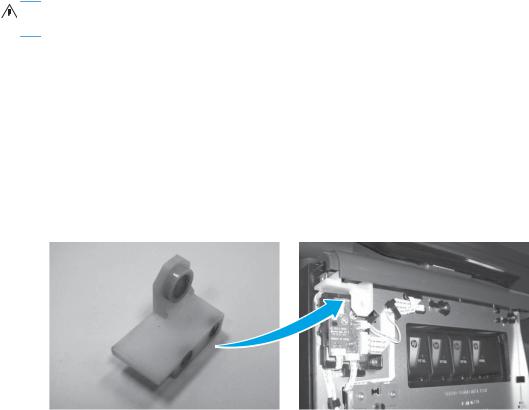
●Ink supply door switch–used to tell the printer that the supply door is closed when the front cover is removed.
Figure 1-1 OfficeJet Pro X special tools–ink supply door switch
ENWW |
Removal and replacement strategy |
3 |

●Printbar lift knob–used for lifting and holding the printbar.
 NOTE: Use a ¼” nut driver (6.4mm) to raise the printbar.
Figure 1-2 OfficeJet Pro X special tools–printbar lift knob
●Service sled advance tool–used to remove and reinstall the service sled.
 NOTE: Use a ¼” nut driver (6.4mm) to remove or install the service sled
Figure 1-3 OfficeJet Pro X special tools–service sled advance tool
●Printbar dolly–used to support the printbar during removal and installation.
Figure 1-4 OfficeJet Pro X special tools–printbar dolly
4 |
Chapter 1 Removal and replacement |
ENWW |

Advanced Cleaning Kit
The Advanced Cleaning Kit (part number CN459-67006) is used for resolving shim whiskers print quality issues.
The Advanced Cleaning Kit contains the following items:
●Sheet cleaner - full mid
●Shim whisker kit Instructions
●Corrugated box
●Corrugated insert
Service approach


 IMPORTANT: Ensure the product has the latest firmware installed for the initial installation of the product. Certain repairs to this product also require updated firmware, as noted in this document. Download firmware for this product at www.hp.com.
CAUTION: When working on the product, do not pick up the unit by the output tray, which will likely detach under the weight of the product.
Before performing service
●Remove all paper from the product.
●Turn off the power using the power button.
●Unplug the power cable and interface cable or cables.
●Remove the output bin.
●Place the product on an ESD workstation or mat, or use an ESD strap (if one is available). If an ESD workstation, mat, or strap is not available, ground yourself by touching the sheet-metal chassis before touching an ESD-sensitive part.
●Remove the Tray 2 cassette.
●Remove the duplex module, which is located inside the left door.


 NOTE: When removing the duplex module, avoid making direct contact with the black cylinder to prevent ink smear on skin or clothes. Keep the duplex module level to avoid spilling any maintenance ink.
After performing service
●Plug in the power cable.
●Reinstall the output bin.
●Reinstall the ink cartridges (if they were removed prior to performing service).
ENWW |
Service approach |
5 |
●Reinstall the Tray 2 cassette.
●Reinstall the duplex module.
●Load paper in the product.
Post-service test
Perform the following test to verify that the repair or replacement was successful.
Print-quality test
1.Verify that the necessary reassembly steps have been completed.
2.Make sure that the tray contains clean, unmarked paper.
3.Attach the power cord and interface cable or interface cables, and then turn on the product.
4.Verify that the expected startup sounds occur.
5.Print a configuration page, and verify that the expected printing sounds occur.
6.Print a print-quality page, and then verify that there are no lines, streaks, banding, or other print quality defects.
7.Send a print job from the host computer, and then verify that the output meets expectations.
8.Clean the outside of the product with a damp cloth.
6 |
Chapter 1 Removal and replacement |
ENWW |
Removal and replacement procedures


 NOTE: Due to time constraints in producing this manual, the product might look slightly different than what is depicted in the photographs in this section. Most changes will be cosmetic in nature and should not affect the repair procedures.
Customer replaceable parts
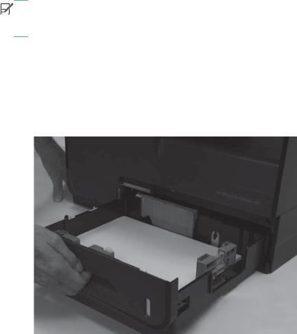
Tray 2
1.Pull out the tray.
Figure 1-5 Remove Tray 2 (1 of 2)
ENWW |
Removal and replacement procedures |
7 |
2.Press the latch in left-rear corner of the tray.
Figure 1-6 Remove Tray 2 (2 of 2)
3.Remove the tray from the product.
Ink cartridges
The product uses four colors and has a different ink cartridge for each color: yellow (Y), cyan (C), magenta (M), and black (K).
1.Open the ink cartridge access door.
Figure 1-7 Replace the ink cartridges (1 of 7)
8 |
Chapter 1 Removal and replacement |
ENWW |
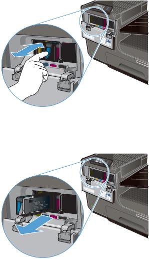
2.Push the old ink cartridge inward to unlock it.
Figure 1-8 Replace the ink cartridges (2 of 7)
3.Grasp the edge of the old ink cartridge, and then pull the cartridge straight out to remove it.
Figure 1-9 Replace the ink cartridges (3 of 7)
ENWW |
Removal and replacement procedures |
9 |
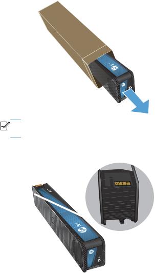
4.Remove the new ink cartridge from the packaging.
Figure 1-10 Replace the ink cartridges (4 of 7)


 NOTE: Do not touch the metal connector of the ink cartridge. Fingerprints on the connector can cause product operation problems.
Figure 1-11 Replace the ink cartridges (5 of 7)
10 Chapter 1 Removal and replacement |
ENWW |
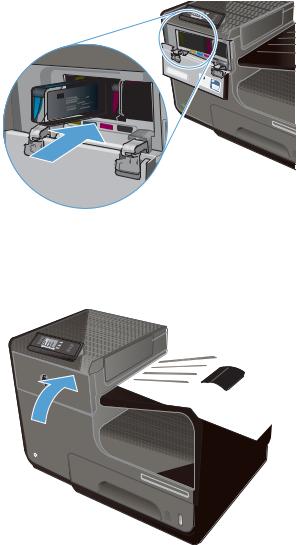
5.Insert the new ink cartridge into the product.
Figure 1-12 Replace the ink cartridges (6 of 7)
6.Close the ink cartridge door.
Figure 1-13 Replace the ink cartridges (7 of 7)
7.Place the old ink cartridge in the box, and refer to the HP recycling instructions at www.hp.com/ recycle.
ENWW |
Removal and replacement procedures 11 |
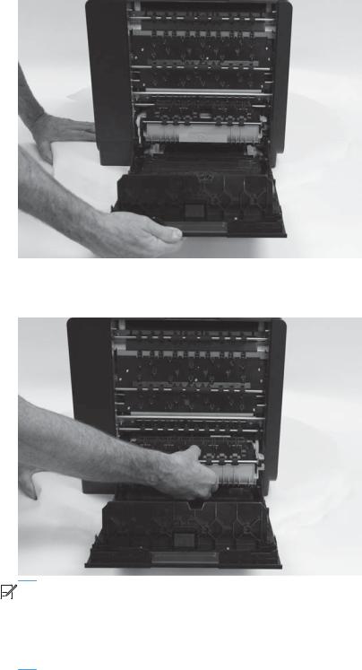
Duplex module
1.Open the left door.
Figure 1-14 Remove the duplex module (1 of 2)
2.Pull the duplex module out of the product.
Figure 1-15 Remove the duplex module (2 of 2)


 NOTE: When removing the duplex module, avoid making direct contact with the black cylinder to prevent ink smear on skin or clothes. Keep the duplex module level to avoid spilling any maintenance ink.
When removing the duplex module, do not let the bottom of the duplex module touch or rest on the ribs on the left door, which will damage them and might lead to paper damage and jams.
12 Chapter 1 Removal and replacement |
ENWW |
Output bin
▲Lift and remove the output bin.
Figure 1-16 Remove the output bin
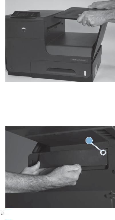
Output bin flap
1.Remove the output bin. See Output bin on page 13.
2.Flex the middle of the output bin flap, and then remove the flap by pulling the rear pin (callout 1) away from the product first.
Figure 1-17 Remove the output bin flap
1


 Reinstallation tip With the flap in the open position, insert the front pin into the product first,

 and then flex or bend the flap to install the rear pin.
ENWW |
Removal and replacement procedures 13 |
Menu access
These hidden engineering menus are used for testing and calibration. Some or all of them are referenced in remove and replace sections as required.
 WARNING! Misuse of these menus could damage the product or make it unusable.


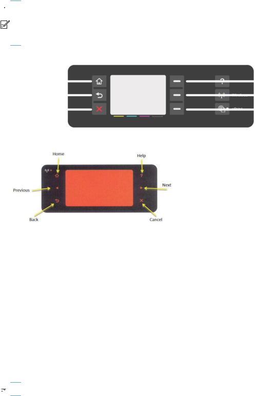
 NOTE: These buttons are not illuminated until they are touched with sufficient pressure. Locate these buttons by sweeping your finger over the general areas indicated in Figure 1-18 X451 control panel button locations on page 14.
Figure 1-18 X451 control panel button locations
HOME (TL) |
|
|
|
ATM 1 |
|
|
|||
PREVIOUS (BL) |
|
|
|
ATM 2 |
|
|
|||
CANCEL |
|
|
|
ATM 3 |
|
|
Figure 1-19 X551 control panel button locations
Access the Engineering menu
X451
1.Press the Cancel  button.
2.Press the Back  button.
3.Press the Cancel  button twice.
X551
1.Touch the Home  button.
2.Touch the Back  button.
3.Touch the Home  button twice to enter the Engineering menu.
 NOTE: The Service menu is accessed from the Engineering menu.
14 Chapter 1 Removal and replacement |
ENWW |

Access the Support Menu
X451
1.Press the Back  button.
2.Press the Cancel  button.
3.Press the Back  button twice.
X551
▲Touch the Back  button four times consecutively to open the Support Menu.
 NOTE: The Support Menu is usually used by HP call center agents for assisting customers.
Place the product into MFG (manufacturing) mode


 NOTE: These two modes are ONLY to be used by authorized service providers. They should NEVER be accessed by the end user.
X451
▲Press and hold the ATM1 and ATM3 buttons while plugging in the product.
X551
1.Press and hold the power button while plugging in the product. The HP logo appears on the product control panel, and then disappears. Continue to hold the power button for five seconds after the logo disappears.
2.Release the power button.
3.Touch the Home  button.
4.Touch the Back  button.
5.Touch the Home  button twice.
6.After a new screen appears, touch the Home  button again to enter MFG (off) mode.
7.Press the power button to enter MFG (on) mode.
Place the product into Audit mode


 NOTE: These two modes are ONLY to be used by authorized service providers. They should NEVER be accessed by the end user.
X451
▲Press and hold the ATM1 and ATM3 buttons while plugging in the product.
ENWW |
Removal and replacement procedures 15 |

X551
 WARNING! Audit mode is used only when the main PCA is replaced.
1.Press and hold the power button while plugging in the product. The HP logo appears on the control panel, and then disappears. Continue to hold the power button for five seconds after the logo disappears.
2.Release the power button.
3.Touch the Home button.
4.Touch the Back  button
5.Touch the Home  button twice.
6.Touch the  button.
7.Press the power button.


 NOTE: The product touchscreen is not active in this menu access mode. Use the
  and
and  buttons on the control panel frame.
16 Chapter 1 Removal and replacement |
ENWW |
Perform tap tests and interpret results
Perform a tap test
1.Open the Engineering Menu. See Access the Engineering menu on page 14.
2.Touch Manufacturing Menu.
3.Use the arrow key to find the Reports Menu, and then touch the OK button.
4.Use the arrow key to find the Print-mech tap tests, and then touch the OK button.
5.Use the arrow key to find the tap test to run.
10 tap test results (OOBE States)
The printed tap test results contain a sequence of numbers at line number 68, "Startup Complete," of the printed report.
Use the following table to interpret these numbers.
Table 1-1 |
10 tap test results, row 68 |
|
|
|
|
Column |
Code |
Acceptable values |
|
|
|
Column 1 |
DSID_PEN_PRINTER_STARTUP_BITS |
A value of 1 indicates that the printbar has been started up. |
|
|
This means that shipping fluid has been removed from the |
|
|
printbar and replaced with ink. This is the expected state for a |
|
|
printer after initialization. |
|
|
|
Column 2 |
DSID_OOBE_STATE |
255–OOBE messaging complete. |
|
|
|
Column 3 |
DSID_INK_SUPPLY_OOBE_COMPELTE |
1–SHF purge is complete and service wipes have been |
|
|
enabled. |
|
|
|
Column 4 |
DSID_CAL_OOBE_STATE |
A value of 2 means that the OOBE printed calibrations are |
|
|
complete. |
|
|
A value of 1 means the OOBE printed calibrations are in |
|
|
progress |
|
|
A value of 0 means the OOBE printed calibration does not |
|
|
exist so no printing/calibration for OOBE is attempted. |
|
|
|
Column 5 |
DSID_IQ_LIST_INDEX |
A value of 3 means that pen height and beam center have |
|
|
been completed, and that BDD is scheduled (or pending) to |
|
|
perform normally. |
|
|
NOTE: For 1315FR firmware and above. |
|
|
|
Column 6 |
DSID_BDD_FAIL_MASK |
0–internal use only. |
|
|
|
ENWW |
Removal and replacement procedures 17 |
Loading...