


Product End-of-Life Disassembly Instructions
Marketing Name / Model |
|
[List multiple models if applicable.] |
Product Category |
HP Omni100 PC |
Integrated PC |
|
|
|
|
|
|
|
|
|
|
Purpose: The document is intended for use by end-of-life recyclers or treatment facilities. It provides the basic instructions for the disassembly of HP products to remove components and materials requiring selective treatment.
 1.0 Items Requiring Selective Treatment
1.1Items listed below are classified as requiring selective treatment.
1.2Enter the quantity of items contained within the product which require selective treatment in the right column, as applicable.
|
Item Description |
|
|
Notes |
|
|
Quantity of items |
|
|
|
|
|
|
included in product |
|
||
|
|
|
|
|
|
|
|
|
|
Printed Circuit Boards (PCB) or Printed Circuit Assemblies (PCA) |
|
|
With a surface greater than 10 sq cm |
|
|
10 |
|
|
Batteries |
|
All types including standard alkaline and lithium coin or button style |
1 |
|
|||
|
|
|
|
batteries |
|
|
|
|
|
|
|
|
|
|
|||
|
Mercury-containing components |
|
|
For example, mercury in lamps, display backlights, scanner lamps, |
|
|
4 |
|
|
|
|
|
switches, batteries |
|
|
|
|
|
Liquid Crystal Displays (LCD) with a surface greater than 100 sq cm |
|
Includes background illuminated displays with gas discharge lamps |
1 |
|
|||
|
|
|
|
|
|
|
|
|
|
Cathode Ray Tubes (CRT) |
|
|
|
|
|
|
|
|
Capacitors / condensers (Containing PCB / PCT) |
|
|
|
|
|
|
|
|
|
|
|
|
|
|
|
|
|
Electrolytic Capacitors / Condensers measuring greater than 2.5 cm |
|
|
|
|
|
|
|
|
in diameter or height |
|
|
|
|
|
|
|
|
External electrical cables and cords |
|
|
|
|
|
|
|
|
|
|
|
|
|
|
|
|
|
Gas Discharge Lamps |
|
|
|
|
|
|
|
|
Plastics containing Brominated Flame Retardants |
|
|
|
|
|
|
|
|
|
|
|
|
|
|
||
|
Components and parts containing toner and ink, including liquids, |
|
|
Include the cartridges, print heads, tubes, vent chambers, and service |
|
|
|
|
|
semi-liquids (gel/paste) and toner |
|
|
stations. |
|
|
|
|
|
Components and waste containing asbestos |
|
|
|
|
|
|
|
|
|
|
|
|
|
|
|
|
|
Components, parts and materials containing refractory ceramic fibers |
|
|
|
|
|
|
|
|
Components, parts and materials containing radioactive substances |
|
|
|
|
|
|
|
|
|
|
|
|
|
|
|
|
 2.0 Tools Required
List the type and size of the tools that would typically be used to disassemble the product to a point where components and materials requiring selective treatment can be removed.
|
Tool Description |
|
Tool Size (if applicable) |
|
|
|
|
 screw driver
 3.0 Product Disassembly Process
3.1 List the basic steps that should typically be followed to remove components and materials requiring selective treatment:
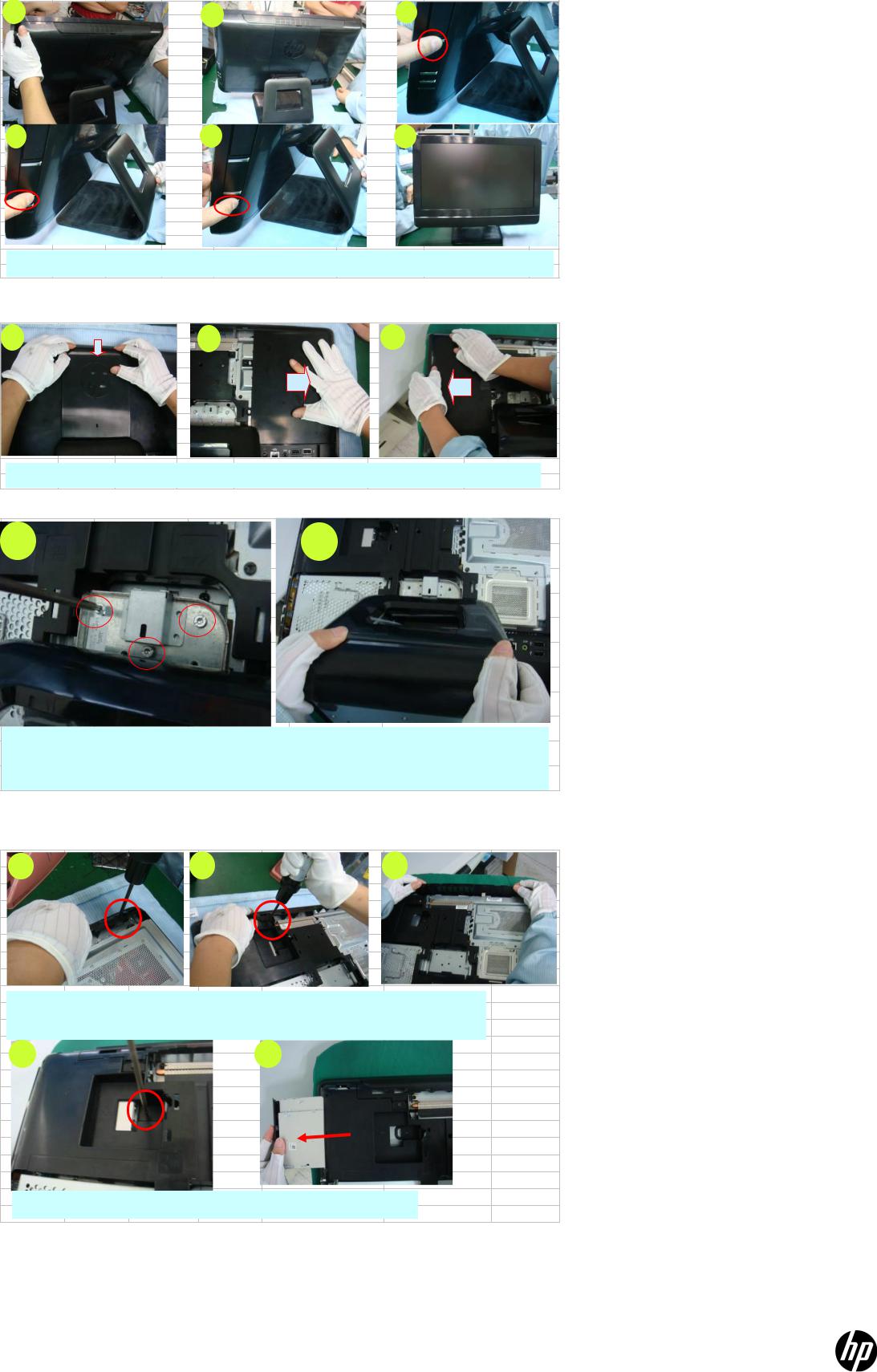
1.Place the system
2.Disassemble hinge cover & access door
3.Disassemble stand
4.Remove ODD&TOP Perf
5.Disassemble rear cover
6.Disassemble HDD
7.Disassemble CPU&I/O Shielding
8.Disassemble speaker
9.Disassemble stand support
10.Disassemble CPU H/S
11.Disassemble FAN
12.Unplug cable
13.Disassemble WLAN
14.Disassemble INVERTER
15.Disassemble MB
16.Remove power switch card
17.Disassemble webcam & antenna cable
18.Separate BASE pan& bezel
3.2 Optional Graphic. If the disassembly process is complex, insert a graphic illustration below to identify the items contained in the product that require selective treatment (with descriptions and arrows identifying locations).
1 |
2 |
3 |
4 |
5 |
6 |
Do cosmetic check then place unit on work table.
19. Disassemble hinge cover & access door
1 |
2 |
3 |
Disassemble hinge cover & R/L access door.
20. Disassemble stand
1 |
2 |
1
3
2
Remove 3 screws for fixing stand.
Place stand to specified area.
21. Remove ODD&TOP Perf
1 |
2 |
3 |
Remove 2 screws for fixing top perf.
Take top perf.
4 |
5 |
Remove one screw for fixing ODD, Put ODD to specified area.
22. Disassemble rear cover

1 |
|
|
|
3 |
1 |
|
|
|
|
|
|
1 |
2 |
5 |
|
4 |
|
|
|
2 |
|||
|
|
|
3 |
2 |
|
|
|
|
|
|
3
Remove 5 screws for locking rear cover. Remove rear cover as sequence shows in pic3
6) Disassemble HDD
1
2
|
|
1.Remove 1pcs screw for |
|
Hold unit with right hand, remove HDD |
|
||||||
|
|
|
|||||||||
|
|
fixing HDD |
|
with left hand, Put HDD to specified |
|
||||||
|
|
|
|||||||||
|
|
|
|
|
|
|
|
|
|
|
|
7) Disassemble CPU&I/O Shielding |
|
|
|
|
|
|
|
||||
|
|
|
|
|
|
|
|
||||
2 |
1 |
|
2 |
3 |
|
|
|||||
1 |
|
|
|
|
|
|
|
|
|
||
|
|
|
|
|
|
|
|
|
|
|
|
|
|
|
|
|
5 |
4 |
3 |
|
|
|
|
7
6
|
Remove 7 screws for fixing CPU shielding & I/O |
|
Remove CPU shiedling. |
|
|
|
|
|
|
|
|
5 |
|
|
|
|
|
4 |
|
|
|
|
|
|
|
|
|
|
|
|
|
|
|
|
|
|
|
|
|
|
|
|
|
|
|
|
|
|
|
|
|
|
|
|
|
|
|
|
|
|
|
|
|
|
|
|
|
|
|
|
|
Remove DDR cover. |
|
Remove I/O shiedling. |
|
||
|
|
|
8) Disassemble speaker
1 |
2 |
3 |
1 |
2 |
3 |
4 |
|
|
|
|
Remove 4pcs screws for fixing speaker. |
|
|
|
|
|
|
||||
|
|
|
Unplug speaker cable. |
|
|||||||
|
|
||||||||||
|
|
|
|
|
|
|
|
|
|
|
|
|
|
|
|
|
Take R/L speaker out. |
|
|
||||
4 |
|
|
|
|
|||||||
|
|
|
|
|
|
|
|
|
|
|
|
|
|
|
|
|
|
|
|
|
|
|
|
|
|
|
|
|
|
|
|
|
|
|
|
|
|
|
|
|
|
|
|
|
|
|
|
|
|
|
|
|
|
|
|
|
|
|
|
|
|
|
|
|
|
|
|
|
|
|
|
|
|
|
|
|
|
|
|
|
|
|
|
|
|
|
|
|
|
|
|
|
|
|
|
9) Disassemble stand support
 Loading...