


omnibook 4100

®
HP OmniBook 4100/4150
Service Manual
For other Service and User Manuals, go to www.ManualDepot.com

ii HP OmniBook 4100/4150
Notice
In a continuing effort to improve the quality of our products, technical and environmental information
in this document is subject to change without notice.
This manual and any examples contained herein are provided “as is” and are subject to change without
notice. Hewlett-Packard Company makes no warranty of any kind with regard to this manual,
including, but not limited to, the implied warranties of merchantability and fitness for a particular
purpose. Hewlett-Packard Co. shall not be liable for any errors or for incidental or consequential
damages in connection with the furnishing, performance, or use of this manual or the examples herein.
Consumer transactions in Australia and the United Kingdom: The above disclaimers and limitations
shall not apply to Consumer transactions in Australia and the United Kingdom and shall not affect the
statutory rights of Consumers.
© Copyright Hewlett-Packard Company 1998, 1999. All rights reserved. Reproduction, adaptation, or
translation of this manual is prohibited without prior written permission of Hewlett-Packard Company,
except as allowed under the copyright laws.
The programs that control this product are copyrighted and all rights are reserved. Reproduction,
adaptation, or translation of those programs without prior written permission of Hewlett-Packard Co.
is also prohibited.
Portions of the programs that control this product may also be copyrighted by Microsoft Corporation,
SystemSoft Corp., Crystal Semiconductor Corporation, Phoenix Technologies, Ltd., ATI
Technologies Inc., and NeoMagic, Inc. See the individual programs for additional copyright notices.
Microsoft, MS, MS-DOS, Windows and Windows NT are registered trademarks of Microsoft
Corporation. Pentium and the Intel Inside logo are U.S. registered trademarks and MMX is a U.S.
trademark of Intel Corporation. TrackPoint is a U.S. registered trademark of International Business
Machines.
All certifications may not be completed at product introduction. Check with your HP reseller for
certification status.
This equipment is subject to FCC rules. It will comply with the appropriate FCC rules before final
delivery to the buyer.
Hewlett-Packard Company
Mobile Computing Division
19310 Pruneridge Ave.
Cupertino, CA 95014, U.S.A.
Edition History
Edition 1............................April 1998
Edition 2........................October 1998
Edition 3........................January 1999
Edition 4....................September 1999

HP OmniBook 4100/4150 iii
Contents
1.
Product Information......................................................................................................1-1
Features and Operation.................................................................................................................1-3
Turning the OmniBook On and Off....................................................................................... 1-4
Checking the Status of the OmniBook................................................................................... 1-5
Using Fn Hot Keys.................................................................................................................1-6
Resetting the OmniBook........................................................................................................ 1-6
System Resources.................................................................................................................. 1-7
Specifications................................................................................................................................ 1-9
Internal Design............................................................................................................................ 1-14
Removal and Replacement............................................................................................2-1
Removing the Battery or Plug-In Module (User-Replaceable)..................................................... 2-3
Removing a RAM Board (User-Replaceable)............................................................................. 2-4
Removing the Hard Disk Drive (User-Replaceable).................................................................... 2-5
Replacing Small Parts (User-Replaceable)................................................................................... 2-8
Removing the Keyboard (HP Authorized Service Providers Only)............................................. 2-9
Removing the Display Assembly (HP Authorized Service Providers Only).............................. 2-11
Removing the LCD Module (HP Authorized Service Providers Only)......................................2-13
Removing the Top Case (HP Authorized Service Providers Only)............................................ 2-16
Removing the CPU Module (HP Authorized Service Providers Only)...................................... 2-19
Removing the Motherboard or Bottom Case (HP Authorized Service Providers Only)............ 2-24
Removing or Repairing the BIOS IC (HP Authorized Service Providers Only)........................ 2-29
Removing Other Components (HP Authorized Service Providers Only)...................................2-31
Troubleshooting and Diagnostics..................................................................................3-1
Troubleshooting............................................................................................................................ 3-2
Troubleshooting the Problem................................................................................................. 3-2
Verifying the Repair ..............................................................................................................3-3
Suggestions for Troubleshooting........................................................................................... 3-4
Diagnostic Tools......................................................................................................................... 3-13
OmniBook Diagnostic Program........................................................................................... 3-13
Power-On Self-Test ............................................................................................................. 3-20
Sycard PCCtest 450 CardBus Card (Optional).................................................................... 3-23
Desktop Management Interface (DMI)................................................................................ 3-24
BIOS Setup Utility............................................................................................................... 3-26
Replaceable Parts...........................................................................................................4-1
Reference Information...................................................................................................5-1
Password Removal Policy............................................................................................................ 5-1
Hewlett-Packard Display Quality Statement................................................................................ 5-2
Service Notes and Obsolete Parts................................................................................................. 5-6

iv HP OmniBook 4100/4150
Figures
Figure 1-1. OmniBook - Front View....................................................................................................1-3
Figure 1-2. OmniBook - Side View .....................................................................................................1-3
Figure 1-3. OmniBook - Rear View.....................................................................................................1-4
Figure 1-4. Replaceable Module Diagram.........................................................................................1-14
Figure 2-1. Removing the Battery or Plug-In Module..........................................................................2-3
Figure 2-2. Removing a RAM Board...................................................................................................2-4
Figure 2-3. Removing the Hard Disk Drive.........................................................................................2-5
Figure 2-4. Installing a Hard Drive in the Cover..................................................................................2-6
Figure 2-5. Removing the Keyboard....................................................................................................2-9
Figure 2-6. Removing the Display .....................................................................................................2-11
Figure 2-7. Removing the LCD Module ............................................................................................2-15
Figure 2-8. Removing the Top Case...................................................................................................2-17
Figure 2-9. Removing the CPU (OmniBook 4150†)..........................................................................2-21
Figure 2-10. Inserting the CPU (OmniBook 4100/4150†).................................................................2-22
Figure 2-11. Positioning Thermal Pads..............................................................................................2-23
Figure 2-12. Removing the Motherboard...........................................................................................2-26
Figure 2-13. Installing Docking Doors and Module Latch.................................................................2-28
Figure 2-14. Example of Serial Number Label ..................................................................................2-28
Figure 2-15. Removing the BIOS IC..................................................................................................2-29
Figure 2-16. Boot-Block Jumper........................................................................................................2-31
Figure 3-1. Basic Troubleshooting Steps.............................................................................................3-2
Figure 3-2. OmniBook Diagnostic Screens — Basic and Advanced.................................................3-13
Figure 3-3. Serial and Parallel Loopback Connectors........................................................................3-15
Figure 4-1. Exploded View..................................................................................................................4-2
Figure 4-2. Display Components..........................................................................................................4-7
Figure 4-3. Motherboard Components.................................................................................................4-8
Tables
Table 1-1. Product Comparisons..........................................................................................................1-1
Table 1-2. OmniBook 4100/4150 Series Models.................................................................................1-2
Table 1-3. Activating Power Modes.....................................................................................................1-4
Table 1-4. Main Status Lights (LED Strip Cable)................................................................................1-5
Table 1-5. Keyboard Status Lights (VGA PCA or Motherboard)........................................................1-5
Table 1-6. Fn Hot Keys........................................................................................................................1-6
Table 1-7. System Interrupts ................................................................................................................1-7
Table 1-8. System Memory..................................................................................................................1-7
Table 1-9. System Input/Output Addresses (100-3FF).........................................................................1-8
Table 1-10. DMA Channels.................................................................................................................1-8
Table 1-11. OmniBook 4100/4150 Series Specifications....................................................................1-9
Table 1-12. OmniBook 4100/4150 Series Accessories......................................................................1-12
Table 1-13. Functional Structure........................................................................................................1-15
Table 2-1. Removal Cross-Reference...................................................................................................2-1
Table 2-2. Required Equipment...........................................................................................................2-2
Table 2-3. Recommended Screw Torques............................................................................................2-2
Table 2-4. RAM Board Replacement Part Numbers............................................................................2-4
Table 2-5. Hard Disk Drive Replacement Part Numbers.....................................................................2-5
Table 2-6. Replacing Small Parts (User-Replaceable).........................................................................2-8
Table 2-7. Display Component Compatibility....................................................................................2-13
Table 2-8. CPU Component Compatibility........................................................................................2-19

HP OmniBook 4100/4150 v
Table 2-9. Removing Display Components....................................................................................... 2-31
Table 2-10. Removing Top Case Components.................................................................................. 2-32
Table 2-11. Removing Bottom Case Components............................................................................ 2-33
Table 3-1. Scope of Diagnostic Tools................................................................................................. 3-4
Table 3-2. Troubleshooting Suggestions............................................................................................. 3-5
Table 3-3. OmniBook Diagnostic Error Codes................................................................................. 3-15
Table 3-4. POST Terminal-Error Beep Codes.................................................................................. 3-20
Table 3-5. POST Messages............................................................................................................... 3-21
Table 3-6. Sycard PCCTest Commands............................................................................................ 3-23
Table 3-7. BIOS Setup Menus and Parameters................................................................................. 3-26
Table 4-1. OmniBook Replaceable Parts ............................................................................................ 4-3
Table 4-2. Assembly-Component Breakdown..................................................................................... 4-8
Table 4-3. Accessory Replaceable Parts..............................................................................................4-9
Table 4-4. Part Number Reference.................................................................................................... 4-10
Table 5-1. OmniBook 4100/4150 LCD Guidelines (TFT).................................................................. 5-3
Table 5-2. Service Notes ..................................................................................................................... 5-6
Table 5-3. Obsolete Repair Parts......................................................................................................... 5-6

vi HP OmniBook 4100/4150
Introduction
This service manual provides reference information for the HP OmniBook 4100/4150. It is intended to
be used by HP-authorized service personnel in the installation, servicing, and repair of these products.
The manual is designed as a self-paced guide. It is intended to train you to install, configure, and
repair OmniBook computers. You can follow this manual without having equipment available.
The following table lists additional places where you can get supplementary information about
OmniBook products.
Sources of OmniBook Information
Source Address or Number Comments
HP External Web http://www.h p.com/omnibook
(http://www.europe.hp.com/omnibook,
European mirror)
No usage restriction.
HP US Reseller Web http://partner.americas.hp.com Restricted to Authorized Resellers
only.
HP Asia Pacific Channel
Support Centre for DPSP
Partners
http://www.h p.com.au Restricted to DPSP Partners only.
America Online Keyword: HP Call (800) 827-6364 for membership
within the US.
CompuServe GO HP Call (800) 524-3388 for membership
within the US.
HP Bulletin Board Service Refer to the latest Product Support
Plan for non-US BBS numbers.
HP Support Assist CD-ROM (800) 457-1762 US and Canada.
(801) 431-1587 Outside US and Canada.
Microsoft Web http://www.microsoft.com Information and updates for Windows
operating systems.

HP OmniBook 4100/4150 Product Information 1-1
1
Product Information
The HP OmniBook 4100/4150 provides desktop performance and expandability as well as convenient
portability. It uses high-performance component technologies that make it capable of replacing a
desktop computer or serving as a portable multimedia presentation tool.
Table 1-1. Product Comparisons
OmniBook 7100/7150 OmniBook 4100/4150 OmniBook 2100/3100 OmniBook 900
Processor *
Intel Pentium II (300 or
266 MHz).
Pentium II (233 to 400
MHz), or Pentium (266
MHz).
Pentium II (300, 266,
or 233 MHz), or
Pentium (266, 233, or
200 MHz).
Intel Pentium II (366 or
300(PE) MHz).
Memory
64 MB RAM in system
slot or 32 MB RAM on
motherboard.
Expandable to 320 or
288 MB.
128 or 64 MB RAM in
slot or 32 MB RAM on
motherboard.
Expandable to 256 or
160 MB.
32 MB RAM on
motherboard.
Expandable to 160,
192, or 288 MB.
32 MB RAM on
motherboard.
Expandable to
160 MB.
Display
14.1-inch TFT XGA
display.
14.1- or 13.3-inch TFT
XGA display.
13.3-inch TFT XGA
display, or 12.1-inch
TFT or DSTN SVGA
display.
12.1-inch TFT SVGA
display.
Video
AGP or PCI local bus
video.
64-bit graphics
controller with 4 MB
external video RAM,
3Dgraphics
acceleration.
Up to 16M colors
(XGA).
Zoomed Video
enabled.
AGP or PCI local bus
video.
256- or 128-bit
graphics controller with
8, 4, 2.5 or 2 MB
internal video RAM.
Up to 16M or 64K
colors (XGA).
Zoomed Video
enabled.
PCI local bus video.
128-bit graphics
controller with 2 MB
internal video RAM.
Up to 64K colors
(XGA), 16M colors
(SVGA).
Zoomed Video
enabled.
AGP video.
256-bit graphics
controller with 2.5 MB
internal video RAM.
Up to 16M colors
(XGA).
Zoomed Video
enabled.
Operating
System
Windows 95,
Windows 98, or
Windows NT 4.0
preinstalled.
Windows 95,
Windows 98, or
Windows NT 4.0
preinstalled.
Windows 95,
Windows 98, or
Windows NT 4.0
preinstalled.
Windows 95,
Windows 98, or
Windows NT 4.0
preinstalled.
Desktop
Management
Interface
DMI 2.0.
HP TopTools 2.6 or
3.0.
DMI 2.0.
HP TopTools 2.6 to
4.5.
DMI 2.0.
HP TopTools 2.6 or
3.0.
DMI 2.0.
HP TopTools 3.0.
Power
Management
APM 1.2.
ACPI compliant.
APM 1.2.
ACPI compliant.
APM 1.2.
ACPI compliant.
APM 1.2.
ACPI compliant.
Power States
On, Standby, Suspend,
Hibernate, Off.
On, Standby, Suspend,
Hibernate, Off.
On, Standby, Suspend,
Hibernate, Off.
On, Standby, Suspend,
Hibernate, Off.
* Intel Mobile Pentium processor.

1-2 Product Information HP OmniBook 4100/4150
Table 1-2. OmniBook 4100/4150 Series Models
OmniBook
Product *
CPU ** Display Hard Drive Floppy Drive CD-ROM
Drive
Standard
RAM
OmniBook 4100
F1462
x
Pentium II
233 MHz
13.3-inch
XGA TFT
4 GB
(F1467A)
1.44 MB
(F1472A)
CD-ROM
(F1474A)
32 MB
F1463
x
*** Pentium
266 MHz
14.1-inch
XGA TFT
F1464
x
Pentium II
266 MHz
6 GB
(F1475A)
F1479
x
4 GB
(F1467A)
F1703
x
13.3-inch
XGA TFT
OmniBook 4150 Series
F1629
x
Pentium II
300 MHz
14.1-inch
XGA TFT
6 GB
(F1475A)
1.44 MB
(F1472A)
CD-ROM
(F1474A)
64 MB
(F1457A)
F1640
x
Pentium II
333 MHz
F1641
x
Pentium II
366 MHz
F1642
x
10 GB
(F1744A)
DVD Drive
(F1653A)
128 MB
(F1622A)
F1647
x
Pentium II
300 MHz
4.8 GB
(none)
CD-ROM
(F1474A)
64 MB
(F1457A)
F1648
x
Pentium II
400 MHz
10 GB
(F1744A)
DVD Drive
(F1653A)
F1658
x
B
Pentium II
366 MHz
13.3-inch
XGA TFT
4.8 GB
(none)
CD-ROM
(F1474A)
64 MB
(F1457B)
F1660
x
B
Pentium II
400 MHz
14.1-inch
XGA TFT
6 GB
(F1475A)
F1663
x
Pentium II
366 MHz
4.8 GB
(none)
64 MB
(F1457A)
This table lists only base product configurations—custom configurations are not included.
* For the products listed:
"
x
" suffix means
"N", "NT", “NV”, “NG” for Windows NT 4.0 installed (marketing distinction only), or
"W", "WT", “WV”, “WG”, “WR” for Windows 95 or Windows 95/98 installed (marketing distinction only).
** Intel Mobile Pentium or Pentium II processor.
*** Available only with Spring ’98 software—other OmniBook 4100 products rolled to Fall ’98 software. All
OmniBook 4150 products were released with Fall ’98 software or later.
B
The OmniBook 4150 Series has two classes of products with different internal designs, different software
drivers, and different BIOSes. Models marked with
B
have “4150 B” after the serial number and are called
4150B in this manual—other OmniBook 4150 models listed in this table are called 4150† in this manual,
and they have no marking after the serial number.

HP OmniBook 4100/4150 Product Information 1-3
Features and Operation
The following three illustrations point out the main external features of the computer. They are
followed by highlights of the computer’s operation. For an internal, exploded view, see page 4-2.
Figure 1-1. OmniBook - Front View
Figure 1-2. OmniBook - Side View
Audio jacks
Keyboard status lights
Microphone
Power button
Pointing stick
Touch pad
Speaker
Click buttons
(above and below
the touch pad)
Module latch
PC Card slots
PC Card eject buttons
Speaker
Latch
Main status lights
PS/2 port
USB port
System-off button
Speaker
Module latch
Plug-in module bay
Battery
AC adapter socket
Mute button

1-4 Product Information HP OmniBook 4100/4150
Figure 1-3. OmniBook - Rear View
Turning the OmniBook On and Off
• On. Press the blue power button to turn on the OmniBook.
•
Standby. The display turns off automatically if the computer is inactive for about 2 minutes.
•
Suspend. Click Start, Suspend (Windows 95) or press the blue power button briefly (about 1
second) to suspend activity when the OmniBook is on. When you turn on the computer, it
resumes your previous work session.
Closing the lid (for more than 2 seconds) also suspends the computer.
•
Hibernate. Press Fn+F12. This is like Off, except that your current work session is first saved to
disk. When you turn on the computer, it reboots and restores your previous session.
• Off. Click Start, Shut Down. If the OmniBook does not respond, press and hold the blue power
button until the display shuts down. When you turn on the computer, it reboots. Unsaved data is
lost.
Table 1-3. Activating Power Modes
Power Mode To Enter Mode To Turn Back On
Standby
Reduced-power/stopped state. Display is off.
Everything is in a reduced-power state. Network
devices are maintained. Your current work session
continues at turn-on (any key or pointer action).
Press Fn+S (not Windows 98)
–or–
allow time-out.
Press any key or
move a pointing
device to display
the current session
("Instant-On").
Suspend
Low-power/stopped state. Lower power state than
Standby. Everything is off or in a low-power state.
Network devices are off. Your previous work
session resumes at turn-on. For plug-and-play
operating systems, network connections resume at
turn-on.
Press blue power button for about
1 second
–or–
click Start, Shut Down, Standby
(Windows 98)
–or–
click Start, Suspend (Windows 95)
–or–
allow time-out.
Press blue power
button to display
the current session
("Instant-On").
Hibernate
No-power/stopped state. Session is saved on the
hard disk. Everything is shut down. Computer
reboots at turn-on and restores previous session
and network connections (if plug-and-play).
Press Fn+F12
–or–
allow time-out.
Press blue power
button to restart
and restore the
previous session.
Off
No-power/stopped state. Everything is shut down
(battery continues charging if ac adapter is
connected). Computer reboots at turn-on and
restores network connections.
Click Start, Shut Down
–or–
Press and hold the blue power
button until the display shuts down.
Press blue power
button to restart
with a new session.
Infrared
port
Kensington
lock slot
Parallel
port
Serial
port
VGA
out
Docking
port

HP OmniBook 4100/4150 Product Information 1-5
Checking the Status of the OmniBook
The main OmniBook status lights, located at the front-right edge of the display bezel at the top of the
display, indicate power status and drive activity. (These lights are on the LED strip cable.)
Table 1-4. Main Status Lights (LED Strip Cable)
Meaning
Power mode
Steady green light: OmniBook is running (On mode).
Steady orange light: OmniBook is suspended (Suspend or Standby mode).
No light: OmniBook is off (Off or Hibernate mode).
Green and orange lights: OmniBook failed when resuming.
Drive access
Green light: OmniBook is accessing the hard disk drive, floppy disk drive, or a drive
in the plug-in module bay. For the OmniBook 4100, it also indicates PC Card
activity.
Charging
Steady green light: AC adapter is connected, battery is full or stopped charging.
Blinking green light: AC adapter is connected, battery is charging.
No light: AC adapter is not connected or battery is not present.
The keyboard status lights, located above the keyboard, indicate the states of the keyboard locks.
(These lights are on the VGA PCA for the OmniBook 4100, and on the motherboard for the
OmniBook 4150 Series.)
Table 1-5. Keyboard Status Lights (VGA PCA or Motherboard)
Meaning
Caps Lock
Caps Lock is active.
Keypad Lock
The embedded keypad is active (Fn+F8 or Fn held down). Num Lock must also be
on for the numeric keys—otherwise, cursor control is active.
Num Lock
Num Lock is active.
In addition, the battery module has five lights that indicate its charge level. To view the lights, you
have to remove the battery and press the pad on the back next to the connector. The number of lights
that turn on indicates the charge.

1-6 Product Information HP OmniBook 4100/4150
Using Fn Hot Keys
The Fn key combined with another key is a hot key—a shortcut key sequence for various system
controls. For an external keyboard, CTRL+ALT is normally equivalent to the Fn key.
Table 1-6. Fn Hot Keys
Hot Key Effect
Fn + F1 Decreases the display’s brightness.
Fn + F2 Increases the display’s brightness.
Fn + F3 Decreases the display’s contrast (non-TFT displays only).
Fn + F4 Increases the display’s contrast (non-TFT displays only).
Fn + F5 Switches among the built-in display, an external display, and simultaneous displays.
Fn + F8 Toggles the embedded keypad on and off. Does not affect an external keyboard. If
Num Lock is on, then the numeric functions are active—otherwise, cursor control is
active.
Fn + F12 Enters Hibernate mode.
Fn + R Enters Suspend mode.
Fn + S Enters Standby mode (Windows 95, Windows NT) or Suspend mode (Windows 98).
Fn + ScrLk Toggles Scroll Lock on and off.
Fn + UP ARROW
Fn + DOWN ARROW
Increases and decreases the sound volume.
Resetting the OmniBook
1. Use a pen or a straightened paper clip to push the system-off button on the left side of the
OmniBook. (The switch is on the motherboard.)
–or–
Press and hold the blue power button until the display shuts down. (The switch is on the
motherboard.)
2. After the computer shuts down, press the blue power button to turn it back on.
Note
The OmniBook can boot from a CD if all these conditions are true:
• You have an internal CD-ROM or DVD drive installed,
• You have a bootable CD in the drive, such as the OmniBook Recovery CD, and
• You select the CD-ROM or DVD drive as the boot device. You can do this during reboot by
pressing ESC to cancel the OmniBook screen, then ESC to display the boot-device menu for
a one-time selection.

HP OmniBook 4100/4150 Product Information 1-7
System Resources
Below are default values for system resources. To see other, non-default possibilities, use the BIOS
Setup utility (see page 3-26), which lists port and audio device configurations in the System Devices
menu.
The tables in this section show typical resource usage as set up by the OmniBook BIOS. Plug-and-
play operating systems, drivers, and BIOS Setup settings may change some of the entries.
Table 1-7. System Interrupts
0 System timer
1 Keyboard
2 Cascade IRQ 9
3 Free (or COM2 infrared port, if enabled)
4 COM1 (serial port)
5 Audio
6 Floppy drive
7 LPT1 (ECP parallel port)
8 Real-time clock
9 Free (OmniBook 4100/4150B)
Video (OmniBook 4150†)
10 USB and CardBus - assigned by Windows driver
Video Controller (OmniBook 4150B)
11 Free
12 Pointing device
13 Numeric data processor
14 Internal hard disk (primary IDE controller)
15 Internal CD-ROM drive (secondary IDE controller)
† Models called 4150† in this manual have no marking in the serial number,
whereas models called 4150B have 4150 B after the serial number.
Table 1-8. System Memory
00000 - 9FFFF System memory
A0000 - BFFFF Video
C0000 - CBFFF
C0000 - CFFFF
Video BIOS (OmniBook 4100/4150†)
Video BIOS (OmniBook 4150B)
CC000 - DBFFF*
D0000 - DBFFF*
Free** (OmniBook 4100/4150†)
Free** (OmniBook 4150B)
DC000*- FFFFF System BIOS
* Approximate boundary.
** Valid uses for memory addresses CC000-DBFFF or D0000-DBFFF:
Upper memory blocks (UMBs).
PC card memory windows.
† Models called 4150† in this manual have no marking in the serial number,
whereas models called 4150B have 4150 B after the serial number.

1-8 Product Information HP OmniBook 4100/4150
Table 1-9. System Input/Output Addresses (100-3FF)
120-127 Audio (OmniBook 4150† only)
170-177 Internal CD-ROM drive (secondary IDE controller)
1F0-1F7 Internal hard disk (primary IDE controller)
220-22F Audio
376 Internal CD-ROM drive (secondary IDE controller)
378-37F LPT1 (printer port)
388-38B Audio
3B0-3BB VGA adapter
3C0-3DF VGA adapter
3E0-3E1 PCMCIA controller
3F0-3F5 Floppy controller
3F6 Internal hard disk (primary IDE controller)
3F7 Floppy controller
3F8-3FF COM1 (serial port)
† Models called 4150† in this manual have no marking in the serial number,
whereas models called 4150B have 4150 B after the serial number.
Table 1-10. DMA Channels
0 Sound record (OmniBook 4100/4150†)
Free (OmniBook 4150B)
1 Sound playback
2 Floppy drive
3 LPT1 (ECP parallel port)
4 Cascade
5 Free
6 Free
7 Free
† Models called 4150† in this manual have no marking in the serial number,
whereas models called 4150B have 4150 B after the serial number.

HP OmniBook 4100/4150 Product Information 1-9
Specifications
The following tables list descriptions for the OmniBook and its accessories.
Table 1-11. OmniBook 4100/4150 Series Specifications
Physical Attributes
Size: 330.5mm×256.9mm×35-36.5mm (13.0"×10.1"×1.3-1.4").
Weight: 2.92-2.99 kg (6.45-6.60 lb.).
Processor and
Bus Architecture
300/333/366/400 MHz Pentium II processor with internal 256 KB 4-way, set-
associative L2 cache.
–or–
233/266/300-MHz Intel Pentium II, or 266-MHz Intel Pentium processor with 512-KB
pipeline-burst-synchronous L2 cache.
1.6- to 1.8-V core, 2.5-V external, low-power processor.
32-KB (16-KB instruction, 16-KB data) L1 cache.
32-bit PCI bus.
Graphics
14.1- or 13.3-inch XGA active-matrix (TFT) display.
Zoomed Video support for lower PC Card slot.
OmniBook 4150B:
ATI Mobility-M or -M1 graphics accelerator with 4- or 8-MB video RAM (1024 ×
768 × 16M colors).
2X AGP graphics capability.
OmniBook 4150†:
256-bit NeoMagic MagicGraph graphics accelerator with 2.5-MB video RAM (1024
× 768 × 16M colors).
1X AGP graphics capability.
OmniBook 4100:
128-bit NeoMagic MagicGraph graphics accelerator with 2-MB video RAM (1024 ×
768 × 64K colors).
Zoomed Video support for both PC Card slots.
Power
Rechargeable 9-cell lithium ion battery with LED charge-level gauge (10.8 Vdc,
4.2 AH or more, 45 watt-hours or more).
Battery life (one battery): up to 3-4 hours typical (varies with type of usage and
model).
Fast battery recharge: 80% in 1.5-2 hours, 100% in 2-2.5 hours.
Low-battery warning.
Suspend/resume capability.
60-watt ac adapter: 100 to 240 Vac (50 to 60 Hz) input, 19 Vdc, 3.16 A output.
Mass Storage
4, 6, or 10 GB removable hard drive.
Standard 1.44-MB floppy drive module.
Standard 24X CD-ROM drive module or DVD drive module.
Optional LS-120 SuperDisk module.
Optional DVD drive.
Optional 10 GB second hard drive module.
RAM OmniBook 4150† or 4150B:
128 MB or 64 MB SDRAM in first RAM slot.
Two total slots for RAM expansion up to 256 MB (using 128 MB modules).
66 MHz RAM bus, or 100 MHz RAM bus for OmniBook 4150B.
OmniBook 4100:
32-MB SDRAM on motherboard.
One slot for RAM expansion up to 160 MB.
66 MHz RAM bus.

1-10 Product Information HP OmniBook 4100/4150
Audio System
16-bit, Sound Blaster Pro-compatible.
SRS 3D enhanced audio.
Stereo sound via two built-in speakers.
Built-in microphone.
Line-in, headphone-out, and microphone-in.
Keyboard and
Pointing Device
87/88-key touch-type QWERTY keyboard with 101/102 key emulation.
Embedded numeric keypad.
12 function (Fn) keys.
Two pointing devices: pointing stick (technology licensed from IBM) and touch pad.
Input/Output
FDD/IDE interface for external module bay.
Universal serial bus (USB).
9-pin, 115,200-bps serial (16550 UART).
25-pin bi-directional ECP/EPP parallel.
Video-out (up to 1024×768×64K colors, or up to 1600×1200×64K or 16M colors for
OmniBook 4150B. Refresh rate 60 to 85-Hz).
Dual display.
PS/2 keyboard/mouse.
4-Mbps IrDA-compatible infrared port.
Expandability
One Type III or two Type II 16-/32-bit PC Card slots (3.3- and 5-V support).
CardBus enabled.
Plug-in module bay for accessory modules.
Optional port replicator, mini dock, and docking system.
Preinstalled Software
Microsoft Windows 95, Windows 98, or Windows NT 4.0.
Windows 95/98-compatible Plug-and-Play.
Windows NT 4.0 APM and PC Card Plug-and-Play.
Advanced Power Management (APM 1.2).
DMI 2.0 with HP TopTools 2.6 to 4.5
DiagTools.
Agate Tioman for HP (Hot Swap).
Adobe Acrobat Reader.
Virus Scan software.
Online documentation.
OmniBook Recovery CD-ROM included.
Centralized worldwide BIOS and driver update service.
Security Features
User and administrator passwords.
System, hard drive, and docking passwords.
PC identification displayed at boot.
DMI-accessible electronic serial number.
Kensington Microsaver lock slot.
Environmental Limits
Operating temperature: 5 to 35 °C (41 to 95 °F).
Operating humidity: 20 to 90 percent RH (5 to 35 °C).
Storage temperature: –20 to 50 °C (–4 to 122 °F).

HP OmniBook 4100/4150 Product Information 1-11
Major ICs OmniBook 4150B:
CPU: Intel Mobile Pentium II.
South Bridge: PIIX4M.
Video: ATI Mobility-M or -M1.
Audio: ESS ES1978 Maestro-2E and ESS ES1921.
CardBus: TI PCI 1225.
Keyboard controller: National PC87570.
Super I/O: SMC 869.
OmniBook 4150†:
CPU: Intel Mobile Pentium II.
South Bridge: PIIX4E.
Video: NeoMagic MagicGraph NM2200 (NMG5).
Audio: NeoMagic MagicGraph NM2200 (NMG5) and NeoMagic Audio MNA2.
CardBus: TI PCI1220A.
Keyboard controller: National PC87570.
Super I/O: SMC 769.
OmniBook 4100:
CPU: Intel Mobile Pentium or Pentium II.
South Bridge: PIIX4E.
Video: NeoMagic MagicGraph NM2160 (NMG4).
Audio: Crystal CS4237B.
CardBus: TI PCI1250A.
Keyboard controller: National PC87570.
Super I/O: SMC 769.
† Models called 4150† in this manual have no marking in the serial number, whereas models called 4150B
have 4150 B after the serial number.

1-12 Product Information HP OmniBook 4100/4150
Table 1-12. OmniBook 4100/4150 Series Accessories
Accessory Description OmniBook Compat.
4150B 4150
†
4100 2100/7100
Memory
F1456A 32-MB SDRAM (66 MHz) expansion module
•• •
F1457A 64-MB SDRAM (66 MHz) expansion module
•• •
F1622A 128-MB SDRAM (66 MHz) expansion module
•• •
F1456B 32-MB SDRAM (100 MHz) expansion module
••• •
F1457B 64-MB SDRAM (100 MHz) expansion module
••• •
F1622B 128-MB SDRAM (100 MHz) expansion module
••• •
Hard Drives
F1467A 4-GB internal hard disk drive
••
F1475A 6-GB internal hard disk drive
•••
F1744A 10-GB internal hard disk drive
••
Modules
F1465A/B DVD drive module (with DVD player card)
•••
F1470A LS-120 SuperDisk drive module
•••
F1472A Floppy drive module
•••
F1473A Floppy drive cable for external use
•••
F1474A 24X CD-ROM drive module
•••
F1653A/B 4X DVD drive module
••
F1746A 10-GB second hard drive module
••
Power Options
F1454A 60-watt ac adapter
••• •
F1455A 75-watt auto/airline power adapter
••• •
F1466A Lithium-ion battery (primary and secondary)
•••
F1620A Battery charger (external)
•••
8120-6312
8120-6313
8120-6314
8120-6316
8120-6317
8120-8367
8120-8373
8120-8452
8120-8699
Replacement power cord (Australia)
Replacement power cord (U.S., Canada, Taiwan)
Replacement power cord (Europe)
Replacement power cord (Japan)
Replacement power cord (India, South Africa)
Replacement power cord (Argentina)
Replacement power cord (People’s Republic of China)
Replacement power cord (Chile)
Replacement power cord (Hong Kong,Singapore,U.K.)
••• •
Adapters
F1469A PS/2 Y adapter
••• •
PC Cards
F1623A 10/100-Mbps Ethernet + 56-Kbps modem PC Card by
Xircom
••• •
F1625A 56-Kbps global modem PC Card by Xircom
••• •
F1626A 10/100-Mbps Ethernet PC Card by 3Com
••• •
F1627A 56-Kbps US modem PC Card by Xircom
••• •
F1643A Realport 10/100-Mbps Ethernet + 56-Kbps modem PC
Card by Xircom
••• •

HP OmniBook 4100/4150 Product Information 1-13
Docks
F1451A Port replicator
••• •
F1452A Mini dock
••• •
F1453A Monitor stand (short) for F1451A and F1452A
••• •
F1468A Docking module bay adapter
•••
F1477A Docking system and monitor stand (tall)
••• •
† Models called 4150† in this manual have no marking in the serial number, whereas models called 4150B
have 4150 B after the serial number.
1-14 Product Information HP OmniBook 4100/4150
Internal Design
The motherboard PCA is the central component of the OmniBook design. It plays a role in virtually
all system functions. The CPU module (MMO) and most other subsystems connect to the
motherboard.
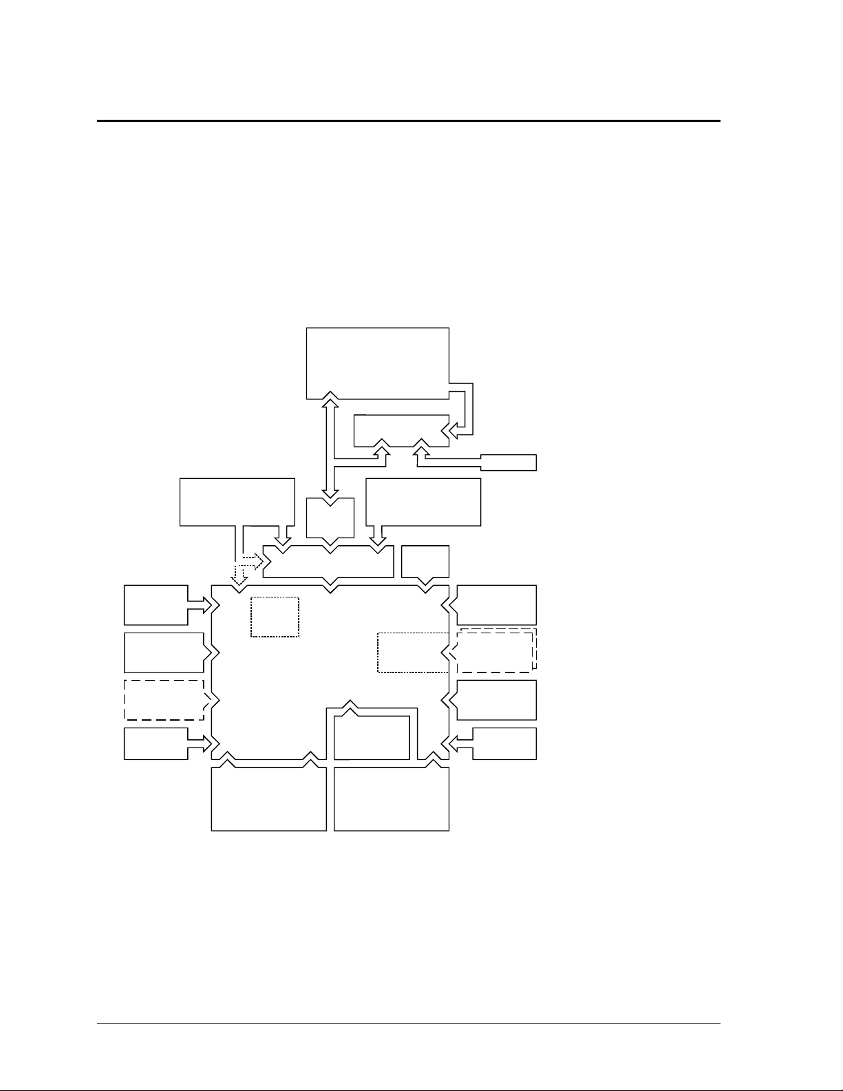
The following figure shows the connections among the replaceable electrical modules. As a substitute
for a functional block diagram, see the table on page 1-15—it lists the roles that the replaceable
modules play in each of the functional subsystems.
PCMCIA
Cards
CPU
Module
Audio Jack
PCA
DC-DC
PCA
Main
Battery
Keyboard
(pointing stick)
RAM
Board
LVDS
PCA
VGA PCA
LCD Module
Top Case
(touch pad support)
Motherboard
PCA
BIOS
IC
Hard Disk
Drive
Fan
Speaker Speaker
Plug-In
Module
or Battery
IR
PCA
Inverter PCA
(microphone)
LED Strip
PCMCIA
Socket
Figure 1-4. Replaceable Module Diagram
The BIOS IC is not
removable on the
OmniBook 4150 Series.
Two RAM slots are
available on the
OmniBook 4150 Series.
The power switch and lid
switch are contained on
the motherboard.
All external connections
(except IR and audio) are
made to the motherboard.
Keyboard cable connects to
VGA PCA (OmniBook 4100) or
motherboard (OmniBook 4150
Series).
LVDS PCA is not present in the
OmniBook 4150B.

HP OmniBook 4100/4150 Product Information 1-15
Table 1-13. Functional Structure
Bootup
CPU module
Motherboard
BIOS IC
Floppy disk module
Hard disk drive
Main processor (MMO).
Primary system circuitry.
Code for basic system functions (part of motherboard on OB 4150).
First source of disk-based startup code.
Second source of disk-based startup code.
Processor
CPU module
Motherboard
Main processor, numeric data processor, L1 and L2 cache.
Primary system circuitry.
Memory
Motherboard
RAM board
VGA PCA
No onboard RAM (OB 4150), or first 32 MB of RAM (OB 4100).
Changeable RAM (1 slot on OB 4100, 2 slots on OB 4150).
Video RAM.
Power
Battery
Motherboard
DC-DC PCA
AC adapter
Power storage.
AC adapter socket, power switch, lid switch, system-off switch, power
supply.
Power control circuitry.
AC-to-dc converter.
Display
Motherboard
LCD module
Inverter PCA
LVDS PCA
VGA PCA
PCMCIA/zoomed video controller.
Display output, backlight.
Power converter for backlight.
Display drivers, LVDS processing (OB 4100/4150†).
Display/graphics controller, video RAM (OB 4150B: LVDS processing).
Hard disk
Motherboard
Hard disk drive
Hard disk controller.
Hard disk mechanism.
Floppy drive
Motherboard
Floppy disk module
I/O controller, floppy connector.
Floppy disk mechanism.
Keyboard
Motherboard
BIOS IC
Keyboard
Keyboard controller.
Keyboard BIOS (part of motherboard on OB 4150).
Key switches.
Pointer
Motherboard
BIOS IC
Keyboard
Top case
Keyboard controller, pointing stick controller (PS/2 output).
Keyboard BIOS (part of motherboard on OB 4150).
Pointing stick sensor.
Touch pad sensor, controller (PS/2 output).
Audio
Motherboard
VGA PCA
Audio jack PCA
Inverter PCA
Speakers
Audio controller (OB 4100/4150B), audio decoder, speaker amplifier,
headphone amplifier, zoomed video controller, mute switch.
Audio controller (OB 4150†).
External audio jacks.
Microphone.
Speakers.
Status
Motherboard
LED strip cable
VGA PCA
Keyboard controller, plus keyboard LEDs (OB 4150).
Main LEDs.
Keyboard LEDs (OB 4100).
Serial
Motherboard I/O controller, serial connector.
Parallel
Motherboard I/O controller, parallel connector.
Infrared
Motherboard
IR PCA
I/O controller.
Infrared transmitter/receiver.
PS/2 port
Motherboard Keyboard controller, PS/2 connector.
USB
Motherboard Bus controller (South Bridge), USB connector.
Docking port
Motherboard Docking logic, docking connector.
PCMCIA
Motherboard
PCMCIA socket
PCMCIA controller.
PCMCIA connectors.
† Models called 4150† in this manual have no marking in the serial number, whereas models called 4150B
have 4150 B after the serial number.


HP OmniBook 4100/4150 Removal and Replacement 2-1
2
Removal and Replacement
This chapter tells you how to remove and replace the following components and assemblies. The ones
marked by
• are user-replaceable.
Table 2-1. Removal Cross-Reference
Air vent cover (table on page 2-33).
Audio jack cover (table on page 2-33).
Audio jack PCA (table on page 2-33).
• Battery (page 2-3).
BIOS IC (page 2-28).
Bottom case (page 2-19).
Cable holder (table on page 2-31).
CPU bottom plate (table on page 2-33).
CPU module (page 2-13).
CPU top plate (table on page 2-33).
DC-DC PCA (table on page 2-33).
Display bezel (table on page 2-31).
Display case (table on page 2-31).
Display latch (table on page 2-31).
• Docking door (table on page 2-8).
End cap (table on page 2-31).
Fan (table on page 2-33).
• Foot (table on page 2-8).
Frame (table on page 2-33).
• Hard disk drive (page 2-5).
Heatsink parts (table on page 2-33).
Hinge (table on page 2-31).
• Hinge cover (table on page 2-8).
Inverter PCA (table on page 2-31).
• I/O door (table on page 2-8).
IR PCA (table on page 2-33).
Keyboard (page 2-9).
LCD brackets (table on page 2-31).
LCD flex cable (table on page 2-31).
LCD module (page 2-13).
LCD shield (table on page 2-31).
LED strip cable (table on page 2-31).
LVDS PCA (table on page 2-33).
Module latch (table on page 2-33).
Motherboard (page 2-19).
PCMCIA socket (table on page 2-33).
• Plug-in module (page 2-3).
• RAM board (page 2-4).
• RAM/BIOS cover (table on page 2-8).
Speaker cover (table on page 2-33).
Speaker (table on page 2-33).
Spring, grounding (table on page 2-33).
Strip cover (table on page 2-32).
Top case (page 2-16).
• VGA connector cover (table on page 2-8).
VGA PCA (table on page 2-33).
Caution
Always provide proper grounding when performing repairs. Without proper
grounding, an electrostatic discharge may damage the OmniBook and its
components.

2-2 Removal and Replacement HP OmniBook 4100/4150
Notes
Reassembly steps are the reverse of the removal steps. Reassembly notes are included at the
end of each section below.
Symbols like this throughout this chapter show approximate full-size screw outlines. You
can use them to verify the sizes of screws before you install them. Installing a wrong-size screw
can damage the unit. (The symbol at the left represents an M2.5×5mm T-head screw.)
Table 2-2. Required Equipment
• Small Phillips screwdriver, preferably magnetized.
• 5 mm hex driver.
• Pointed knife or probe.
• Small flat-blade screwdriver.
• IC (PLCC) removal tool (similar to OK Industries EX-5).
• OmniBook 4150† CPU removal tool (HP part number T-335665).
Table 2-3. Recommended Screw Torques
Screw Thread Size Torque (kgf•cm) Torque (lbf•in)
M2 1.3 – 1.8 1.1 – 1.5
M2.5 (4–5 mm long) 3.0 – 3.5 2.6 – 3.0
M2.5 (16–19 mm long) 2.5 – 3.0 2.2 – 2.6
M3 3.0 – 3.5 2.6 – 3.0

HP OmniBook 4100/4150 Removal and Replacement 2-3
Removing the Battery or Plug-In Module
(User-Replaceable)
Required Equipment
• None.
Removal Procedure
1. Unplug the ac adapter, if present.
2. Slide forward the module latch slider on the corner next to the module, then swing back the latch
to loosen the module.
3. Pull out the module.
4. Slide the latch back into the case.
Figure 2-1. Removing the Battery or Plug-In Module
Reassembly Notes
• Important: You must slide the latch forward before you can insert a module.
• You can install a battery in either bay. Any other type of module must be installed in the left bay.

2-4 Removal and Replacement HP OmniBook 4100/4150
Removing a RAM Board
(User-Replaceable)
The OmniBook 4100 has 32 MB of RAM on the motherboard and has one RAM slot for installing
additional RAM. The OmniBook 4150 Series has no RAM on the motherboard and has two RAM
slots for installing RAM.
Table 2-4. RAM Board Replacement Part Numbers
Description Part Number Exchange OmniBook
Part Number 4150B 4150† 4100
RAM board, 32-MB SDRAM (66 MHz) 1818-7413 F1456-69001
••
RAM board, 64-MB SDRAM (66 MHz) 1818-7414 F1457-69001
••
RAM board, 128-MB SDRAM (66 MHz) 1818-7549 F1622-69001
••
RAM board, 32-MB SDRAM (100 MHz) 1818-7950
•••
RAM board, 64-MB SDRAM (100 MHz) 1818-7951
•••
RAM board, 128-MB SDRAM (100 MHz) 1818-7952
•••
† Models called 4150† in this manual have no marking in the serial number, whereas models called
4150B have 4150 B after the serial number.
Caution
Handle the RAM board only by its edges and provide proper grounding. Otherwise, you may
damage the board due to electrostatic discharge.
Required Equipment
• Small Phillips screwdriver.
Removal Procedure
1. Unplug the ac adapter, if present, and remove the battery.
2. Turn the unit bottom side up, then remove the two screws from the RAM/BIOS cover and remove
the cover.
3. Release the two latches at the sides of the RAM board, so the free edge of the board pops up.
4. Pull the board out of the connector.
Figure 2-2. Removing a RAM Board
Note:
OmniBook 4100 shown. For the
OmniBook 4150 Series, there are
two RAM slots (with no RAM built
into the motherboard).

HP OmniBook 4100/4150 Removal and Replacement 2-5
Reassembly Notes
• Insert the RAM board into the connector at about a 30° angle until it is fully inserted. Then press
down at both sides until both latches snap closed.
Removing the Hard Disk Drive
(User-Replaceable)
Table 2-5. Hard Disk Drive Replacement Part Numbers
Description Part Number Exchange OmniBook
Part Number 4150B 4150† 4100
Drive, hard disk (4.0GB, 12.7mm, IBM) 0950-2671 F1386-69100
•
Drive, hard disk (4.0GB, 12.7mm, Toshiba) 0950-2865 F1386-69101
•
Drive, hard disk (4.3GB, 9.5mm, IBM) 0950-3409 F1711-69100
••
Drive, hard disk (4.8GB, 9.5mm, IBM) * 0950-3611 F1711-69102
•••
Drive, hard disk (6.4GB, 9.5mm, IBM) * 0950-3442 F1711-69101
•••
Drive, hard disk (6.4GB, 12.7mm, IBM) 0950-2785 F1475-69100
••
Drive, hard disk (6.4GB, 8.4mm, Toshiba) 0950-3675 F1475-69102
•••
Drive, hard disk (6.4GB, 12.7mm, Toshiba) 0950-3397 F1475-69101
••
Drive, hard disk (10.1 GB, 12.5mm, IBM) * 0950-3443 F1744-69101
••
* These hard drives are the preferred drives at the time of publication. Drives shipped in units are
subject to change without notice. For current information about preferred and approved drives for
these products, see the latest version of service note HDD-01.
† Models called 4150† in this manual have no marking in the serial number, whereas models called
4150B have 4150 B after the serial number.
Required Equipment
• Small Phillips screwdriver.
• Small flat-blade screwdriver.
Removal Procedure
1. Unplug the ac adapter, if present, and remove the battery.
2. Turn the unit bottom side up.
3. Remove the hard drive screw from the bottom case.
4. Pull out the hard drive by its plastic tab.
Figure 2-3. Removing the Hard Disk Drive
Screw, M3×4mm
2-6 Removal and Replacement HP OmniBook 4100/4150
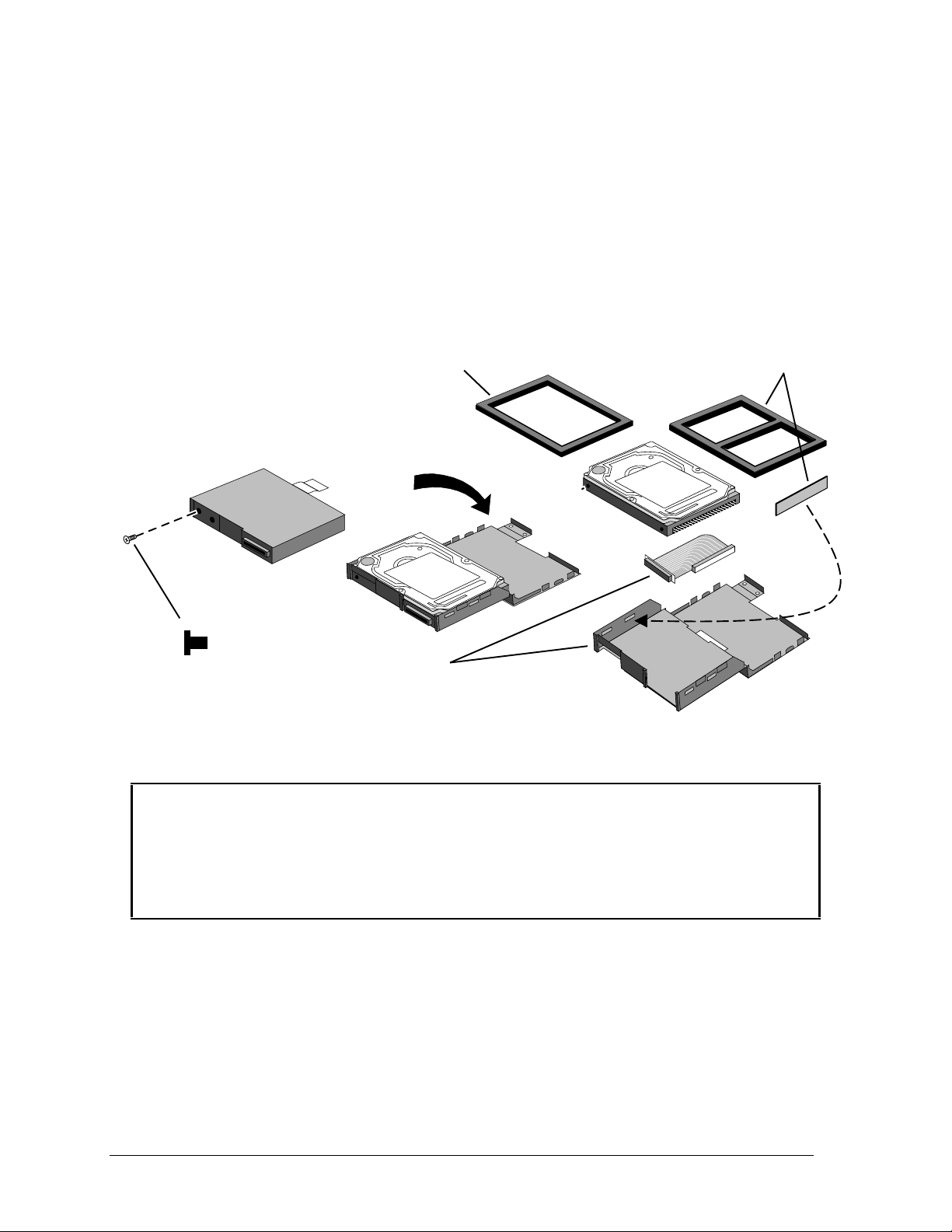
5. If you are installing a new hard drive that does not have a cover, you can remove the cover parts
from the old hard drive:
• Remove the screw from the case, then pry open the flap. If necessary, use a flat-blade
screwdriver
• Use a flat-blade screwdriver to pry open the snaps at the ends of the case, then open the
connector-side of the case.
• Pry out the corner next to the connector, then lift out the connector and hard drive together.
• Unplug the internal connector and cable from the hard drive.
Figure 2-4. Installing a Hard Drive in the Cover
Reassembly Notes
Caution
• Do not cover the vent hole in the top surface of the hard drive or in the case. If you cover the
hole, the hard drive could fail prematurely.
• If you install a 9.5-mm hard drive in the case, make sure you install the spacer on top of the
drive. If you install an 8.4-mm hard drive, make sure you stick the end spacer on the case and
install the top spacer on top of the drive.
• Pry out the connector corner of the case and insert the external connector and hard drive at the
same time. The connector seats in the lower part of the opening in the case.
• Secure the two tabs on the screw flap by inserting the corner tab last, while prying out the nearby
corner of the case.
• When you install the battery module, be sure the plastic tab on the hard drive case lays folds up
against the front of the case.
Screw, M3×4mm
HDD cover kit
Spacers for 8.4mm HDD
(see Caution)
Spacer for 9.5mm HDD
(see Caution)

HP OmniBook 4100/4150 Removal and Replacement 2-7
Important
• If you are installing a new hard drive, create a Hibernate partition on the drive before loading
any software—see the steps below.
Creating a Hibernate Partition – OmniBook 4100
1. If you do not have an OmniBook Recovery CD and internal CD-ROM (or DVD) module for the
computer you are repairing, create a Support Utility floppy disk now.
After inserting a formatted floppy disk in the floppy drive, do one of the following:
On an OmniBook 4100 with a Spring-98 factory software installation, click Start, Programs,
OmniBook, Create Support Utility Disk.
On any computer that has a CD-ROM drive, run makesupp from the
\Omnibook\Drivers\Hputils directory on the OmniBook 4100 Recovery CD.
2. Insert the Recovery CD in the CD-ROM drive—or insert the Support Utility disk in the floppy
drive.
3. Reboot the computer. If you are using the Recovery CD, press ESC during reboot to cancel the
OmniBook screen, ESC to display the boot-device menu, then select the CD-ROM drive as the
boot device.
4. When prompted, select “Create Hibernate Partition.”
We recommend that you create a partition the same as the default option.
Creating a Hibernate Partition—OmniBook 4150 Series
1. Plug in the ac adapter.
2. Insert the Recovery CD in the CD-ROM drive.
3. Shut down and restart the computer—when you see the HP logo, press ESC two times.
4. Select the CD-ROM drive as the boot device.
5. When the Recovery CD dialog box appears, follow the displayed instructions. Accept the
recommended partition size. If you install the factory software, the recovery process can take up
to 10 minutes.
If you want to create the Hibernate partition without installing the factory software, click
Advanced and select the option to not install the operating system. If you intend to install
Windows NT, you should choose the FAT16 option or the Hibernate-only option.
Note: If, instead, you see an MS-DOS menu of options, select “Recover...” to create the
Hibernate partition and install the factory software, which can take up to 60 minutes. Or select
“Create Hibernate Partition” to not install the software. Accept the recommended partition size.
6. When prompted to reboot the computer, press CTRL+ALT+DEL and follow any displayed
instructions.

2-8 Removal and Replacement HP OmniBook 4100/4150
Replacing Small Parts
(User-Replaceable)
The following small parts are user-replaceable.
Table 2-6. Replacing Small Parts (User-Replaceable)
Part Replacement Procedure
Docking Doors
Open each door and flex the door until one side tab releases. To replace, see the
picture on page 2-28.
Feet
Insert a small flat-blade screwdriver under the foot and pry it loose. To replace, firmly
press the adhesive side of the foot into the recess.
Hinge Cover, Left
With the display lid fully open, push back on the bottom edge of the hinge cover until
it unsnaps, then work it loose and lift it off. To install, make sure the front and back
tabs snap into the case.
Hinge Cover, Right
With the display lid closed, push in the bottom of the hinge cover until it unsnaps,
then work it loose and lift it off. To install, make sure the front and back tabs snap
into the case.
I/O Door
With the door closed, insert a small flat-blade screwdriver behind the door from
below. Flex the door until one side tab releases. It helps to press in lightly on the
ends of the door. To install, keep the icons on the door toward the top.
Pointing Stick Cap
Pull the cap off the pointing stick.
RAM/BIOS Cover
On the bottom of the unit, remove the two screws from the RAM/BIOS cover and
remove the cover.
VGA Connector Cover
With the display closed, push up on the connector cover and down on the bottom
case until the lower tabs release. To install, insert the top tabs into the strip cover,
then push up on the cover and down on the bottom case until you can insert the
lower tabs.
 Loading...