


HP Omnibook XE3
(AMD CPU Version: Technology Codes GE and GD)
Service Manual

Notice
In a continuing effort to improve the quality of our products, technical and environmental information in this document is subject to change without notice.
This manual and any examples contained herein are provided “as is” and are subject to change without notice. Hewlett-Packard Company makes no warranty of any kind with regard to this manual, including, but not limited to, the implied warranties of merchantability and fitness for a particular purpose. Hewlett-Packard Co. shall not be liable for any errors or for incidental or consequential damages in connection with the furnishing, performance, or use of this manual or the examples herein.
Consumer transactions in Australia and the United Kingdom: The above disclaimers and limitations shall not apply to Consumer transactions in Australia and the United Kingdom and shall not affect the statutory rights of Consumers.
© Copyright Hewlett-Packard Company 2000–2001. All rights reserved. Reproduction, adaptation, or translation of this manual is prohibited without prior written permission of Hewlett-Packard Company, except as allowed under the copyright laws.
The programs that control this product are copyrighted and all rights are reserved. Reproduction, adaptation, or translation of those programs without prior written permission of Hewlett-Packard Co. is also prohibited.
Portions of the programs that control this product may also be copyrighted by Microsoft Corporation, Phoenix Technologies Ltd., ESS, Accton, Trident Microsystems Incorporated, Acer Laboratories Incorporated, and Adobe Systems Incorporated. See the individual programs for additional copyright notices.
This product incorporates copyright protection technology that is protected by method claims of certain U.S. patents and other intellectual property rights owned by Macrovision Corporation and other rights owners. Use of this copyright protection technology must be authorized by Macrovision Corporation and is intended for home and other limited viewing uses only unless otherwise authorized by Macrovision Corporation. Reverse engineering or disassembly is prohibited.
Microsoft®, MS-DOS®, and Windows® are U.S. registered trademarks of Microsoft Corporation. TrackPoint™ is a U.S. trademark of International Business Machines. Adobe® and Acrobat® are trademarks of Adobe Systems Incorporated.
All certifications may not be completed at product introduction. Check with your HP reseller for certification status.
This equipment is subject to FCC rules. It will comply with the appropriate FCC rules before final delivery to the buyer.
Hewlett-Packard Company
Mobile Computing Division
19310 Pruneridge Ave.
Cupertino, CA 95014, U.S.A.
Edition History
Edition 1 |
......................... August 2000 |
Edition 2 .................... |
November 2001 |
ii |
HP Omnibook XE3 (Technology Codes GE and GD) |

Contents
Product Information ...................................................................................................... |
1-1 |
Technology Codes ........................................................................................................................ |
1-2 |
Features......................................................................................................................................... |
1-3 |
Operation ...................................................................................................................................... |
1-6 |
Turning the Notebook On and Off......................................................................................... |
1-6 |
Checking the Notebook’s Status............................................................................................ |
1-7 |
Using Fn Hot Keys................................................................................................................. |
1-9 |
Resetting the Notebook........................................................................................................ |
1-10 |
Using the CD/DVD Player (selected models) ..................................................................... |
1-11 |
Specifications.............................................................................................................................. |
1-12 |
Hardware Specifications ...................................................................................................... |
1-12 |
Internal Design............................................................................................................................ |
1-15 |
Removal and Replacement ............................................................................................ |
2-1 |
Disassembly Flowchart................................................................................................................. |
2-2 |
Removing the Battery (User-Replaceable) ................................................................................... |
2-4 |
Removing an SDRAM Module (User-Replaceable) .................................................................... |
2-5 |
Removing the Mini-PCI PCA (selected models) (User-Replaceable).......................................... |
2-7 |
Replacing Small Parts (User-Replaceable)................................................................................... |
2-9 |
Removing the Keyboard Cover (HP Authorized Service Providers Only)................................. |
2-10 |
Removing the Keyboard (HP Authorized Service Providers Only) ........................................... |
2-12 |
Removing the Hard Disk Drive (HP Authorized Service Providers Only) ................................ |
2-14 |
Removing the Display Assembly (HP Authorized Service Providers Only).............................. |
2-18 |
Removing the Top Case (HP Authorized Service Providers Only)............................................ |
2-22 |
Removing the CD Player PCA (selected models) (HP Authorized Service Providers Only) .... |
2-24 |
Removing the Hinge Saddle Set (HP Authorized Service Providers Only) ............................... |
2-25 |
Removing the Video PCA (HP Authorized Service Providers Only) ........................................ |
2-27 |
Removing the Heatsink Assembly (with Fan) (HP Authorized Service Providers Only) .......... |
2-29 |
Removing the CPU Module (HP Authorized Service Providers Only)...................................... |
2-30 |
Removing the Floppy Disk Drive (HP Authorized Service Providers Only) ............................. |
2-32 |
Removing the CD/DVD Drive (HP Authorized Service Providers Only) ................................. |
2-34 |
Removing the Motherboard or Bottom Case (HP Authorized Service Providers Only) ............ |
2-35 |
Reinstalling the Motherboard .............................................................................................. |
2-37 |
Replacing the Bottom Case.................................................................................................. |
2-38 |
Removing Notebook Components (HP Authorized Service Providers Only)............................ |
2-40 |
Troubleshooting and Diagnostics.................................................................................. |
3-1 |
Troubleshooting............................................................................................................................ |
3-2 |
Checking for Customer Abuse............................................................................................... |
3-3 |
Troubleshooting the Problem................................................................................................. |
3-4 |
Verifying the Repair .............................................................................................................. |
3-4 |
Suggestions for Troubleshooting ........................................................................................... |
3-5 |
Diagnostic Tools......................................................................................................................... |
3-22 |
e-DiagTools Diagnostic Program ........................................................................................ |
3-22 |
Power-On Self-Test ............................................................................................................. |
3-28 |
Sycard PCCtest 450/460 CardBus Card (Optional)............................................................. |
3-31 |
Desktop and Windows Management Interfaces (DMI/WMI).............................................. |
3-32 |
BIOS Setup Utility............................................................................................................... |
3-33 |
HP Omnibook XE3 (Technology Codes GE and GD) |
iii |

Replaceable Parts ........................................................................................................... |
4-1 |
Reference Information ................................................................................................... |
5-1 |
Password Removal Policy ............................................................................................................. |
5-1 |
Hewlett-Packard Display Quality Statement ................................................................................. |
5-2 |
Figures
Figure 1-1. Top/Right View ................................................................................................................. |
1-3 |
Figure 1-2. Front View ......................................................................................................................... |
1-4 |
Figure 1-3. Rear/Left View .................................................................................................................. |
1-4 |
Figure 1-4. Bottom View...................................................................................................................... |
1-5 |
Figure 1-5. Status Lights ...................................................................................................................... |
1-7 |
Figure 1-6. Resetting the Notebook.................................................................................................... |
1-10 |
Figure 1-7. Multimedia Buttons ......................................................................................................... |
1-11 |
Figure 1-8. Replaceable Module Diagram ......................................................................................... |
1-15 |
Figure 2-1. Disassembly Flow.............................................................................................................. |
2-2 |
Figure 2-2. Removing the Battery ........................................................................................................ |
2-4 |
Figure 2-3. Removing the SDRAM Cover........................................................................................... |
2-5 |
Figure 2-4. Removing an SDRAM Module ......................................................................................... |
2-6 |
Figure 2-5. Removing the Mini-PCI PCA............................................................................................ |
2-8 |
Figure 2-6. Removing the Keyboard Cover Retaining Screws .......................................................... |
2-10 |
Figure 2-7. Removing the Keyboard Cover ....................................................................................... |
2-11 |
Figure 2-8. Loosening the Keyboard Retaining Screws ..................................................................... |
2-12 |
Figure 2-9. Disconnecting the Keyboard Cable ................................................................................. |
2-13 |
Figure 2-10. Removing the Hard Disk Drive ..................................................................................... |
2-15 |
Figure 2-11. Removing the Hard Disk Carrier ................................................................................... |
2-15 |
Figure 2-12. Removing the Display ................................................................................................... |
2-19 |
Figure 2-13. Video PCA DIP Switches.............................................................................................. |
2-21 |
Figure 2-14. Removing the Top Case Retaining Screws.................................................................... |
2-22 |
Figure 2-15. Removing the Top Case................................................................................................. |
2-23 |
Figure 2-16. Removing the CD Player PCA ...................................................................................... |
2-24 |
Figure 2-17. Removing the Hinge Saddle Retaining Screws ............................................................. |
2-25 |
Figure 2-18. Removing the Hinge Saddle .......................................................................................... |
2-26 |
Figure 2-19. Removing the Video PCA ............................................................................................. |
2-28 |
Figure 2-20. Removing the Heatsink Assembly................................................................................. |
2-29 |
Figure 2-21. Removing the CPU Module........................................................................................... |
2-31 |
Figure 2-22. Removing the Floppy Disk Drive .................................................................................. |
2-33 |
Figure 2-23. Removing the CD/DVD Drive ...................................................................................... |
2-34 |
Figure 2-24. Removing the Motherboard ........................................................................................... |
2-36 |
Figure 2-25. Installing the PCMCIA Doors ....................................................................................... |
2-38 |
Figure 2-26. Example of Serial Number Label .................................................................................. |
2-39 |
Figure 3-1. Basic Troubleshooting Steps ............................................................................................. |
3-2 |
Figure 3-2. e-DiagTools Screens — Basic and Advanced ................................................................. |
3-22 |
Figure 3-3. Serial and Parallel Loopback Connectors ........................................................................ |
3-24 |
Figure 4-1. Exploded View .................................................................................................................. |
4-2 |
iv |
HP Omnibook XE3 (Technology Codes GE and GD) |

Tables
Table 1-1. Omnibook XE3 Series Models........................................................................................... |
1-1 |
Table 1-2. Activating Power Modes.................................................................................................... |
1-6 |
Table 1-3. Status Lights....................................................................................................................... |
1-8 |
Table 1-4. Fn Hot Keys ....................................................................................................................... |
1-9 |
Table 1-5. XE3 Series Hardware Specifications ............................................................................... |
1-12 |
Table 1-6. XE3 Series Accessories ................................................................................................... |
1-14 |
Table 1-7. Functional Structure ......................................................................................................... |
1-16 |
Table 2-1. Removal Cross-Reference.................................................................................................. |
2-1 |
Table 2-2. Required Equipment........................................................................................................... |
2-3 |
Table 2-3. Recommended Screw Torques........................................................................................... |
2-3 |
Table 2-4. SDRAM Module Replacement Part Numbers ................................................................... |
2-5 |
Table 2-5. Mini-PCI PCA Replacement Part Numbers....................................................................... |
2-7 |
Table 2-6. Replacing Small Parts (User-Replaceable) ........................................................................ |
2-9 |
Table 2-7. Hard Disk Drive Replacement Part Numbers .................................................................. |
2-14 |
Table 2-8. Motherboard Video DIP Switch Settings for Technology Code GE Models .................. |
2-20 |
Table 2-9. Motherboard Video DIP Switch Settings for Technology Code GD Models.................. |
2-20 |
Table 2-10. CPU Module Replacement Part Numbers...................................................................... |
2-30 |
Table 2-11. Removing Notebook Components ................................................................................. |
2-40 |
Table 3-1. Scope of Diagnostic Tools ................................................................................................. |
3-5 |
Table 3-2. Troubleshooting Suggestions ............................................................................................. |
3-6 |
Table 3-3. e-DiagTools Error Codes ................................................................................................. |
3-25 |
Table 3-4. POST Terminal-Error Beep Codes .................................................................................. |
3-28 |
Table 3-5. POST Messages ............................................................................................................... |
3-29 |
Table 3-6. Sycard PCCtest Commands ............................................................................................. |
3-31 |
Table 3-7. BIOS Setup Menus and Parameters ................................................................................. |
3-33 |
Table 4-1. Replaceable Parts for Technology Code GE Models......................................................... |
4-3 |
Table 4-2. Replaceable Parts for Technology Code GD Models ........................................................ |
4-5 |
Table 4-3. Accessory Replaceable Parts.............................................................................................. |
4-7 |
Table 4-4. Part Number Reference ...................................................................................................... |
4-8 |
Table 5-1. XE3 TFT LCD Guidelines (13.3/14.1/15.0-in XGA, 15.0-in SXGA+) ............................ |
5-3 |
HP Omnibook XE3 (Technology Codes GE and GD) |
v |

Introduction
This manual provides reference information for servicing HP Omnibook XE3 notebook PCs. It is for use by HP-authorized service personnel while installing, servicing, and repairing these products.
The manual is designed as a self-paced guide that will train you to install, configure, and repair XE3 notebooks. The manual is self-contained, so you can follow it without having equipment available.
The following table lists other sources of information about the notebook and related products.
Source |
Address or Number |
Comments |
HP Notebook Web Site |
http://www.hp.com/notebooks |
|
|
(European mirror: |
|
|
http://www.europe.hp.com/notebooks) |
|
HP Partnership Web |
http://partner.americas.hp.com |
Restricted to Authorized Resellers |
|
|
only. |
HP Asia Pacific Channel |
http://www.hp.com.au |
Restricted to DPSP Partners only. |
Support Centre for DPSP |
|
|
Partners |
|
|
HP/MCD Web Site |
http://www.mcd.hp.com |
HP’s internal web site for division |
|
|
information. |
America Online |
Keyword: HP |
Call (800) 827-6364 for membership |
|
|
within the US. |
CompuServe |
GO HP |
Call (800) 524-3388 for membership |
|
|
within the US. |
HP Support Assist CD |
(800) 457-1762 |
US and Canada. |
|
(801) 431-1587 |
Outside US and Canada. |
Microsoft Windows manual |
|
Information about Windows operating |
|
|
system. |
Microsoft Web |
http://www.microsoft.com |
Information and updates for Windows |
|
|
operating systems. |
vi |
HP Omnibook XE3 (Technology Codes GE and GD) |

1
Product Information
The Omnibook XE3 series is HP’s value all-in-one business notebook computer, targeted at smallto medium-sized businesses (SMBs). It combines affordability, value, ease-of-use, and quality in a convenient package that integrates easily into any SMB environment at a wide range of prices. It also incorporates several new technologies and an enhanced industrial design for greater ease-of-use, quality, and reliability.
The products described in this service manual may have either of two technology codes—GE or GD—as listed in the following table. These codes determine the service parts needed for that model— see “Technology Codes“ on page 1-2.
Table 1-1. Omnibook XE3 Series Models
Product |
CPU |
Display/color |
Hard |
Standard |
CD/DVD |
Multimedia |
LAN |
Battery 2 |
OS 3 |
Tech. |
|
|
|
Drive |
SDRAM |
drive 1 |
buttons/ |
|
|
|
Code |
|
|
|
|
|
|
status panel |
|
|
|
|
F2407M |
Athlon 1 GHz |
15.0” XGA/silver |
20 GB |
256 MB |
Combo |
Yes |
Y |
9 Li-Ion |
ME |
GD |
F2409 |
Duron 800 MHz |
13.3-in XGA/blue |
10 GB |
128 MB |
CD (24X) |
No 5 |
N |
NiMh |
W98 |
GD |
F2410 |
Athlon 1 GHz |
13.3-in XGA/blue |
10 GB |
128 MB |
CD (24X) |
No 5 |
N |
NiMh |
W98 |
GD |
F2411 |
Duron 800 MHz |
13.3-in XGA/blue |
10 GB |
128 MB |
CD (24X) |
No 5 |
N |
NiMh |
W98 |
GD |
F2412 |
Duron 800 MHz |
13.3-in XGA/blue |
10 GB |
128 MB |
CD (24X) |
No 5 |
N |
NiMh |
W98 |
GD |
F2418M |
Duron 850 MHz |
14.1-in XGA/silver |
20 GB |
128 MB |
DVD (8X) |
Yes |
Y |
6 Li-Ion |
ME |
GD |
F2419M |
Athlon 900 MHz |
15.0-in XGA/silver |
20 GB |
256 MB |
DVD (8X) |
Yes |
Y |
9 Li-Ion |
ME |
GD |
F2420M |
Athlon 1 GHz |
15.0-in XGA/silver |
30 GB |
256 MB |
Combo |
Yes |
Y |
9 Li-Ion |
ME |
GD |
|
|
|
|
|
|
|
|
|
|
|
F3779 |
Duron 800 MHz |
13.3-in XGA/cole gray |
10 GB |
128 MB |
CD (24X) |
No 5 |
N |
NiMh |
W98 |
GD |
F3780 |
Athlon 900 MHz |
14.1-in XGA/cole gray |
20 GB |
128 MB |
DVD (8X) |
Yes |
Y |
9 Li-Ion |
W98 |
GD |
F3781 |
Athlon 900 MHz |
14.1-in XGA/cole gray |
20 GB |
128 MB |
Combo |
Yes |
Y |
9 Li-Ion |
W98 |
GD |
|
|
|
|
|
|
|
|
|
|
|
F3783M |
Duron 850 MHz |
14.1-in XGA/silver |
20 GB |
256 MB |
DVD (8X) |
Yes |
Y |
6 Li-Ion |
ME/works |
GD |
F3784M |
Duron 850 MHz |
14.1-in XGA/silver |
20 GB |
256 MB |
Combo |
Yes |
Y |
6 Li-Ion |
ME/works |
GD |
F3865M |
Duron 850 MHz |
14.1-in XGA/silver |
20 GB |
128 MB |
DVD (8X) |
Yes |
Y |
6 Li-Ion |
ME/works |
GD |
|
|
|
|
|
|
|
|
|
|
|
F3886HT |
Duron 900 MHz |
14.1-in XGA/silver |
20 GB |
256 MB |
Combo |
Yes |
Y |
9 Li-Ion |
XP Home |
GE |
F3924H |
Athlon 900 MHz |
14.1-in XGA/silver |
20 GB |
256 MB |
Combo |
Yes |
Y |
9 Li-Ion |
XP Home |
GE |
F3927H |
Athlon 1 GHz |
15.0-in XGA/silver |
30 GB |
256 MB |
Combo |
Yes |
Y |
9 Li-Ion |
XP Home |
GE |
|
|
|
|
|
|
|
|
|
|
|
F3928H |
Athlon 950 MHz |
14.1-in XGA/silver |
20 GB |
2x128 MB 4 |
DVD (8X) |
Yes |
Y |
9 Li-Ion |
XP Home |
GE |
F3929H |
Athlon 1 GHz |
15.0-in XGA/silver |
20 GB |
2x256 MB |
Combo |
Yes |
Y |
9 Li-Ion |
XP Home |
GE |
F3930H |
Athlon 1.1 GHz |
15.0-in SXGA+/silver |
30 GB |
2x256 MB |
Combo |
Yes |
Y |
9 Li-Ion |
XP Home |
GE |
|
|
|
|
|
|
|
|
|
|
|
F3931H |
Duron 900 MHz |
14.1-in XGA/silver |
10 GB |
256 MB |
DVD (8X) |
No 5 |
Y |
9 Li-Ion |
XP Home |
GE |
F3933H |
Athlon 950 MHz |
14.1-in XGA/silver |
20 GB |
2x128 MB 4 |
Combo |
Yes |
Y |
9 Li-Ion |
XP Home |
GE |
F3978AV |
BTCO |
BTCO |
BTCO |
BTCO |
BTCO |
Yes |
Y |
BTCO |
XP Home |
GE |
|
|
|
|
|
|
|
|
|
|
|
F3980AV |
BTCO |
BTCO |
BTCO |
BTCO |
BTCO |
No 5 |
Y |
BTCO |
XP Home |
GE |
HP Omnibook XE3 (Technology Codes GE and GD) |
Product Information |
1-1 |

Product |
CPU |
Display/color |
Hard |
Standard |
CD/DVD |
|
Multimedia |
LAN |
Battery 2 |
OS 3 |
|
Tech. |
||
|
|
|
|
|
Drive |
SDRAM |
drive 1 |
|
buttons/ |
|
|
|
|
Code |
|
|
|
|
|
|
|
|
|
status panel |
|
|
|
|
|
F4307H |
Duron 900 MHz |
14.1-in XGA/silver |
20 GB |
128 MB |
Combo |
|
Yes |
Y |
NiMH |
XP Home |
|
GE |
||
F4308H |
Athlon 900 MHz |
14.1-in XGA/silver |
20 GB |
256 MB |
Combo |
|
Yes |
Y |
NiMH |
XP Home |
|
GE |
||
F4309H |
Athlon 1 GHz |
15.0-in SXGA+/silver |
30 GB |
256 MB |
Combo |
|
Yes |
Y |
9 Li-Ion |
XP Home |
|
GE |
||
|
|
|
|
|
|
|
|
|
|
|
|
|
|
|
This table lists only base product configurations—custom configurations are not included. |
|
|
|
|
|
|
||||||||
All models include 56K modem. |
|
|
|
|
|
|
|
|
|
|
||||
LAN supports Ethernet 10Base-T (10 Mbps) and 100Base-T (100 Mbps). |
|
|
|
|
|
|
|
|
||||||
BTCO = Built to Customer Order. |
|
|
|
|
|
|
|
|
|
|
||||
1 |
Combo optical drive = DVD + CD-RW. |
|
|
|
|
|
|
|
|
|
|
|||
2 |
Battery = 6- or 9-cell Li-Ion or NiMH. |
|
|
|
|
|
|
|
|
|
|
|||
3 |
OS = Windows XP Home Edition, Windows ME, or Windows 98. |
|
|
|
|
|
|
|
|
|||||
4 |
Two 128-MB modules instead of one 256-MB module. |
|
|
|
|
|
|
|
|
|
||||
5 |
“Defeatured” SKUs have no multimedia player buttons or LCD status panel. |
|
|
|
|
|
|
|||||||
|
|
|
|
|
|
|
|
|
|
|
|
|
|
|
|
|
|
|
|
|
|
|
|
|
|
|
|
|
|
Technology Codes
HP does not change the name of a product every time the product’s technology changes. While this helps ensure continuing market momentum for HP products, it complicates technology deployment and support processes.
To help solve this problem, HP has added a technology code to the serial number of each of its products. Since the BIOS must be matched to the notebook’s hardware, the same code is used for the BIOS and the hardware. This manual refers to technology code deferences where applicable.
The table below shows the technology codes and the changes they signify for the products. Before downloading software or drivers or performing repairs, note the technology code for the HP notebook model.
Note that the first two characters of the BIOS ID (for example, GE.M1.02) indicate the hardware technology. You can also determine the BIOS ID using the BIOS Setup utility, or by pressing Esc during the boot process when the HP logo appears.
This manual contains service information for products having the following technology codes.
Technology code |
Product name |
Details |
GD |
Omnibook XE3 |
AMD Celeron and Athlon processors, |
|
Pavilion N5XXX series |
Windows ME, 2000, or 98 operating system. |
|
(X is any number 0-9) |
|
GE |
Omnibook XE3 |
AMD Celeron and Athlon processors, Windows XP |
|
Pavilion N5XXX series |
operating system, cosmetic change (new lighter |
|
(X is any number 0-9) |
blue color on all plastics). |
1-2 |
Product Information |
HP Omnibook XE3 (Technology Codes GE and GD) |

Features
The following illustrations show the notebook’s main external features. For an exploded view of the notebook, see page 4-2.
Figure 1-1. Top/Right View
1. |
One-Touch buttons (four). |
7. |
Click buttons. |
2. |
Power switch and status light. |
8. |
CD/DVD drive. |
3. |
Status lights (left to right: battery status, caps lock, |
9. |
Built-in microphone. |
|
num lock, scroll lock, floppy drive access, hard |
10. CD/DVD eject button. |
|
|
drive access, CD/DVD drive access). |
||
|
11. Standby button (blue). |
||
|
(See page 1-7.) |
||
4. |
Pad Lock touch pad on/off button. |
12. Modem port. |
|
5. |
Touch pad (pointing device). |
13. LAN port (selected models). |
|
6. |
Scroll up/down toggle. |
|
|
HP Omnibook XE3 (Technology Codes GE and GD) |
Product Information |
1-3 |
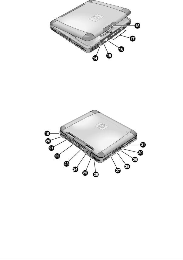
Figure 1-2. Front View
14. Headphone jack. |
17. Multimedia buttons (selected models). |
15. Status panel mode select button (selected models). |
18. Latch. |
16. Status panel (selected models). |
|
Figure 1-3. Rear/Left View
19.AC adapter jack.
20.PS/2 port (external mouse or keyboard).
21.Serial port.
22.Parallel port.
23.VGA port (external monitor).
24.TV output port.
25.Two USB ports.
26.Microphone jack.
27.Kensington lock slot (security connector).
28.PC card slots (upper and lower).
29.System-off switch (for resetting notebook).
30.PC card eject buttons.
31.Floppy disk drive.
1-4 |
Product Information |
HP Omnibook XE3 (Technology Codes GE and GD) |
|
Figure 1-4. Bottom View |
32. Battery. |
34. SDRAM cover. |
33. Battery latch. |
35. Mini-PCI cover. |
HP Omnibook XE3 (Technology Codes GE and GD) |
Product Information |
1-5 |

Operation
This section gives an overview of the notebook’s operation.
Turning the Notebook On and Off
You can start and stop the notebook using its power switch or blue standby button. However, at times you may want to use certain methods to start or stop the notebook—depending on power considerations, types of active connections, and start-up time.
Table 1-2. Activating Power Modes
Power mode |
To enter this mode |
To turn on again |
Display-off mode |
Allow timeout. |
Press any key or |
Power status LED stays green. |
|
move a pointing |
Saves minimal power. |
|
device to restore |
Turns off the display and hard disk. |
|
the display (“Instant |
Restarts quickly. |
|
On”). |
Maintains network connections. |
|
|
Standby mode |
Press the blue standby button. |
Press the blue |
Power status LED turns amber. |
–or– |
standby button to |
Saves significant power. |
Click Start, Turn Off Computer, |
return to your |
Turns off the display, hard drive, and other |
Stand By. |
current session |
components. |
–or– |
(“Instant-On”). |
Maintains the current session in SDRAM. |
Click Start, Shutdown, Standby. |
|
Restarts quickly. |
–or– |
|
Restores network connections. |
Allow timeout (Windows 98 only). |
|
Hibernate mode |
Click Start, Turn Off Computer, |
Press the blue |
Power status LED turns off. |
then press and hold Shift and click |
standby button to |
Saves maximum power. |
Hibernate. |
recover your |
Saves the current session to disk, then turns off. |
–or– |
previous session. |
Restores network connections. |
Click Start, Shut Down, Hibernate. |
|
|
–or– |
|
|
Allow timeout (Windows 98 only). |
|
Turn off |
Click Start, Turn Off Computer, |
Press the blue |
Power status LED turns off. |
Turn Off. |
standby button to |
Saves maximum power. |
–or– |
restart with a new |
Turns off without saving the current session. |
Click Start, Shut Down, Shut down |
session. |
At startup, resets everything, starts a new session, |
(recommended). |
|
and restores network connections with mini-PCI |
–or– |
|
and some PCMCIA cards. |
Slide the power switch and hold for |
|
|
five seconds (only if the Start menu |
|
|
procedure doesn’t work). |
|
1-6 |
Product Information |
HP Omnibook XE3 (Technology Codes GE and GD) |

Checking the Notebook’s Status
The notebook’s status lights—located above the keyboard—report power and battery status, keyboard status, and drive activity.
Figure 1-5. Status Lights
1. |
Power status. |
5. |
Scroll lock. |
2. |
Battery status. |
6. |
Floppy disk drive activity. |
3. |
Caps lock. |
7. |
Hard disk drive activity. |
4. |
Num lock. |
8. |
CD/DVD drive activity. |
HP Omnibook XE3 (Technology Codes GE and GD) |
Product Information |
1-7 |

Table 1-3. Status Lights
Indicator |
Meaning |
|
LED next to |
Power status |
|
power switch |
Green: the notebook is on. |
|
|
||
|
Amber: the notebook is in standby mode. |
|
|
No light: the notebook is off or in hibernate mode. |
|
|
Battery status |
|
|
Green: the AC adapter is connected and the battery is fully charged. |
|
|
Amber: the AC adapter is connected and the battery is charging. |
|
|
Red. the AC adapter is connected and the battery has a fault. |
|
|
Off: the AC adapter is not connected, or the adapter is connected but the battery is |
|
|
missing. |
|
A |
Caps Lock |
|
Caps Lock is active. |
||
|
||
1 |
Num Lock |
|
Num Lock is active. (The Keypad Lock must also be on to use the embedded keypad.) |
||
|
||
|
Scroll Lock |
|
|
Scroll Lock is active. |
|
|
Floppy disk drive activity |
|
|
Green: the notebook is accessing the floppy disk drive. |
|
|
Hard disk drive activity |
|
|
Green: the notebook is accessing the hard disk drive. |
|
|
CD/DVD drive activity |
|
|
Green: the notebook is accessing the CD/DVD drive. |
In addition, the status panel on the front of the notebook (if present) provides CD playback status and other system information. For details, see the section “Status panel” in the notebook’s Reference Guide.
1-8 |
Product Information |
HP Omnibook XE3 (Technology Codes GE and GD) |

Using Fn Hot Keys
The combination of the Fn key plus another key creates a hot key—a shortcut key sequence—for various system controls. To use a hot key, press and hold Fn, press the appropriate second key, then release both keys.
|
Table 1-4. Fn Hot Keys |
Hot Key |
Effect |
Fn+F1 |
Decreases the display brightness (TFT screens only). |
Fn+F2 |
Increases the display brightness (TFT screens only). |
Fn+F3 |
Decreases the display brightness (HPA screens only). |
Fn+F4 |
Increases the display brightness (HPA screens only). |
Fn+F5 |
Toggles among the built-in display, an external display, and simultaneous display on both. |
Fn+F7 |
Mutes the notebook’s speakers. |
Fn+F8 |
Toggles the built-in numeric keypad on and off. Does not affect an external keyboard. If |
|
Num Lock is on, the numeric functions are active; otherwise, cursor control is active. |
Fn+Lock key* |
Toggles Scroll Lock on and off. |
Fn+Up arrow |
Increases sound volume. |
Fn+Down arrow |
Decreases sound volume. |
*The Lock key is in the top row of the keyboard:
HP Omnibook XE3 (Technology Codes GE and GD) |
Product Information |
1-9 |
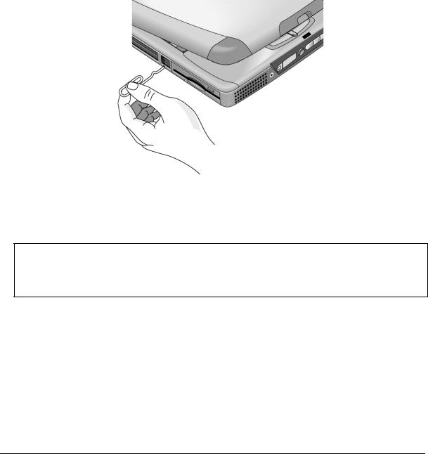
Resetting the Notebook
Occasionally, Windows or the notebook may stop responding, so that you cannot turn the notebook off. If this happens, try the following in the order listed:
•If possible, turn off the notebook from Windows: click Start, Turn Off Computer, Turn Off.
•Press Ctrl+Alt+Del, then click Shut Down.
•Slide and hold the power switch for about five seconds, until the notebook turns off.
•Insert a straightened paper clip into the system-off switch on the left side of the notebook (beneath the PC card eject buttons).
Figure 1-6. Resetting the Notebook
Once the notebook is off, press the blue standby button to restart.
Note
To boot from a CD or DVD, insert a bootable CD (such as a Recovery CD) into the drive, then restart. Press Esc when the HP logo appears, then select the CD-ROM/DVD drive as the temporary boot device.
1-10 Product Information |
HP Omnibook XE3 (Technology Codes GE and GD) |

Using the CD/DVD Player (selected models)
The multimedia buttons on the front of the notebook control the CD/DVD player, and work in much the same way as do the controls of a standalone CD or DVD player. The player operates whether the notebook is on, off, or in standby or hibernate mode. (When the notebook is on, the volume control buttons also govern the volume for most other audio applications.)
If the notebook is off or in standby or hibernate mode, slide the multimedia power switch to the left to activate the player. For details about using the CD/DVD player, see the notebook’s Reference Guide.
Figure 1-7. Multimedia Buttons
1.Multimedia power (use only when notebook is turned off or in standby or hibernate mode).
2.Previous track button.
3.Play/pause button.
4.Stop button (when notebook is on). Stop/eject (when notebook is off).
5.Next track button.
6.Volume control down button.
7.Volume control up button.
HP Omnibook XE3 (Technology Codes GE and GD) |
Product Information 1-11 |

Specifications
The following tables list the specifications for the notebook and its accessories. These are subject to change: for the latest versions, see the HP Notebook web site, www.hp.com/notebooks
(in Europe: www.europe.hp.com/notebooks).
Hardware Specifications
|
Table 1-5. XE3 Series Hardware Specifications |
Physical Attributes |
Size: |
|
13.03 x 10.72 x 1.59 in (331 x 272.3 x 40.5 mm) for 13.3/14.1-in models. |
|
13.46 x 10.92 x 1.65 in (342 x 276.6 x 42.0 mm) for 15.0-in models. |
|
Weight: 7 lbs minimum. |
|
|
Processor |
Technology code GD: AMD Duron and Athlon, 200-MHz FSB. |
|
Technology code GE: AMD K7 Duron and Athlon, 200-MHz FSB. |
|
|
Chip Set |
Ali M1647 + M1535. |
|
|
SDRAM |
133-MHz (PC133) SDRAM. |
|
No SDRAM on board. |
|
Two 1.25-in slots for expansion up to 512 MB, using two 256-MB SODIMM modules |
|
(144 pin, 3.3 V). |
Mass Storage |
Hard disk drive: |
|
– 10, 20, or 30 GB, PCI Bus Master Enhanced IDE. |
|
– 9.5 mm, 2.5 in. |
|
– Technology code GD: Supports Ultra DMA33/66. |
|
– Technology code GE: Supports Ultra DMA33/66/100. |
|
Floppy disk drive: 1.44 MB, 12.7 mm, 3-mode module. |
|
Optical drive: 24x CD, 8x DVD, 24x8x CD-RW (or higher), 8x4x24x8 DVD-CDRW |
|
(Combo), 12.7 mm module. |
Display |
13.3/14.1/15.0-in XGA (1024x768) or 15.0-in SXGA+ (1400x1050) TFT LCD. |
|
|
Graphics Controller |
Trident CBXP + 8 MB video RAM. |
Power |
Rechargeable lithium-ion battery (11.1 V) or NiMH battery (10.8 V). |
|
Battery life: up to 3 hrs depending on settings, usage, battery, and other factors. |
|
Charging time: 2.2 hrs (system off), 3 hrs (system on). |
|
Low-battery warning. |
|
Suspend/resume capability. |
|
AC adapter (DC-in) jack. |
|
Universal AC adapter: 100–240 Vac (50/60 Hz) input, 19 Vdc output, 60–65 W. |
Keyboard and |
87/88/90-key spill-proof QWERTY keyboard with 101/102 key emulation. |
Pointing Devices |
Embedded numeric keypad, 12 function (Fn) keys. |
|
Touch pad with on/off button. |
|
Left and right click buttons, center scroll button. |
|
NS87570 keyboard controller. |
Audio System |
CD player with built-in control buttons and status display (selected models). |
|
Two stereo speakers. |
|
Built-in microphone. |
|
Microphone and headphone jacks. |
Audio |
ESS Allegro (1988). |
|
– Integrated AC’97 CODEC. |
|
– HSP modem interface via MC’97 link. |
|
– Supports wake up on Ring. |
|
Modem CODEC ESS 2828 on mini-PCI slot. |
1-12 Product Information |
HP Omnibook XE3 (Technology Codes GE and GD) |

Communications |
LAN: |
|
– Transmission rate: 10 or 100 Mbps based on Auto-Negotiation. |
|
– Data standard: supports Category 3 (10Base-T/100Base-T) and Category 5 |
|
(100Base-TX) media coupler. |
|
– Power management: supports remote power-up using Wake on LAN from S3 |
|
(suspend) (WOL) technology and Deep power-down mode support. |
|
Modem: |
|
– Data modem standard: supports V.90, V.34, V.32bis, V.32, V.22bis, V.22, V.23, |
|
and V.21; Bell 212A and 103. |
|
– Error correction: V.42 LAPM, and MNP 2-4 error correction. |
|
– Data compression: V.42bis and MNP 5 data compression. |
|
– Fax modem standard: send/receive rates up to 14400 bps, V.17, V.29, V.27ter, |
|
and V.21 channel 2. |
|
– Power management: supports ACPI Power Management and wake up on Ring |
|
from S3. |
Input/Output |
Serial port: 9 pins (RS232), 16550 compatible. |
|
High-speed bidirectional parallel port: 25 pins, EPP/ECP capability. |
|
VGA port: 15 pins. |
|
PS/2: 6 pins, for keyboard, keypad or PS/2 mouse (Y adapter compatible). |
|
Microphone-in, headphone-out jacks. |
|
Internal microphone. |
|
Two USB ports. |
|
Composite TV-out. |
|
RJ-45 (LAN), RJ-11 (modem) jacks |
Expandability |
Two Type II or one Type III 16-/32-bit PCMCIA slots. |
Options |
64/128/256-MB PC133 SODIMM: 3.3 V, 144-pin, SDRAM. |
|
Mini-PCI modem, supporting wake-up on Ring# from D3 (cold) with AC-in. |
|
Mini-PCI modem/LAN combo, supporting wake-up on Ring# & PME# from D3 (cold) |
|
with AC-in. |
Environmental Limits Operating temperature: 0 to 40 ° C (32 to 104 ° F). Storage temperature: –20 to 65 ° C (–4 to 149 ° F).
Operating humidity: 20% (10% on some models) to 90% RH (5 to 35 °C). Operating altitude: up to 3050 m (10,000 ft).
Storage altitude: up to 12,200 m (40,000 ft).
HP Omnibook XE3 (Technology Codes GE and GD) |
Product Information 1-13 |

|
|
Table 1-6. XE3 Series Accessories |
Accessory |
|
Description |
Memory |
|
|
|
|
|
F1457C |
|
64-MB SDRAM PC133 SODIMM expansion module |
F3495A |
|
128-MB SDRAM PC133 SODIMM expansion module |
F3496A |
|
256-MB SDRAM PC133 SODIMM expansion module |
Power Options |
|
|
|
|
|
F1455A |
|
Auto/airline AC adapter (75-watt) |
F1781A |
|
Ultra Slimline AC adapter (60-watt) |
F2024A/B |
|
Li-Ion battery (9 cell) |
F2297A |
|
Car adapter (Europe only) |
8120-6312 |
|
Replacement power cord, 250 Vac, 2.5 A (Australia/New Zealand) |
8120-6313 |
|
Replacement power cord, 125 Vac, 3 A (U.S./Canada/Taiwan/Mexico/Philippines) |
8120-6314 |
|
Replacement power cord, 250 Vac, 2.5 A (Europe/Egypt/Israel/Saudi Arabia) |
8120-6316 |
|
Replacement power cord, 125 Vac, 3 A (Japan) |
8120-6317 |
|
Replacement power cord, 250 Vac, 2.5 A (South Africa) |
8120-8367 |
|
Replacement power cord, 250 Vac, 2.5 A (Argentina) |
8120-8373 |
|
Replacement power cord, 250 Vac, 2.5 A (People’s Republic of China) |
8120-8452 |
|
Replacement power cord, 250 Vac, 2.5 A (Chile) |
8120-8699 |
|
Replacement power cord, 250 Vac, 2.5 A (UK [EPSR] Hong Kong/Singapore) |
8121-0702 |
|
Replacement power cord, 250 Vac, 2.5 A (India) |
Adapters |
|
|
|
|
|
F1469A |
|
PS/2 “Y” adapter |
PC Cards |
|
|
|
|
|
F1625A |
|
56-Kbps global modem v.90 PC card (for support only) |
F1626A |
|
10/100 LAN CardBus Ethernet PC card |
F1627A |
|
56-Kbps US-only modem PC card (for support only) |
P1980A |
|
USB Wireless LAN 802.11b PC card |
P1981A |
|
USB Wireless LAN access point PC card |
F1985A |
|
USB-NIC Ethernet adapter |
F2135B/C |
|
Wireless Comm access point PC card |
F2136B |
|
Wireless Comm PC card (128-bit) |
F2196A |
|
3Com Bluetooth PC card |
Security Accessories |
|
|
F1645A |
|
Kensington MicroSaver Notebook Security System |
F1747A |
|
Port Defcon 1 Notebook Security System |
Other |
|
|
P1534A |
|
HP amplified external speakers |
P1977A |
|
USB Compact Flash & IBM Microdrive reader |
P1978A |
|
USB web camera |
F2100A |
|
USB optical mouse |
1-14 Product Information |
HP Omnibook XE3 (Technology Codes GE and GD) |
Internal Design
The motherboard PCA is the central component of the notebook’s design, and plays a role in virtually all system functions. The CPU module and most other subsystems connect to the motherboard.
The following figure shows the connections among the notebook’s replaceable electronic modules. In addition, the table on page 1-16 lists the roles that the replaceable modules play in each of the notebook’s functional subsystems.
Display assembly
CPU module |
Video PCA |
Switchboard PCA |
Top case
(speakers, touch pad, click buttons)
Mini-PCI
PCA
Motherboard PCA
Heatsink/fan
assembly
CD/DVD drive
PCMCIA |
PCMCIA |
cards |
sockets (2) |
SDRAM
module
Floppy disk drive
Headphone |
CD player |
Keyboard |
Battery |
PCA |
PCA |
|
|
|
|
Hard disk drive
Figure 1-8. Replaceable Module Diagram
HP Omnibook XE3 (Technology Codes GE and GD) |
Product Information 1-15 |

|
|
Table 1-7. Functional Structure |
|
Function |
Components Used |
|
Component Roles |
|
|
|
|
Bootup |
CPU module |
|
Main processor. |
|
Motherboard |
|
Primary system circuitry. |
|
Floppy disk module |
|
First source of disk-based startup code. |
|
Hard disk drive |
|
Second source of disk-based startup code. |
Processor |
CPU module |
|
Main processor, numeric data processor, L1 and L2 cache. |
|
Motherboard |
|
Primary system circuitry. |
Memory |
Motherboard |
|
No onboard RAM. |
|
SDRAM module |
|
Changeable RAM (2 slots). |
|
Video PCA |
|
Video RAM. |
Power |
Battery |
|
Power storage. |
|
Motherboard |
|
Power control circuitry, AC adapter socket, lid switch, system-off switch, |
|
|
|
power supply. |
|
Switchboard PCA |
|
Power switch, standby button. |
|
AC adapter |
|
AC-to-DC converter. |
Display |
Motherboard |
|
Video controller. |
|
Display assembly |
|
Display output, backlight, power converter for backlight. |
|
Video PCA |
|
Display drivers, LVDS processing, display/graphics controller, video |
|
|
|
RAM. |
Hard disk |
Motherboard |
|
Hard disk controller. |
|
Hard disk drive |
|
Hard disk mechanism. |
Floppy drive |
Motherboard |
|
I/O controller, floppy connector. |
|
Floppy disk module |
|
Floppy disk mechanism. |
Keyboard |
Motherboard |
|
Keyboard controller, keyboard BIOS. |
|
Keyboard |
|
Key switches. |
Touch pad |
Motherboard |
|
Keyboard BIOS. |
|
Top case |
|
Touch pad sensor, click buttons, controller (PS/2 output). |
Audio |
Motherboard |
|
Audio controller, audio decoder, speaker amplifier, external microphone |
|
|
|
jack. |
|
Switchboard PCA |
|
Microphone. |
|
Headphone PCA |
|
Earphone amplifier. |
|
Top case |
|
Speakers. |
Status |
Motherboard |
|
LED circuitry, keyboard controller. |
|
Switchboard PCA |
|
Status LEDs. |
|
CD player PCA |
|
CD/DVD status display. |
Serial |
Motherboard |
|
I/O controller, serial connector. |
|
|
|
|
Parallel |
Motherboard |
|
I/O controller, parallel connector. |
|
|
|
|
PS/2 port |
Motherboard |
|
Keyboard controller, PS/2 connector. |
|
|
|
|
USB |
Motherboard |
|
Bus controller, USB connectors. |
|
|
|
|
PCMCIA |
Motherboard |
|
PCMCIA controller. |
|
PCMCIA sockets |
|
PCMCIA connectors. |
1-16 Product Information |
HP Omnibook XE3 (Technology Codes GE and GD) |
2
Removal and Replacement
This chapter shows how to remove and replace the notebook’s components and assemblies. The items marked by • in the following table are user-replaceable.
Table 2-1. Removal Cross-Reference
• Battery (page 2-4). |
Heatsink assembly (with fan) (page 2-29). |
Carrier, hard disk drive (page 2-15). |
Keyboard (page 2-12). |
Case, bottom (page 2-35). |
Module, CPU (page 2-30). |
Case, top (page 2-22). |
• Module, SDRAM (page 2-5). |
Cover, keyboard (page 2-10). |
PCA, CD player (page 2-24). |
• Cover, mini-PCI (page 2-9). |
PCA, headphone (page 2-41). |
• Cover, SDRAM (page 2-9). |
• PCA, mini-PCI (page 2-7). |
• Covers, screw (page 2-9). |
PCA, motherboard (page 2-35). |
Display assembly (page 2-18). |
PCA, switchboard (page 2-41). |
Doors, PCMCIA (page 2-38). |
PCA, video (page 2-27). |
Drive, CD/DVD (page 2-34). |
Saddle, hinge set (page 2-25). |
Drive, floppy disk (page 2-32). |
Socket, PCMCIA (page 2-41). |
Drive, hard disk (page 2-14). |
|
|
|
Caution
Always provide proper grounding when performing repairs. Without proper grounding, an electrostatic discharge can damage the notebook and its components.
Notes
To reassemble a component, perform the removal procedure in reverse order. Any special notes required for reassembly are included at the end of each section.
 Symbols like this throughout this chapter show approximate full-size screw outlines. You can use these to verify the sizes of screws before you install them. Installing a wrong-size screw can damage the notebook. (The symbol at the left represents an M2.5×5 mm T-head screw.)
HP Omnibook XE3 (Technology Codes GE and GD) |
Removal and Replacement |
2-1 |

Disassembly Flowchart
The following diagram shows the general “path” you will use in disassembling the notebook to access any particular component.
Only if not removing motherboard
or bottom case
If removing only heatsink assembly or CPU module
Start
Battery, AC adapter, SDRAM modules, mini-PCI PCA
Keyboard cover
Keyboard
Hard disk drive assembly
Display assembly
Top case assembly
Hinge saddle set
•CD/DVD drive assembly
•Video PCA
•Floppy disk drive assembly
•Headphone PCA
Heatsink assembly (with fan)
CPU module
Motherboard or bottom case
 Switchboard PCA
(also remove if removing motherboard or bottom case assembly)
 CD player PCA
 PCMCIA doors
Figure 2-1. Disassembly Flow
2-2 |
Removal and Replacement |
HP Omnibook XE3 (Technology Codes GE and GD) |

Table 2-2. Required Equipment
•#0 Phillips screwdriver, preferably magnetized.
•Small flat-blade screwdriver.
•5 mm hexagonal socket screwdriver.
•Electrostatic device (wristband and pad).
Table 2-3. Recommended Screw Torques
Screw Thread Size |
Torque (cm-kgf) |
Torque (in-lbf) |
M2.5 (2–11 mm long) |
3.0 – 3.5 |
2.6 – 3.0 |
M2.5 (12–19 mm long) |
2.5 – 3.0 |
2.2 – 2.6 |
M3 |
3.0 – 3.5 |
2.6 – 3.0 |
NOTES
HP Omnibook XE3 (Technology Codes GE and GD) |
Removal and Replacement |
2-3 |

Removing the Battery
(User-Replaceable)
Required Equipment
• None.
Removal Procedure
• Slide the battery’s release latch, then lift the battery out of its compartment.
Figure 2-2. Removing the Battery
Reassembly Notes
•Insert the front (rounded) end of the battery into the battery compartment, and lower the back end in until it clicks into place.
2-4 |
Removal and Replacement |
HP Omnibook XE3 (Technology Codes GE and GD) |
Removing an SDRAM Module
(User-Replaceable)
The notebook has no SDRAM on its motherboard, but has slots for two SDRAM modules.
Table 2-4. SDRAM Module Replacement Part Numbers
Description |
Part Number |
Exchange Part Number |
Module, SDRAM, 128 MB, PC133 SODIMM |
1818-8504 |
|
Module, SDRAM, 256 MB, PC133 SODIMM |
1818-8635 |
|
Caution
Provide proper grounding and handle the SDRAM module only by its edges, or you could damage the module through electrostatic discharge.
Required Equipment
• #0 Phillips screwdriver.
Removal Procedure
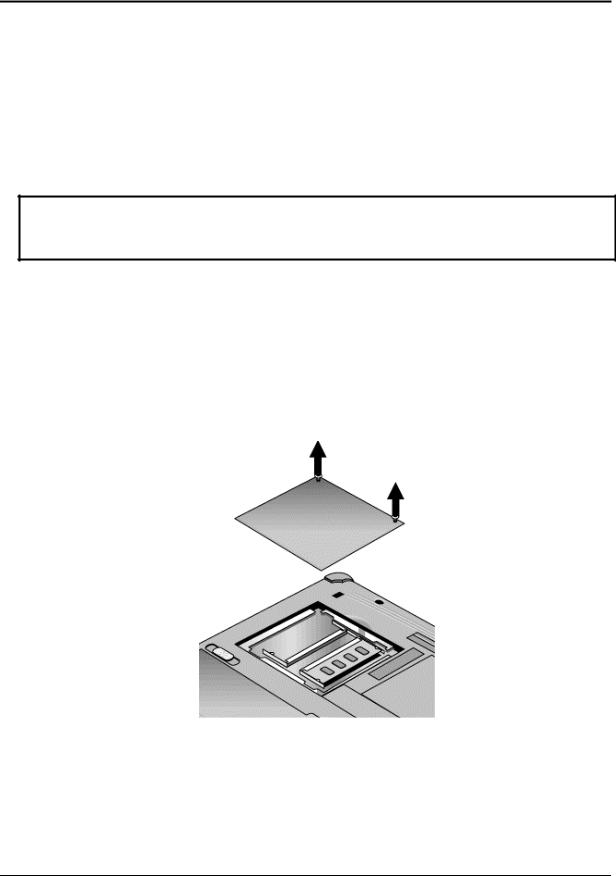
1.Unplug the AC adapter, if present, and remove the battery.
2.On the bottom of the notebook, loosen both screws holding the SDRAM cover (the cover retains the screws), and remove the cover.
Figure 2-3. Removing the SDRAM Cover
HP Omnibook XE3 (Technology Codes GE and GD) |
Removal and Replacement |
2-5 |
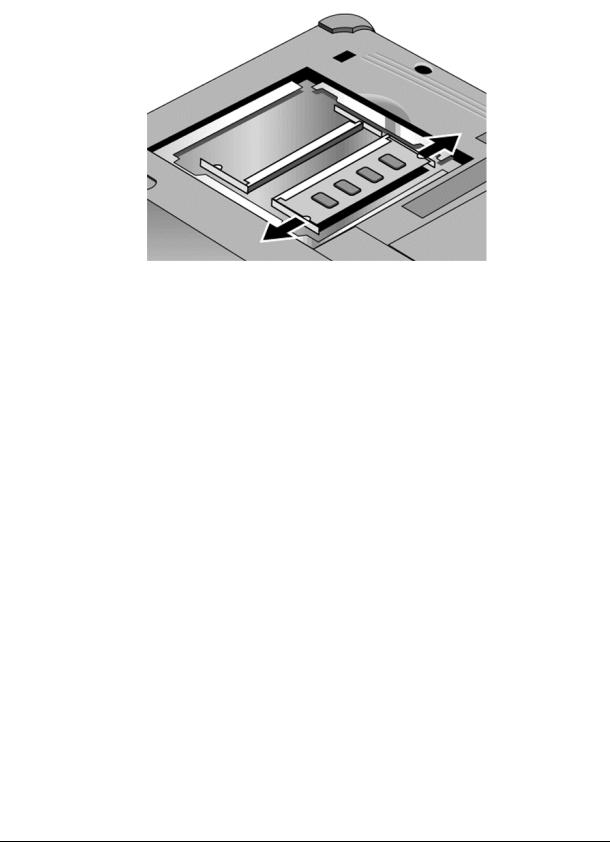
3.Press outward to release the latches at the sides of the SDRAM module, so the free edge of the module pops up.
Figure 2-4. Removing an SDRAM Module
4. Pull the module out of the connector.
Reassembly Notes
•Gently press the SDRAM module into the connector at an angle of about 30°, until it is fully inserted. Then press down on both sides of the module until the latches snap closed.
2-6 |
Removal and Replacement |
HP Omnibook XE3 (Technology Codes GE and GD) |

Removing the Mini-PCI PCA (selected models)
(User-Replaceable)
Certain notebook models include a mini-PCI PCA that contains either a modem or modem/LAN.
Table 2-5. Mini-PCI PCA Replacement Part Numbers
Description |
Part Number |
Exchange Part Number |
PCA, mini-PCI (LAN/modem) |
F2409-60907 |
|
PCA, mini-PCI (LAN/modem) Malaysia |
F2409-60908 |
|
PCA, mini-PCI (modem) |
F2409-60909 |
|
PCA, mini-PCI (modem) Malaysia |
F2409-60910 |
|
Caution
Provide proper grounding and handle the PCA only by its edges, or you could damage it through electrostatic discharge.
Required Equipment
• #0 Phillips screwdriver.
Removal Procedure
1.Unplug the AC adapter, if present, and remove the battery.
2.Loosen the screw holding the mini-PCI cover (the cover retains the screw), and remove the cover.
3.Press outward to release the latches at the sides of the PCA, and carefully lift its free edge up. Note that the PCA has several sticky pads on the side facing the motherboard.
4.Disconnect the cable (modem models only) or cables (modem/LAN models only) from the PCA.
5.Gently pull the PCA out of its connector.
HP Omnibook XE3 (Technology Codes GE and GD) |
Removal and Replacement |
2-7 |

Figure 2-5. Removing the Mini-PCI PCA
Reassembly Notes
•Reattach the cable (modem models only) or cables (modem/LAN models only) to the PCA, and tuck them into the compartment.
•Gently press the PCA into the connector at an angle of about 30°, until it is fully inserted. Then press down on both sides of the PCA until the latches snap closed.
•Make sure sticky pads on the underside of the PCA are intact. Replace if needed.
2-8 |
Removal and Replacement |
HP Omnibook XE3 (Technology Codes GE and GD) |
 Loading...