


®
HP Omnibook XE4100
HP Omnibook XE4500
Technology Codes KB, KC
Service Manual

Notice
In a continuing effort to improve the quality of our products, technical and environmental information in this document is subject to change without notice.
This manual and any examples contained herein are provided “as is” and are subject to change without notice. Hewlett-Packard Company makes no warranty of any kind with regard to this manual, including, but not limited to, the implied warranties of merchantability and fitness for a particular purpose. Hewlett-Packard Co. shall not be liable for any errors or for incidental or consequential damages in connection with the furnishing, performance, or use of this manual or the examples herein.
Consumer transactions in Australia and the United Kingdom: The above disclaimers and limitations shall not apply to Consumer transactions in Australia and the United Kingdom and shall not affect the statutory rights of Consumers.
© Copyright Hewlett-Packard Company 1998–2002. All rights reserved. Reproduction, adaptation, or translation of this manual is prohibited without prior written permission of Hewlett-Packard Company, except as allowed under the copyright laws.
The programs that control this product are copyrighted and all rights are reserved. Reproduction, adaptation, or translation of those programs without prior written permission of Hewlett-Packard Co. is also prohibited.
Portions of the programs that control this product may also be copyrighted by Microsoft Corporation, SystemSoft Corp., Phoenix Technologies, Ltd., ATI Technologies Inc., and Adobe Systems Incorporated. See the individual programs for additional copyright notices.
This product incorporates copyright protection technology that is protected by method claims of certain U.S. patents and other intellectual property rights owned by Macrovision Corporation and other rights owners. Use of this copyright protection technology must be authorized by Macrovision Corporation and is intended for home and other limited viewing uses only unless otherwise authorized by Macrovision Corporation. Reverse engineering or disassembly is prohibited.
Microsoft®, MS-DOS®, and Windows® are U.S. registered trademarks of Microsoft Corporation. Pentium® and the Intel Inside logo are U.S. registered trademarks and Celeron™ and SpeedStep™ are U.S. trademarks of Intel Corporation. Adobe® and Acrobat® are trademarks of Adobe Systems Incorporated.
All certifications may not be completed at product introduction. Check with your HP reseller for certification status.
This equipment is subject to FCC rules. It will comply with the appropriate FCC rules before final delivery to the buyer.
Hewlett-Packard Company
Mobile Computing Division
19310 Pruneridge Ave.
Cupertino, CA 95014, U.S.A.
Edition History
Edition 1 (KB, KC) .......................... |
May 2002 |
ii |
HP Omnibook XE4100/XE4500 |

Contents
1. Product Information.................................................................................................. |
1-1 |
Features ......................................................................................................................................... |
1-3 |
Operation....................................................................................................................................... |
1-6 |
Turning the Notebook On and Off ......................................................................................... |
1-6 |
Checking the Status of the Notebook ..................................................................................... |
1-7 |
Using Fn Hot Keys ................................................................................................................. |
1-8 |
Resetting the Notebook .......................................................................................................... |
1-9 |
Specifications .............................................................................................................................. |
1-10 |
Internal Design ............................................................................................................................ |
1-14 |
2. Removal and Replacement........................................................................................ |
2-1 |
Disassembly Flowchart.................................................................................................................. |
2-3 |
Removing the Battery (User-Replaceable).................................................................................... |
2-4 |
Removing a SDRAM Module (User-Replaceable)....................................................................... |
2-5 |
Removing the Wireless LAN Mini-PCI Card (User-Replaceable) ............................................... |
2-6 |
Removing the Hard Disk Drive (User-Replaceable)..................................................................... |
2-7 |
Replacing Small Parts (User-Replaceable) ................................................................................... |
2-9 |
Removing the Keyboard Cover (User-Replaceable) ................................................................... |
2-10 |
Removing the Speaker Assembly (User-Replaceable)................................................................ |
2-12 |
Removing the Keyboard (User-Replaceable).............................................................................. |
2-13 |
Removing the Switchboard PCA (User-Replaceable) ................................................................ |
2-15 |
Removing the CD/DVD Drive (User-Replaceable).................................................................... |
2-16 |
Removing the Display Assembly (HP Authorized Service Providers Only) .............................. |
2-17 |
Removing the Top Case (HP Authorized Service Providers Only) ............................................ |
2-20 |
Removing the Floppy Drive (HP Authorized Service Providers Only) ...................................... |
2-22 |
Removing the Infrared (I/R) PCA (HP Authorized Service Providers Only) ............................. |
2-25 |
Removing the Heatsink (with Fan) (HP Authorized Service Providers Only)............................ |
2-27 |
Removing the CPU Module (HP Authorized Service Providers Only) ...................................... |
2-29 |
Removing the Motherboard (HP Authorized Service Providers Only)....................................... |
2-31 |
Replacing Components on a Bottom Case .................................................................................. |
2-35 |
Repairing the BIOS IC (HP Authorized Service Providers Only) .............................................. |
2-37 |
Removing Other Components (HP Authorized Service Providers Only) ................................... |
2-39 |
3. Troubleshooting and Diagnostics ............................................................................. |
3-1 |
Support by Authorized Service Providers ..................................................................................... |
3-1 |
Troubleshooting ............................................................................................................................ |
3-2 |
Checking for Customer Abuse ............................................................................................... |
3-3 |
Troubleshooting the Problem ................................................................................................. |
3-3 |
Verifying the Repair ............................................................................................................... |
3-4 |
Suggestions for Troubleshooting............................................................................................ |
3-5 |
Diagnostic Tools ......................................................................................................................... |
3-17 |
e-Diagtools Diagnostic Program .......................................................................................... |
3-17 |
Power-On Self-Test .............................................................................................................. |
3-20 |
Sycard PCCtest 450/460 PC Card (Optional) ...................................................................... |
3-25 |
Windows Management Instrumentation (WMI)................................................................... |
3-26 |
BIOS Setup Utility................................................................................................................ |
3-27 |
HP Omnibook XE4100/XE4500 |
iii |

4. |
Replaceable Parts....................................................................................................... |
4-1 |
5. |
Reference Information............................................................................................... |
5-1 |
|
Password Removal Policy............................................................................................................. |
5-1 |
|
Hewlett-Packard Display Quality Statement................................................................................. |
5-2 |
|
Service Notes and Obsolete Parts ................................................................................................. |
5-4 |
iv |
HP Omnibook XE4100/XE4500 |

Figures
Figure 1-1. Omnibook XE4100/XE4500— Front View...................................................................... |
1-3 |
Figure 1-2. Omnibook XE4100/XE4500— Back View ...................................................................... |
1-4 |
Figure 1-3. Omnibook XE4100/XE4500— Bottom View................................................................... |
1-5 |
Figure 1-4. Resetting the Notebook ..................................................................................................... |
1-9 |
Figure 1-5. Replaceable Module Diagram ......................................................................................... |
1-14 |
Figure 2-1. Disassembly Flow.............................................................................................................. |
2-3 |
Figure 2-2. Removing the Battery........................................................................................................ |
2-4 |
Figure 2-3. Removing an SDRAM Module ......................................................................................... |
2-5 |
Figure 2-4. Removing the Mini-PCI Card............................................................................................ |
2-6 |
Figure 2-5. Removing the Hard Disk Drive ......................................................................................... |
2-7 |
Figure 2-6. Removing the Hard Disk Drive Tray................................................................................. |
2-8 |
Figure 2-7. Removing the Keyboard Cover ....................................................................................... |
2-11 |
Figure 2-8. Removing the Speaker Assembly.................................................................................... |
2-12 |
Figure 2-9. Removing the Keyboard .................................................................................................. |
2-14 |
Figure 2-10. Removing the Switchboard PCA................................................................................... |
2-15 |
Figure 2-11. Removing the CD/DVD Drive ...................................................................................... |
2-16 |
Figure 2-12. Removing the Display Assembly .................................................................................. |
2-18 |
Figure 2-13. Removing the Top Case ................................................................................................ |
2-21 |
Figure 2-14. Removing the Floppy Drive .......................................................................................... |
2-23 |
Figure 2-15. Removing the I/R PCA.................................................................................................. |
2-26 |
Figure 2-16. Removing the Heatsink (with Fan)................................................................................ |
2-27 |
Figure 2-17. Removing the CPU Module .......................................................................................... |
2-29 |
Figure 2-18. Removing the Motherboard........................................................................................... |
2-32 |
Figure 2-19. Example of Serial Number Label .................................................................................. |
2-35 |
Figure 2-20. Replacing the Antennas................................................................................................. |
2-36 |
Figure 2-21. Removing a PCMCIA Door .......................................................................................... |
2-36 |
Figure 2-22. Boot-Block Jumper........................................................................................................ |
2-38 |
Figure 3-1. Basic Troubleshooting Steps ............................................................................................. |
3-2 |
Figure 4-1. Exploded View .................................................................................................................. |
4-2 |
HP Omnibook XE4100/XE4500 |
v |

Tables
Table 1-1. Omnibook XE4100/XE4500 Notebooks............................................................................ |
1-1 |
Table 1-2. Product Comparisons.......................................................................................................... |
1-2 |
Table 1-3. Activating Power Modes .................................................................................................... |
1-6 |
Table 1-4. Main Status Lights (front of notebook) .............................................................................. |
1-7 |
Table 1-5. Keyboard Status Lights....................................................................................................... |
1-7 |
Table 1-6. Fn Hot Keys........................................................................................................................ |
1-8 |
Table 1-7. Omnibook X4100 and XE4500 Specifications ................................................................ |
1-10 |
Table 1-8. Omnibook XE4100, XE4500 Accessories ....................................................................... |
1-13 |
Table 1-9. Functional Structure Description...................................................................................... |
1-15 |
Table 2-1. Removal Cross-Reference .................................................................................................. |
2-1 |
Table 2-2. Required Equipment........................................................................................................... |
2-2 |
Table 2-3. Recommended Screw Torque Values................................................................................. |
2-2 |
Table 2-4. Replacing Small Parts (User-Replaceable)......................................................................... |
2-9 |
Table 2-5. Removing Omnibook XE4100/XE4500 Components...................................................... |
2-39 |
Table 3-1. ASP Support Options ......................................................................................................... |
3-1 |
Table 3-2. Scope of Diagnostic Tools.................................................................................................. |
3-5 |
Table 3-3. Troubleshooting Suggestions ............................................................................................. |
3-6 |
Table 3-4. POST Terminal-Error Beep Codes................................................................................... |
3-20 |
Table 3-5. POST Messages................................................................................................................ |
3-23 |
Table 3-6. Sycard PCCtest Commands.............................................................................................. |
3-25 |
Table 3-7. BIOS Setup Menus and Parameters.................................................................................. |
3-27 |
Table 4-1. Omnibook Replaceable Parts.............................................................................................. |
4-3 |
Table 4-2. Accessory Replaceable Parts .............................................................................................. |
4-6 |
Table 4-3. Part Number Reference ...................................................................................................... |
4-6 |
Table 5-1. Omnibook XE4100/XE4500 LCD Guidelines................................................................... |
5-3 |
vi |
HP Omnibook XE4100/XE4500 |

Introduction
This manual provides reference information for servicing the HP Omnibook XE4100 (technology code KC) and XE4500 (technology code KB) notebook computers. It is for use by HP-authorized service personnel while installing, servicing, and repairing these products.
The manual is designed as a self-paced guide that will train you to install, configure, and repair these notebooks. The manual is self-contained, so you can follow it even without having equipment available.
The following table lists other sources of information about the notebook computers and related products.
Source |
Address or Number |
Comments |
HP Notebook Web Site |
http://www.hp.com/notebooks |
|
|
(http://www.europe.hp.com/notebook, |
|
|
European mirror) |
|
HP Business Support web |
www.hp.com/go/bizsupport |
|
Site |
|
|
HP Partnership Web |
http://partner.americas.hp.com |
Restricted to Authorized Resellers |
|
|
only. |
HP Asia Pacific Channel |
http://www.hp.com.au |
Restricted to DPSP Partners only. |
Support Centre for DPSP |
|
|
Partners |
|
|
HP/MCD web site |
http://www.mcd.hp.com |
HP’s internal web site for division |
|
|
information. |
America Online |
Keyword: HP |
Call (800) 827-6364 for membership |
|
|
within the US. |
CompuServe |
GO HP |
Call (800) 524-3388 for membership |
|
|
within the US. |
HP Support Assist CD-ROM |
(800) 457-1762 |
US and Canada. |
|
(801) 431-1587 |
Outside US and Canada. |
Microsoft Windows manual |
|
Information about Windows operating |
|
|
system. |
Microsoft Web |
http://www.microsoft.com |
Information and updates for Windows |
|
|
operating systems. |
HP Omnibook XE4100/XE4500 |
vii |

1
Product Information
HP Omnibook XE4100 and XE4500 notebook computers provide outstanding performance and expandability in a conveniently portable form. Their high-performance components use the latest technologies to enable them to serve as desktop computers or portable multimedia presentation tools. Note that the following list of products is current at the time of publication but is subject to change.
Table 1-1. Omnibook XE4100/XE4500 Notebooks
Omnibook |
|
|
Hard |
CD/DVD |
Standard |
|
|
|
Product * |
CPU ** |
Display |
Drive |
Drives |
SDRAM/ |
Communication |
Battery |
|
|
|
|
|
|
Video Mem |
|
|
|
Omnibook XE4100 |
|
|
|
|
|
|
|
|
|
|
|
|
|
|
|
|
|
F4641 J/H |
Celeron 1.13 GHz |
14.1-in XGA |
20 GB |
CD |
128 MB/uma |
Modem/LAN |
Ni-Mh |
|
F4642 J/H |
Celeron 1.13 GHz |
14.1-in XGA |
20 GB |
DVD |
128 |
MB/uma |
Modem/LAN |
Li-Ion |
F4643 J/H |
Celeron 1.2 GHz |
14.1-in XGA |
30 GB |
DVD |
256 |
MB/uma |
Modem/LAN |
Li-Ion |
F4644 J/H |
Celeron 1.2 GHz |
14.1-in XGA |
30 GB |
CDRW/DVD |
256 MB/uma |
Modem/LAN |
Li-Ion |
|
F4646 J/H |
Celeron 1.2 GHz |
14.1-in XGA |
20 GB |
CD |
128 MB/uma |
Modem/LAN |
Ni-Mh |
|
F4647 J/H |
Celeron 1.2 GHz |
14.1-in XGA |
20 GB |
CD |
128 |
MB/uma |
Modem/LAN |
Li-Ion |
F4648 J/H |
Celeron 1.2 GHz |
14.1-in XGA |
30 GB |
CDRW/DVD |
128 MB/uma |
Modem/LAN |
Ni-Mh |
|
F4649 H |
Celeron 1.2 Ghz |
14.1-in XGA |
20 GB |
CDRW/DVD |
128 MB/uma |
Modem/LAN |
Li-Ion |
|
F4650 J/H |
Celeron 1.2 GHz |
14.1-in XGA |
20 GB |
DVD |
256 |
MB/uma |
Modem/LAN |
Li-Ion |
Omnibook XE4500 |
|
|
|
|
|
|
|
|
F4867 J/H |
Pentium 4-M 1.6 GHz |
14.1-in XGA |
20 GB |
CD |
128 |
MB/16 MB |
Modem/LAN |
Li-Ion |
F4868 J/H |
Pentium 4-M 1.6 GHz |
14.1-in XGA |
30 GB |
DVD |
128 MB/16 MB |
Modem/LAN |
Li-Ion |
|
F4869 J/H |
Pentium 4-M 1.6 GHz |
14.1-in XGA |
20 GB |
DVD |
128 MB/32 MB |
Modem/LAN |
Li-Ion |
|
F4870 J/H |
Pentium 4-M 1.6 GHz |
14.1-in XGA |
30 GB |
DVD |
256 MB/32 MB |
Modem/LAN |
Li-Ion |
|
F4871 J/H |
Pentium 4-M 1.6 GHz |
14.1-in XGA |
30 GB |
CDRW/DVD |
256 MB/32 MB |
Modem/LAN |
Li-Ion |
|
F4872 J/H |
Pentium 4-M 1.6 GHz |
14.1-in XGA |
30 GB |
CDRW/DVD |
256 MB/32 MB |
Modem/LAN/802.11 |
Li-Ion |
|
F4873 J/H |
Pentium 4-M 1.6 GHz |
15-in XGA |
20 GB |
DVD |
128 MB/32 MB |
Modem/LAN |
Li-Ion |
|
F4874 J/H |
Pentium 4-M 1.6 GHz |
15-in XGA |
30 GB |
DVD |
256 MB/32 MB |
Modem/LAN |
Li-Ion |
|
F4875 J/H |
Pentium 4-M 1.6 GHz |
15-in XGA |
30 GB |
CDRW/DVD |
256 MB/32 MB |
Modem/LAN |
Li-Ion |
|
F4876 J/H |
Pentium 4-M 1.7 GHz |
15-in SXGA+ |
40 GB |
CDRW/DVD |
256 MB/32 MB |
Modem/LAN/802.11 |
Li-Ion |
|
F4877 H |
Pentium 4-M 1.6 GHz |
14.1-in XGA |
20 GB |
CDRW/DVD |
128 MB/32 MB |
Modem/LAN |
Li-Ion |
|
F4878 H |
Pentium 4-M 1.7 GHz |
15-in XGA |
30 GB |
CDRW/DVD |
256 MB/32 MB |
Modem/LAN |
Li-Ion |
|
F4880 J/H |
Pentium 4-M 1.6 GHz |
14.1-in XGA |
30 GB |
DVD |
256 |
MB/32 MB |
Modem/LAN/802.11 |
Li-Ion |
F4881 J/H |
Pentium 4-M 1.7 GHz |
15-in XGA |
30 GB |
CDRW/DVD |
256 MB/32 MB |
Modem/LAN/802.11 |
Li-Ion |
|
F4883 J/H |
Pentium 4-M 1.6 GHz |
14.1-in XGA |
20 GB |
CD |
128 |
MB/16 MB |
Modem/LAN |
Li-Ion |
F4884 J/H |
Pentium 4-M 1.6 GHz |
14.1-in XGA |
30 GB |
CDRW/DVD |
128 MB/32 MB |
Modem/LAN |
Li-Ion |
|
F4885 J/H |
Pentium 4-M 1.6 GHz |
15-in SXGA+ |
30 GB |
CD |
256 MB/32 MB |
Modem/LAN |
Li-Ion |
|
F4886 J/H |
Pentium 4-M 1.7 GHz |
15-in XGA |
40 GB |
CDRW/DVD |
256 MB/32 MB |
Modem/LAN/802.11 |
Li-Ion |
|
This table lists only base product configurations—custom configurations are not included.
* The J/H suffix indicates the notebook’s OS: J = Windows XP Professional with Windows 2000 Recovery CDs, H = Windows XP Home.
** Intel Mobile Pentium 4-M and Intel Mobile Celeron processors.
HP Omnibook XE4100/XE4500 |
Product Information |
1-1 |

Table 1-2. Product Comparisons
|
Omnibook XE4500 |
Omnibook XE4100 |
Processor* |
Pentium 4-M (1.6 to 1.7 GHz). |
Celeron (1.13 to 1.20 GHz). |
Memory |
Up to 2 GB (2048 MB) SDRAM using |
Up to 1 GB (1024 MB) SDRAM using 512 MB |
|
1 GB MB modules (when available); |
modules. |
|
otherwise, up to 1 GB (1024 MB) SDRAM |
At least 128 MB SDRAM preinstalled. |
|
using 512 MB modules. |
|
|
At least 128 MB SDRAM preinstalled. |
|
Display |
15.0-inch XGA (1024 x 768) or SXGA+ |
15.0-inch XGA (1024 x 768) or 14.1-inch XGA |
|
(1400 x 1050) or 14.1-inch XGA (1024 x |
(1024 x 768) active-matrix TFT. |
|
768) active-matrix TFT. |
|
Video |
ATI Mobility Radeon graphics accelerator |
VIA graphics with up to 32 MB dynamically |
|
with 16 or 32 MB DDR graphics memory, 4x |
allocated video RAM [16 MB (default) video RAM |
|
AGP graphics capability. |
shared with system RAM]. |
Operating |
Windows XP Professional or Home |
Windows XP Professional or Home preinstalled. |
System |
preinstalled. |
|
|
|
|
Power States |
On, Standby, Hibernate, Off. |
On, Standby, Hibernate, Off. |
|
|
|
* Intel Mobile Pentium 4-M and Intel Celeron Mobile processors. All models feature HP TopTools, and are ACPI compliant.
1-2 |
Product Information |
HP Omnibook XE4100/XE4500 |
Features
The following three illustrations show the notebook’s main external features. For an exploded view of the notebook, see page 4-2.
Figure 1-1. Omnibook XE4100/XE4500— Front View
1.Notebook open/close latch.
2.One-touch buttons.
3.Keyboard status lights.
4.Power button. Turns the notebook on and off.
5.Touch pad, scroll pad, click buttons, plus on-off button.
6.Main status lights (left to right): power mode, battery, hard disk activity.
7.Microphone option (not available).
8.Infrared port*.
9.Wireless on-off button and indicator light*.
10.Battery.
11.CD-ROM, DVD, or other drive.
12.PS/2 keyboard or PS/2 mouse port (supports Y adapter).
*on certain models
HP Omnibook XE4100/XE4500 |
Product Information |
1-3 |

Figure 1-2. Omnibook XE4100/XE4500— Back View
13.AC adapter jack.
14.Two universal serial bus (USB) ports.
15.LAN port*.
16.S-video port*.
17.Parallel port (LPT1). Use this port for a parallel printer or other parallel device.
18.Serial port (COM1). Use this port for a serial mouse, modem, printer, or other serial device.
19.External monitor port.
20.Kensington lock slot (security connector).
21.Modem port*.
22.PCMCIA card and CardBus slot and button (XE4100) PCMCIA card and CardBus slots and buttons (XE4500).
23.IEEE 1394 port*.
24.Audio jacks (left to right): external microphone, audio out (headphones).
25.Volume control*.
26.Audio mute button and audio mute light*.
27.Floppy drive*.
*on certain models
1-4 |
Product Information |
HP Omnibook XE4100/XE4500 |

|
Figure 1-3. Omnibook XE4100/XE4500— Bottom View |
28. Hard disk drive. |
31. Reset button. |
29. Battery latch. |
32. Port replicator connector*. |
30. SDRAM door. |
33. Mini-PCI door (no user parts inside). |
|
* on certain models |
HP Omnibook XE4100/XE4500 |
Product Information |
1-5 |

Operation
This section gives an overview of the notebook’s operation.
Turning the Notebook On and Off
You can start and stop your notebook using its power button. However, at certain times you might want to use other methods to start or stop the notebook—depending on power considerations, types of active connections, and start-up time.
Note
This manual describes the notebook in its original factory configuration, with all settings at their default values.
Table 1-3. Activating Power Modes |
|
|
|
Power mode |
To enter this mode |
On |
Press the power button. |
Power mode status light is on. |
|
Standby mode |
Press the power button |
Saves significant power. |
–or– |
Turns off the display and other components. |
click Start, Turn Off Computer, Stand By (Windows |
Maintains current session in RAM. |
XP) |
Restarts quickly. |
–or– |
Restores network connections. |
click Start, Shut Down, Standby (Windows 2000) |
Power mode status light blinks. |
–or– |
|
allow timeout. |
Hibernate mode |
Press Fn+F12 |
Saves maximum power. |
–or– |
Saves current session to disk, then shuts down. |
click Start, Shut Down, Hibernate (Windows 2000) |
Restores network connections. |
–or– |
Power mode status light is off. |
allow timeout. |
Shut down (off) |
Click Start, Turn Off Computer, Turn Off (Windows |
Saves maximum power. |
XP) |
Turns off without saving current session. |
–or– |
At startup, resets everything, starts a new session, |
click Start, Shut Down, Shut down (Windows 2000) |
and restores network connections. |
–or– |
Power mode status light is off. |
press the power button for 4 seconds (only if the Start |
|
menu procedure doesn’t work). |
To turn on: Press the power button to restart, or to resume your session from Standby or Hibernate mode.
1-6 |
Product Information |
HP Omnibook XE4100/XE4500 |

Checking the Status of the Notebook
The main status lights on the front of the notebook report power status, battery status, and hard disk activity.
Table 1-4. Main Status Lights (front of notebook)
Meaning
Power status
On: notebook is on (even if the display is off).
Blinking: notebook is in Standby mode.
Off: notebook is off or in Hibernate mode.
Hard disk drive activity
On: notebook is accessing the hard disk drive.
Battery status
Green: The AC adapter is connected and the battery is fully charged.
Amber: The AC adapter is connected and the battery is charging.
Blinking: The AC adapter is connected and the battery is missing or has a fault.
Off: The AC adapter is not connected.
The keyboard status lights, located above the keyboard, indicate the states of the keyboard locks.
Table 1-5. Keyboard Status Lights
Meaning
Caps Lock
Caps Lock is active.
Num Lock
Num Lock is active. (The Keypad Lock must also be on to use the embedded keypad.)
Keypad Lock
The embedded keypad is active (Fn+F8). Num Lock must also be on for the numeric keys; otherwise, cursor control is active (as marked on an external keyboard).
HP Omnibook XE4100/XE4500 |
Product Information |
1-7 |

Using Fn Hot Keys
The combination of the Fn key plus another key creates a hot key—a shortcut key sequence—for various system controls. To use a hot key, press and hold Fn, press the appropriate second key, then release both keys.
|
Table 1-6. Fn Hot Keys |
|
|
Hot Key |
Effect |
Fn+F1 |
Decreases the display brightness. |
|
|
Fn+F2 |
Increases the display brightness. |
|
|
Fn+F5 |
Toggles among the built-in display, an external display, and simultaneous display on |
|
both. |
|
|
Fn+F8 |
Toggles the built-in keypad on and off. Does not affect an external keyboard. If Num |
|
Lock is on, then the numeric functions are active; otherwise, cursor control is active (as |
|
marked on an external keyboard). |
Fn+F12 |
Enters Hibernate mode. |
Fn+NumLock |
Toggles Scroll Lock on and off. |
Fn+Page Up |
Increases the audio volume and cancels the mute setting. |
Fn+Page Down |
Decreases the audio volume. |
Fn+Backspace |
Audio mute. |
1-8 |
Product Information |
HP Omnibook XE4100/XE4500 |
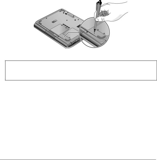
Resetting the Notebook
Occasionally, Windows or the notebook might stop responding, so that you cannot turn the notebook off. If this happens, try the following in the order listed. Press the power button to restart.
•If possible, shut down Windows:
Windows XP: press CTRL+ALT+DEL, and then click Shut Down, Restart.
Windows 2000: press CTRL+ALT+DEL, click Shut Down, and press the power button to restart.
•Press and hold the power button for about four seconds until the display shuts down, and then press the power button again to restart.
•Use a ball-point pen or a straightened paper clip to press the reset button on the bottom of the notebook.
Figure 1-4. Resetting the Notebook
Note
To boot from a CD, insert a bootable CD (such as the Recovery CDs) into the CD/DVD drive, then restart. Press Esc when the HP logo appears, then select the CD/DVD drive as the temporary boot device.
HP Omnibook XE4100/XE4500 |
Product Information |
1-9 |

Specifications
The following tables list the specifications for the notebook and its accessories. These are subject to change: for the latest versions, see the HP Notebook web site (www.hp.com/notebooks).
|
Table 1-7. Omnibook X4100 and XE4500 Specifications |
|
|
Physical Attributes |
Size (14-inch display): 328 × 272 × 33 mm (12.9 × 10.7 × 1.3 in). |
|
Size (15-inch display): 328 × 272 × 35 mm (12.9 × 10.7 × 1.4 in). |
|
Weight: 2.9 kg (6.5 lb) minimum, depending on configuration. |
|
|
Processor and |
Omnibook XE4500: |
Bus Architecture |
1.6- to 1.7-GHz Intel Mobile Pentium 4 processor-M with Intel Speed Step |
|
technology. |
|
512-KB L2 cache. |
|
1.2- to 1.3-V core low-power processor with 400-MHz processor system bus. |
|
Omnibook XE4100: |
|
1.13to 1.20-GHz Intel Mobile Celeron processor. |
|
256-KB L2 cache. |
|
1.45-V core low-power processor with 133-MHz processor system bus. |
|
|
Video |
14.1-inch XGA (1024 × 768), or 15.0-inch XGA (1024 × 768) or SXGA+ |
|
(1400 × 1050) active-matrix (TFT) LCD display. |
|
Hardware 3D acceleration, hardware DVD acceleration. |
|
Omnibook XE4500: |
|
External monitors up to 1600 × 1200 resolution, 16M colors, and at least 85 Hz |
|
refresh rate (only 60 Hz at 1400 × 1050). Refresh rate and clarity may vary |
|
depending on monitor, resolution, and color depth. |
|
ATI Mobility Radeon graphics accelerator with 16or 32-MB DDR graphics memory, |
|
4x AGP graphics capability. |
|
Dual display capability (depends on operating system support). |
|
Omnibook XE4100: |
|
External monitors up to 1600 × 1200 resolution with 16K colors at 60 Hz refresh rate |
|
or other resolutions at 64M colors and up to 85 Hz refresh rate. Refresh rate and |
|
clarity may vary depending on monitor, resolution, and color depth. |
|
VIA graphics with up to 32 MB dynamically allocated video RAM [16 MB (default) |
|
video RAM shared with system RAM]. |
|
|
Power |
Rechargeable lithium-ion (14.8 Vdc) or nickel-metal-hydride (9.6 Vdc) battery with |
|
LED charge-level gauge. |
|
Battery life: up to 3 (LiIon) or 2 hours (NiMH) hours typical (varies with model, usage, |
|
and power settings). |
|
Fast battery recharge: 2 hours when system is off, 3 hours when system is on. |
|
Low-battery warning. |
|
Suspend/resume capability. |
|
Omnibook XE4500: |
|
Universal AC adapter: 100–240 Vac (50/60 Hz) input, 19 Vdc output, 75 W. |
|
Omnibook XE4100: |
|
Universal AC adapter: 100–240 Vac (50/60 Hz) input, 19 Vdc output, 60 W (3.16 A) |
|
|
Mass Storage |
20to 40-GB removable hard drive with Ultra-DMA 100 interface. |
|
1.44-MB floppy drive (certain models). |
|
24x CD-ROM, or 8x DVD, or CD-RW, or CD-RW/DVD drive (or higher). |
|
|
1-10 Product Information |
HP Omnibook XE4100/XE4500 |

RAM |
At least 128 MB SDRAM preinstalled. |
|
Omnibook XE4500 |
|
Two slots for PC2100 DDR-266 SDRAM modules. |
|
Up to 2 GB (2048 MB) SDRAM using 1 GB modules (when available); otherwise, |
|
up to 1 GB (1024 MB) SDRAM using 512 MB modules. |
|
Omnibook XE4100 |
|
Two slots for PC-133 SDRAM modules. |
|
Up to 1 GB (1024 MB) SDRAM. |
|
|
Audio System |
Stereo sound via two built-in speakers. |
|
3D-enhanced audio. |
|
Volume and mute buttons (certain models). |
|
Headphone-out and microphone-in. |
|
|
Keyboard and |
87/88-key touch-type QWERTY keyboard with 101/102 key emulation. |
Pointing Device |
Embedded numeric keypad. |
|
12 function (Fn) keys. |
|
5 user-programmable One-Touch buttons. |
|
Touch pad with integrated scroll pad, on-off button and indicator. |
|
Left and right click buttons. |
|
|
LAN |
Ethernet 10Base-T (10 Mbps) and 100Base-TX (100 Mbps) support. |
(certain models) |
Supports wake-on-LAN, fast IP, DMI, dRMON. |
|
MBA (Managed Boot Agent) support for PXE/BINL, NCP/IPX, DHCP. |
|
|
Modem |
Software-based modem. |
(certain models) |
Data speed: 56 Kbps (V.92) maximum. |
|
Fax speed: 14.4 Kbps, Class 1 and 2. |
|
Modulation: V.21, V.22, V.22bis, V.23, V.32, V.32bis, V.34, V.90, V.92, X2, Bell 103, |
|
Bell 212A. |
|
Synchronous transfer: V.80. |
|
Compression: V.42bis, MNP5. |
|
Error correction: V.42, MNP2-4. |
|
Fax: Group 3 fax, Class 1. V.17, V.27ter, V.29, V.21. |
|
|
Wireless LAN |
Radio: IEEE 802.11b, WECA Wi-Fi compliant, direct-sequence spread-spectrum. |
(certain models) |
Operating frequency: 2.5-GHz ISM band, exact frequencies and channels depend on |
|
country. |
|
Raw data rate: 1, 2, 5.5, or 11 Mbps. |
|
Transmitter output: 15 dBm typical (approx. 30 mW), 16 dBm max (approx. 40 mW). |
|
Receiver sensitivity: –84 dBm typical. |
|
Range: up to 100 m (300 ft) or more, depending on environment and conditions. |
|
On-off button and indicator. |
|
Mini-PCI interface. |
|
|
Input/Output |
9-pin, 115,200-bps serial. |
|
25-pin bi-directional ECP/EPP parallel. |
|
15-pin VGA video-out with DDC support. |
|
S-video TV out (certain models). |
|
PS/2 keyboard/mouse. |
|
4-Mbps IrDA-compliant infrared port (certain models). |
|
IEEE-1394 (certain models). |
|
Universal serial bus (USB 1.1), two ports. |
|
|
Expandability |
One or two 16-/32-bit PC Card slots, Type II or III, CardBus enabled. |
|
Optional port replicator (certain models). |
|
|
Security Features |
User and administrator passwords. |
|
System password. |
|
PC identification displayed at boot. |
|
WMI-accessible electronic serial number. |
|
Kensington MicroSaver lock slot. |
|
|
HP Omnibook XE4100/XE4500 |
Product Information 1-11 |

Environmental Limits Operating temperature: 5 to 35 °C (41 to 95 °F).
|
Operating humidity: 20 to 90 percent RH (5 to 35 °C). |
|
Operating altitude: up to 3000 m (10,000 ft) at 25 °C (77 °F). |
|
Storage temperature: –20 to 50 °C (–4 to 122 °F). |
|
|
Major ICs |
Omnibook XE4500: |
|
CPU: Intel Mobile Pentium 4 processor-M. |
|
Core logic: ALI 1671 / 1535+ chipset. |
|
Display controller: ATI Mobility Radeon M6-C/P. |
|
Audio/Modem controller: Conexant Smart AMC CX20468-21. |
|
CardBus controller: TI PC1520. |
|
Keyboard/embedded controller: National PC87570. |
|
Super I/O: integrated in core logic. |
|
IEEE 1394: TI TSB43AB22. |
|
LAN: National NS83815. |
|
802.11b wireless LAN: Ambit with Intersil Prism 2.5 chipset. |
|
Omnibook XE4100: |
|
CPU: Intel Mobile Celeron processor. |
|
Core logic: VIA Twister-T + VT8231 chipset. |
|
Display controller: S3 Savage Pro integrated in core logic. |
|
Audio/Modem controller: Conexant Smart AMC CX20468-21. |
|
CardBus controller: O2Micro 6912. |
|
Keyboard/embedded controller: National PC87570. |
|
Super I/O: integrated in core logic. |
|
LAN: VIA Phy, MAC integrated in core logic. |
|
802.11b wireless LAN: Ambit with Intersil Prism 2.5 chipset. |
1-12 Product Information |
HP Omnibook XE4100/XE4500 |
Table 1-8. Omnibook XE4100, XE4500 Accessories
Accessory |
Description |
Omnibook |
Omnibook |
|
|
XE4500 |
XE4100 |
Memory |
|
|
|
F4694-60901 |
128MB DDR266B |
• |
|
F4695-60901 |
256MB DDR266B |
• |
|
F4696-60901 |
512MB DDR266B |
• |
|
1818-8504 |
SDRAM module, 128MB PC133 SODIMM (X16) |
|
• |
1818-8635 |
SDRAM module, 256MB PC133 SODIMM (X16) |
|
• |
1818-8604 |
SDRAM module, 512MB PC133 SODIMM (X8) |
|
• |
Hard Drives |
|
|
|
0950-4288 |
HDD-40GB 9.5mm, Toshiba ATA100 |
• |
• |
0950-4320 |
HDD-40.0GB 9.5mm, IBM ATA100 FDB |
• |
• |
Power Options |
|
|
|
0950-3988 |
AC-Adapter-Ultraslim 60W, 19V Output |
• |
|
F4600-60901 |
AC-Adapter-Ultraslim Delta 75W s/PFC |
|
• |
F4809-60901 |
Battery, LiIon 4.4AHr 8 Cell Li-Ion |
• |
• |
8120-6312 |
Cord, Pwr, Austr #ABG (2w) |
• |
• |
8120-8373 |
Cord, Pwr, China #AB2 (2w) |
• |
• |
8120-8373 |
Cord, Pwr, China #AB2 (2w) |
• |
• |
8120-6314 |
Cord, Pwr, Europe #ABB (2w) |
• |
• |
8120-6316 |
Cord, Pwr, Japan #ABJ (2w) |
• |
• |
8120-6317 |
Cord, Pwr, S.Afr #ACQ (2w) |
• |
• |
8120-8699 |
Cord, Pwr, UK (EPSR) For Hong Kong (2w) |
• |
• |
8120-6313 |
Cord, Pwr, US #ABA (2w) |
• |
• |
PC Cards |
|
|
|
F4640-60978 |
Card, mini-PCI-802.11B France |
• |
• |
F4640-60977 |
Card, mini-PCI-802.11B worldwide |
• |
• |
Docking |
|
|
|
F4808-60901 |
Port Replicator Assy |
• |
|
Adapter |
|
|
|
F1469A |
PS/2 Y adapter |
• |
• |
HP Omnibook XE4100/XE4500 |
Product Information 1-13 |

Internal Design
The motherboard PCA is the central component of the notebook’s design. It plays a role in virtually all system functions. The CPU module and most other subsystems connect to the motherboard.
The following figure shows the connections among the notebook’s replaceable electronic modules. Table 1-9 on page 1-15 lists the roles that these modules play in the notebook’s functional subsystems.
Figure 1-5. Replaceable Module Diagram
1-14 Product Information |
HP Omnibook XE4100/XE4500 |

Table 1-9. Functional Structure Description
Bootup |
CPU module |
Main processor (MMO). |
|
Motherboard |
Primary system circuitry, system BIOS. |
|
Hard disk drive |
First source of disk-based startup code. |
|
Floppy drive |
Second source of disk-based startup code. |
Processor |
CPU module |
Main processor, numeric data processor, L1 and L2 cache. |
|
Motherboard |
Primary system circuitry. |
Memory |
Motherboard |
Video RAM (XE4500). |
|
SDRAM module |
Changeable SDRAM (2 slots), video RAM (XE4100). |
|
|
no onboard SDRAM (XE4100/XE4500) |
Power |
Battery |
Power storage. |
|
Motherboard |
AC adapter socket, reset button, lid switch, power supply, power |
|
|
control circuitry. |
|
Switchboard PCA |
Power button |
|
AC adapter |
AC-to-DC converter. |
Display |
Motherboard |
Graphics controller, video RAM (XE4500) |
|
SDRAM module |
Shared video RAM (XE4100). |
|
Display assembly |
Display output, backlight, power converter for backlight. |
Hard disk |
Motherboard |
Hard disk controller. |
|
Hard disk drive |
Hard disk mechanism. |
Floppy drive |
Motherboard |
I/O controller, floppy connector. |
|
Floppy drive |
Floppy drive mechanism. |
Keyboard |
Motherboard |
Keyboard BIOS, keyboard controller. |
|
Switchboard PCA |
Power switch, one-touch buttons |
|
Keyboard |
Key switches. |
PS/2 |
Motherboard |
Keyboard circuitry, keyboard controller, keyboard BIOS. |
Touchpad |
Top case |
Touch pad sensor, click buttons, controller (PS/2 output). |
|
|
|
Audio |
Motherboard |
Audio controller, audio decoder, speaker amplifier, microphone, |
|
|
external audio jacks, headphone amplifier, audio-off switch. |
|
Speaker assembly |
Speakers. |
Status |
Motherboard |
LED circuitry, keyboard controller. |
|
Switchboard PCA |
Keyboard LEDs. |
|
Top case |
Main status LEDs. |
Serial |
Motherboard |
I/O controller, serial connector. |
|
|
|
Parallel |
Motherboard |
I/O controller, parallel connector. |
|
|
|
Infrared |
Motherboard |
I/O controller. |
|
IR PCA |
Infrared transmitter/receiver. |
PS/2 port |
Motherboard |
PS/2 connector, keyboard controller. |
USB |
Motherboard |
Bus controller (South Bridge), USB connector. |
|
|
|
S-Video |
Motherboard |
I/O controller, S-video connector (certain models). |
Port Replicator |
Motherboard |
Port replicator logic, port replicator connector (certain models). |
|
|
|
PCMCIA |
Motherboard |
PCMCIA controller. |
|
PCMCIA socket |
PCMCIA connectors. |
Wireless LAN |
Mini-PCI |
I/O controller, radio, radio frequency circuitry. |
(certain models) |
Antenna PCAs |
Transmit/receive antennas. |
|
IR PCA |
On/off switch, indicator light. |
LAN |
Motherboard |
LAN circuitry, bus controller, LAN connector. |
|
|
|
Modem |
Motherboard |
Modem circuitry (certain models), modem connector. |
HP Omnibook XE4100/XE4500 |
Product Information 1-15 |

2
Removal and Replacement
This chapter tells you how to remove and replace the notebook’s components and assemblies. The items marked by • in the following table are user-replaceable.
Table 2-1. Removal Cross-Reference
• Assembly, speaker (page 2-12). |
Drive, floppy (page 2-22). |
Battery, CMOS (page 2-37). |
• Drive, hard disk (page 2-7). |
• Battery, main (page 2-4). |
• Feet, rubber (page 2-9). |
• Card, wireless LAN mini-PCI (page 2-6). |
Heatsink (with fan) (page 2-27). |
Case, bottom (page 2-35). |
• Keyboard (page 2-13). |
Case, top (page 2-20). |
• Module, SDRAM (page 2-5). |
• Cover, keyboard (page 2-10). |
Module, CPU (page 2-29). |
Assembly, display (page 2-17). |
PCA, antennas (page 2-17). |
• Door, mini-PCI (page 2-9). |
PCA, I/R (page 2-25). |
• Door, SDRAM (page 2-9). |
PCA, motherboard (page 2-31). |
Doors, PCMCIA (page 2-35). |
PCA, switchboard (page 2-13). |
• Drive, CD/DVD (page 2-16). |
• Rubber screw plugs, display (page 2-9). |
|
|
Caution
Always provide proper grounding when performing repairs. Without proper grounding, an electrostatic discharge can damage the notebook and its components.
Notes
Reassembly steps are the reverse of the removal steps. Reassembly notes are included at the end of each section below.
 Symbols like these are displayed throughout this chapter to show approximate full-size screw outlines. You can use these to verify the sizes of screws before you install them. Installing a wrongsize screw can damage the notebook. (The symbol at the left represents an M2.5 × 4 mm T-head screw.)
HP Omnibook XE4100/XE4500 |
Removal and Replacement |
2-1 |

Table 2-2. Required Equipment
•Small Phillips screwdriver, preferably magnetized.
•Small flat-blade screwdriver.
•5 mm nut driver
Table 2-3. Recommended Screw Torque Values
Screw Thread Size |
Torque (cm-kgf) |
Torque (in-lbf) |
M2 |
2,0 – 2,5 |
1.7 – 2.2 |
M2.5 (hinges) |
3,5 – 4,0 |
3.0 – 3.4 |
M2.5 (other) |
2,5 – 3,0 |
2.2 – 2.6 |
M3 |
2,5 – 3,0 |
2.2 – 2.6 |
Standoff, hex |
2,5 – 3,0 |
2.2 – 2.6 |
2-2 |
Removal and Replacement |
HP Omnibook XE4100/XE4500 |

Disassembly Flowchart
The following diagram shows the general “path” you will use when disassembling the notebook to access any particular component.
Figure 2-1. Disassembly Flow
HP Omnibook XE4100/XE4500 |
Removal and Replacement |
2-3 |

Removing the Battery
(User-Replaceable)
Required Equipment
• None.
Removal Procedure
• Slide the battery’s release latch, then pull the battery out of its compartment.
Figure 2-2. Removing the Battery
2-4 |
Removal and Replacement |
HP Omnibook XE4100/XE4500 |

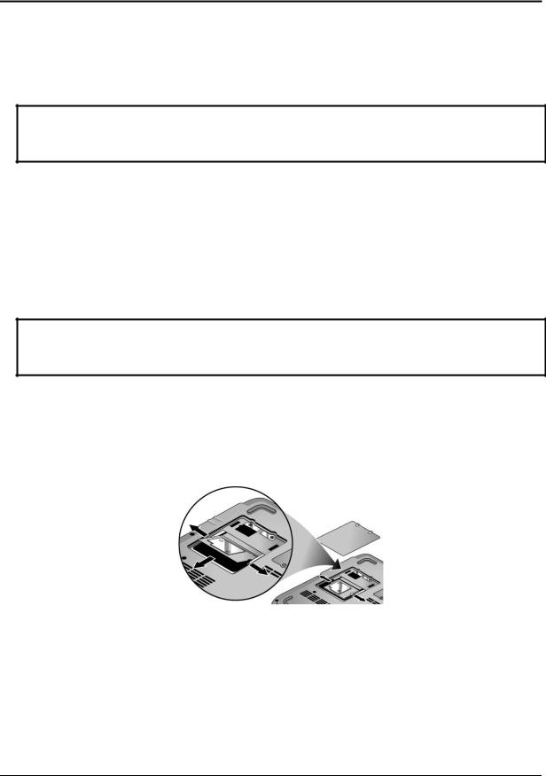
Removing a SDRAM Module
(User-Replaceable)
The notebook has no system memory built into its motherboard, but has two slots for SDRAM modules. One slot contains an SDRAM module that was factory installed.
Note
Omnibook XE4100 models use only PC133 SDRAM modules, and Omnibook XE4500 models use only DDR266 SDRAM modules. Using the wrong type of module prevents the notebook from booting.
Caution
Handle the SDRAM module only by its edges and provide proper grounding, or you might damage the module through electrostatic discharge.
Required Equipment
• Small Phillips screwdriver.
Removal Procedure
1.Unplug the AC adapter, if present, and then remove the battery.
2.On the bottom of the notebook, loosen the captive screws holding the SDRAM door, and then remove the door.
3.Press outward on the latches at the sides of the SDRAM module to release it (the SDRAM module pops up).
4.Carefully pull the SDRAM module out of the connector.
Figure 2-3. Removing an SDRAM Module
Reassembly Notes
•Carefully press the SDRAM module into the connector at an angle of about 30°, until it is fully inserted. Then press down on both sides of the SDRAM module until the latches snap closed.
HP Omnibook XE4100/XE4500 |
Removal and Replacement |
2-5 |
Removing the Wireless LAN Mini-PCI Card
(User-Replaceable)
Certain notebooks include a wireless LAN mini-PCI card under the mini-PCI door on the bottom of the notebook.
Caution
Handle the Mini-PCI card only by its edges and provide proper grounding, or you might damage the card through electrostatic discharge.
Required Equipment
• Small Phillips screwdriver.
Removal Procedure
1.Unplug the AC adapter, if present, and then remove the battery.
2.On the bottom of the notebook, loosen the captive screws holding the Mini-PCI door, and then remove the door.
Caution
Be careful when connecting and disconnecting the antenna cables from the mini-PCI card. Damaged cables or connectors can degrade notebook performance.
3.Disconnect the two antenna cables from the mini-PCI card.
4.Press outward on the latches at the sides of the mini-PCI card to release it (the mini-PCI card pops up).
5.Carefully pull the mini-PCI card out of the connector.
Figure 2-4. Removing the Mini-PCI Card
Reassembly Notes
•Carefully press the mini-PCI card into the connector at an angle of about 30°, until it is fully inserted. Then press down on both sides of the mini-PCI card until the latches snap closed.
2-6 |
Removal and Replacement |
HP Omnibook XE4100/XE4500 |
 Loading...