


 Loading...
HP Officejet Enterprise Color X555, Officejet Enterprise Color MFP X585 Repair Manual and Troubleshooting Manual
O cejet Enterprise Color X555
O cejet Enterprise Color MFP X585
Troubleshooting Manual
www.hp.com/support/ojcolorX555
www.hp.com/support/ojcolorMFPX585

HP Officejet Enterprise Color X555 and MFP
X585 Series
Troubleshooting Manual
Copyright and License
© 2014 Copyright Hewlett-Packard
Development Company, L.P.
Reproduction, adaptation, or translation without prior written permission is prohibited, except as allowed under the copyright laws.
The information contained herein is subject to change without notice.
The only warranties for HP products and services are set forth in the express warranty statements accompanying such products and services. Nothing herein should be construed as constituting an additional warranty. HP shall not be liable for technical or editorial errors or omissions contained herein.
Edition 1, 4/2014
Trademark Credits
Microsoft®, Windows®, Windows® XP, and Windows Vista® are U.S. registered trademarks of Microsoft Corporation.

Conventions used in this guide

 TIP: Tips provide helpful hints or shortcuts.
 NOTE: Notes provide important information to explain a concept or to complete a task.
CAUTION: Cautions indicate procedures that you should follow to avoid losing data or damaging the product.
WARNING! Warnings alert you to specific procedures that you should follow to avoid personal injury, catastrophic loss of data, or extensive damage to the product.
ENWW |
iii |
iv |
Conventions used in this guide |
ENWW |

Table of contents
1 Theory of operation ....................................................................................................................................... |
1 |
Basic operation ...................................................................................................................................................... |
2 |
Function structure ............................................................................................................................... |
2 |
Operation sequence ............................................................................................................................ |
4 |
System control ....................................................................................................................................................... |
7 |
Formatter and data path ..................................................................................................................... |
7 |
Engine control ..................................................................................................................................... |
8 |
Pen interface (I/F) .............................................................................................................................. |
10 |
Power supply ..................................................................................................................................... |
10 |
Print subsystem ................................................................................................................................................... |
12 |
Printbar .............................................................................................................................................. |
13 |
Printbar lift ........................................................................................................................................ |
14 |
Ink cartridges ..................................................................................................................................... |
15 |
Optical scan carriage ......................................................................................................................... |
15 |
Print system operational states ....................................................................................................... |
15 |
Paper-handling system ....................................................................................................................................... |
17 |
Input trays ......................................................................................................................................... |
24 |
Paper path zones .............................................................................................................................. |
24 |
Servicing system .................................................................................................................................................. |
28 |
Service sled ....................................................................................................................................... |
30 |
Aerosol management system ............................................................................................................................. |
31 |
Document feeder (X585 models) ........................................................................................................................ |
33 |
Document feeder operation .............................................................................................................. |
33 |
Document feeder paper path and sensors ....................................................................................... |
33 |
Document feeder jam detection ....................................................................................................... |
34 |
Scanner system (X585 models) .......................................................................................................................... |
35 |
Scanner power-on sequence of events ............................................................................................ |
35 |
Copy or scan-to-computer sequence of events ............................................................................... |
36 |
Fax functions and operation (X585 models) ....................................................................................................... |
37 |
Computer and network security features ........................................................................................ |
37 |
PSTN operation ................................................................................................................................. |
37 |
The fax subsystem ............................................................................................................................ |
37 |
ENWW |
v |
Fax card in the fax subsystem ................................................................................................. |
......... 37 |
Fax page storage in flash memory ................................................................................................... |
39 |
2 Solve problems ........................................................................................................................................... |
41 |
Problem-solving checklist ................................................................................................................................... |
42 |
Step 1: Check that the product power is on ...................................................................................... |
42 |
Step 2: Check the control panel for error messages ........................................................................ |
42 |
Step 3: Test print functionality ......................................................................................................... |
43 |
Step 4: Test copy functionality ......................................................................................................... |
43 |
Step 5: Test the fax sending functionality ........................................................................................ |
43 |
Step 6: Test the fax receiving functionality ...................................................................................... |
43 |
Step 7: Try sending a print job from a computer .............................................................................. |
43 |
Step 8: Test the Plug and Print USB Drive printing functionality ..................................................... |
44 |
Factors that affect product performance ......................................................................................... |
44 |
Troubleshooting process .................................................................................................................................... |
45 |
Determine the problem source ......................................................................................................... |
45 |
Power subsystem .............................................................................................................................. |
46 |
Scanning subsystem (X585) ............................................................................................................. |
47 |
Control panel checks ......................................................................................................................... |
47 |
Tools for troubleshooting ................................................................................................................................... |
57 |
Print the configuration page ............................................................................................................. |
57 |
Event log messages .......................................................................................................................... |
59 |
Error messages ................................................................................................................................. |
60 |
Individual component diagnostics .................................................................................................. |
149 |
Diagrams ......................................................................................................................................... |
154 |
Print-quality troubleshooting tools ............................................................................................... |
156 |
Preboot menu options .................................................................................................................... |
164 |
Control-panel menus ........................................................................................................................................ |
172 |
Administration menu ...................................................................................................................... |
172 |
Device Maintenance menu .............................................................................................................. |
233 |
Solve image quality problems .......................................................................................................................... |
236 |
Clean ink smears ............................................................................................................................. |
236 |
Recover the printhead .................................................................................................................... |
236 |
Solve paper jam or feed problems .................................................................................................................... |
237 |
Product does not pick up paper or misfeeds .................................................................................. |
237 |
Clear jams ........................................................................................................................................ |
238 |
Solve performance problems ............................................................................................................................ |
254 |
The product does not print ............................................................................................................. |
254 |
The product prints slowly ............................................................................................................... |
254 |
Solve connectivity problems ............................................................................................................................. |
256 |
Solve USB direct-connect problems ............................................................................................... |
256 |
vi |
ENWW |
Solve network problems ................................................................................................................. |
256 |
Solve wireless network problems .................................................................................................. |
257 |
Service mode functions ..................................................................................................................................... |
262 |
Service menu and Secondary service menu ................................................................................... |
262 |
Product resets ................................................................................................................................. |
262 |
Solve fax problems ............................................................................................................................................ |
263 |
Fax reports ...................................................................................................................................... |
263 |
Possible fax issues .......................................................................................................................... |
266 |
Product upgrades .............................................................................................................................................. |
275 |
Appendix A Service and support .................................................................................................................... |
277 |
Hewlett-Packard limited warranty statement ................................................................................................. |
278 |
UK, Ireland, and Malta ..................................................................................................................... |
279 |
Austria, Belgium, Germany, and Luxemburg .................................................................................. |
279 |
Belgium, France, and Luxemburg ................................................................................................... |
279 |
Italy .................................................................................................................................................. |
281 |
Spain ................................................................................................................................................ |
281 |
Denmark .......................................................................................................................................... |
281 |
Norway ............................................................................................................................................ |
281 |
Sweden ............................................................................................................................................ |
282 |
Portugal ........................................................................................................................................... |
282 |
Greece and Cyprus ........................................................................................................................... |
282 |
Hungary ........................................................................................................................................... |
282 |
Czech Republic ................................................................................................................................ |
282 |
Slovakia ........................................................................................................................................... |
283 |
Poland ............................................................................................................................................. |
283 |
Bulgaria ........................................................................................................................................... |
283 |
Romania .......................................................................................................................................... |
283 |
Belgium and The Netherlands ........................................................................................................ |
283 |
Finland ............................................................................................................................................. |
284 |
Slovenia ........................................................................................................................................... |
284 |
Croatia ............................................................................................................................................. |
284 |
Latvia ............................................................................................................................................... |
284 |
Lithuania .......................................................................................................................................... |
284 |
Estonia ............................................................................................................................................. |
285 |
End User License Agreement ............................................................................................................................ |
286 |
OpenSSL ............................................................................................................................................................. |
288 |
Customer self-repair warranty service ............................................................................................................. |
289 |
Customer support .............................................................................................................................................. |
290 |
ENWW |
vii |
Appendix B Product specifications ................................................................................................................. |
291 |
Physical specifications (X555 models) ............................................................................................................. |
292 |
Physical specifications (X585 models) ............................................................................................................. |
292 |
Power consumption, electrical specifications, and acoustic emissions .......................................................... |
292 |
Environmental specifications ............................................................................................................................ |
292 |
Appendix C Regulatory information ............................................................................................................... |
293 |
FCC regulations .................................................................................................................................................. |
294 |
Environmental product stewardship program ................................................................................................. |
295 |
Protecting the environment ........................................................................................................... |
295 |
Ozone production ............................................................................................................................ |
295 |
Power consumption ........................................................................................................................ |
295 |
Paper use ......................................................................................................................................... |
295 |
Plastics ............................................................................................................................................ |
295 |
HP Officejet print supplies .............................................................................................................. |
295 |
Return and recycling instructions ................................................................................................... |
296 |
Paper ............................................................................................................................................... |
297 |
Material restrictions ........................................................................................................................ |
297 |
Disposal of waste equipment by users ........................................................................................... |
297 |
Electronic hardware recycling ........................................................................................................ |
298 |
Chemical substances ....................................................................................................................... |
298 |
Material Safety Data Sheet (MSDS) ................................................................................................ |
298 |
EPEAT .............................................................................................................................................. |
298 |
For more information ...................................................................................................................... |
298 |
Declaration of conformity (X555 models) ........................................................................................................ |
299 |
Declaration of conformity (X585dn model) ...................................................................................................... |
301 |
Declaration of conformity (X585f and X585z models) ..................................................................................... |
303 |
Certificate of volatility (X555 models) .............................................................................................................. |
305 |
Certificate of volatility (X585 models) .............................................................................................................. |
307 |
Safety statements ............................................................................................................................................. |
309 |
Canada - Industry Canada ICES-003 Compliance Statement ......................................................... |
309 |
VCCI statement (Japan) ................................................................................................................... |
309 |
Power cord instructions .................................................................................................................. |
309 |
Power cord statement (Japan) ....................................................................................................... |
309 |
EMC statement (China) .................................................................................................................... |
309 |
EMC statement (Korea) ................................................................................................................... |
309 |
EMI statement (Taiwan) .................................................................................................................. |
310 |
GS statement (Germany) ................................................................................................................ |
311 |
Substances Table (China) ................................................................................................................ |
311 |
SEPA Ecolabel User Information (China) ........................................................................................ |
311 |
Restriction on Hazardous Substances statement (India) .............................................................. |
312 |
viii |
ENWW |
Restriction on Hazardous Substances statement (Turkey) ........................................................... |
312 |
Restriction on Hazardous Substances statement (Ukraine) .......................................................... |
312 |
Eurasian Conformity (Belarus, Kazakhstan, Russia) ...................................................................... |
312 |
Additional statements for telecom (fax) products ........................................................................................... |
313 |
EU Statement for Telecom Operation ............................................................................................ |
313 |
New Zealand Telecom Statements ................................................................................................. |
313 |
Additional FCC statement for telecom products (US) .................................................................... |
313 |
Telephone Consumer Protection Act (US) ...................................................................................... |
314 |
Industry Canada CS-03 requirements ............................................................................................ |
314 |
Vietnam Telecom wired/wireless marking for ICTQC Type approved products ............................ |
315 |
Japan Telecom Mark ....................................................................................................................... |
315 |
Index ........................................................................................................................................................... |
317 |
ENWW |
ix |
x |
ENWW |

List of tables
Table 1-1 |
Operation sequence ............................................................................................................................................. |
4 |
Table 1-2 Power supply module operating modes ............................................................................................................ |
11 |
|
Table 1-3 |
Printbar components ......................................................................................................................................... |
14 |
Table 1-4 |
Product sensors ................................................................................................................................................. |
20 |
Table 1-5 Paper-handling system motors ......................................................................................................................... |
23 |
|
Table 1-6 Paper path zones ............................................................................................................................................... |
26 |
|
Table 1-7 Service sled components ................................................................................................................................... |
30 |
|
Table 1-8 Aerosol management system components ...................................................................................................... |
32 |
|
Table 2-1 |
Troubleshooting flowchart ................................................................................................................................ |
45 |
Table 2-2 Control panel diagnostic functions .................................................................................................................... |
47 |
|
Table 2-3 Important information on the configuration pages .......................................................................................... |
59 |
|
Table 2-4 Heartbeat LED status ....................................................................................................................................... |
150 |
|
Table 2-5 Plug/jack locations (X555) ............................................................................................................................... |
154 |
|
Table 2-6 Plug/jack locations (X585) ............................................................................................................................... |
155 |
|
Table 2-7 Preboot menu options (1 of 6) ......................................................................................................................... |
165 |
|
Table 2-8 Preboot menu options (2 of 6) ......................................................................................................................... |
167 |
|
Table 2-9 Preboot menu options (3 of 6) ......................................................................................................................... |
168 |
|
Table 2-10 Preboot menu options (4 of 6) ...................................................................................................................... |
169 |
|
Table 2-11 Preboot menu options (5 of 6) ...................................................................................................................... |
169 |
|
Table 2-12 Preboot menu options (6 of 6) ...................................................................................................................... |
170 |
|
Table 2-13 Reports menu ................................................................................................................................................. |
172 |
|
Table 2-14 General Settings menu .................................................................................................................................. |
174 |
|
Table 2-15 Copy Settings menu (X585) ........................................................................................................................... |
179 |
|
Table 2-16 Scan/Digital Send Settings menu (X585) ...................................................................................................... |
185 |
|
Table 2-17 Fax Settings menu (X585) ............................................................................................................................. |
195 |
|
Table 2-18 General Print Settings menu ......................................................................................................................... |
207 |
|
Table 2-19 Print Options menu ........................................................................................................................................ |
210 |
|
Table 2-20 Display Settings menu ................................................................................................................................... |
211 |
|
Table 2-21 Manage Supplies menu .................................................................................................................................. |
213 |
|
Table 2-22 Manage Trays menu ....................................................................................................................................... |
217 |
|
Table 2-23 Network Settings menu ................................................................................................................................. |
219 |
|
Table 2-24 |
Jetdirect Menu ................................................................................................................................................ |
219 |
ENWW |
xi |
Table 2-25 Troubleshooting menu .................................................................................................................................. |
230 |
|
Table 2-26 Backup/Restore menu ................................................................................................................................... |
233 |
|
Table 2-27 |
Calibrate/Cleaning menu ............................................................................................................................... |
233 |
Table B-1 |
Physical specifications (X555 models), with ink cartridges ............................................................................ |
292 |
Table B-2 |
Physical specifications (X585 models), with ink cartridges ............................................................................ |
292 |
Table B-3 |
Operating-environment specifications ........................................................................................................... |
292 |
xii |
ENWW |

List of figures
Figure 1-1 Main components (X555 models) ....................................................................................................................... |
2 |
|
Figure 1-2 Main components (X585 models) ....................................................................................................................... |
3 |
|
Figure 1-3 |
System control .................................................................................................................................................... |
7 |
Figure 1-4 Print subsystem components (X555 models) .................................................................................................. |
12 |
|
Figure 1-5 Print subsystem components (X585 models) .................................................................................................. |
13 |
|
Figure 1-6 |
Printbar components ........................................................................................................................................ |
14 |
Figure 1-7 Paper-handling system paper path (X555 models) ......................................................................................... |
17 |
|
Figure 1-8 Paper-handling system paper path (X585 models) ......................................................................................... |
18 |
|
Figure 1-9 Product sensors (X555 models) ....................................................................................................................... |
19 |
|
Figure 1-10 Product sensors (X585 models) ..................................................................................................................... |
20 |
|
Figure 1-11 Paper-handling-system motors (X555 models) ............................................................................................ |
22 |
|
Figure 1-12 Paper-handling-system motors (X585 models) ............................................................................................ |
23 |
|
Figure 1-13 Paper path zones (X555 models) ................................................................................................................... |
25 |
|
Figure 1-14 Paper path zones (X585 models) ................................................................................................................... |
26 |
|
Figure 1-15 Servicing system components (X555 models) ............................................................................................... |
28 |
|
Figure 1-16 Servicing system components (X585 models) ............................................................................................... |
29 |
|
Figure 1-17 Service sled components ................................................................................................................................ |
30 |
|
Figure 1-18 Aerosol management process ........................................................................................................................ |
31 |
|
Figure 1-19 Aerosol management system components ................................................................................................... |
32 |
|
Figure 1-20 Document feeder paper path and sensors ..................................................................................................... |
34 |
|
Figure 2-1 Touchscreen blank, white, or dim (no image) .................................................................................................. |
51 |
|
Figure 2-2 Touchscreen is slow to respond or requires multiple presses to respond ...................................................... |
52 |
|
Figure 2-3 Touchscreen has an unresponsive zone .......................................................................................................... |
53 |
|
Figure 2-4 No control panel sound ..................................................................................................................................... |
54 |
|
Figure 2-5 |
Home button is unresponsive ..................................................................................................................... |
55 |
Figure 2-6 Hardware integration pocket (HIP) is not functioning (control panel functional) ........................................... |
56 |
|
Figure 2-7 |
Configuration page ........................................................................................................................................... |
57 |
Figure 2-8 HP embedded Jetdirect page ............................................................................................................................ |
58 |
|
Figure 2-9 |
LEDs ................................................................................................................................................................. |
149 |
Figure 2-10 Plug/jack locations (X555) ........................................................................................................................... |
154 |
|
Figure 2-11 Plug/jack locations (X585) ........................................................................................................................... |
155 |
|
Figure 2-12 Mark the web wipe ........................................................................................................................................ |
163 |
|
ENWW |
xiii |
Figure C-1 |
Certificate of volatility (X555 models) (1 of 2) ............................................................................................... |
305 |
Figure C-2 |
Certificate of volatility (X555 models) (2 of 2) ............................................................................................... |
306 |
Figure C-3 |
Certificate of volatility (X585 models) (1 of 2) ............................................................................................... |
307 |
Figure C-4 |
Certificate of volatility (X585 models) (2 of 2) ............................................................................................... |
308 |
xiv |
ENWW |

1 Theory of operation
●Basic operation
●System control
●Print subsystem
●Paper-handling system
●Servicing system
●Aerosol management system
●Document feeder (X585 models)
●Scanner system (X585 models)
●Fax functions and operation (X585 models)
ENWW |
1 |
Basic operation
Function structure
The product consists of the following components.
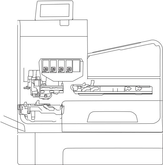
Figure 1-1 Main components (X555 models)
Control panel
Output bin
Optical scan carriage
Printbar
Service sled
Main input tray (Tray 2)
Multipurpose tray
(Tray 1) Duplex module\ 
 Waste ink module
Optional tray (Tray 3)
2 Chapter 1 Theory of operation |
ENWW |

Figure 1-2 Main components (X585 models)
Multipurpose tray (Tray 1)
Control panel
Document feeder
Scanner
Output bin
Optical scan carriage
Printbar
Service sled
Main input tray (Tray 2)
Duplex module\
Waste ink module
Optional tray (Tray 3)
The product contains the following systems:
●Engine control system
●Print subsystem
●Paper-handling system
●Servicing system
ENWW |
Basic operation 3 |

●Aerosol management system
●Scanner and document feeder system (X585 models) Two elements influence the product architecture:
●Orienting the printbar with its active face downward and statically located above the print media. This requires the printbar to move vertically to access its active face.
●Producing face-down output. Rather than ejecting the page face-up immediately after the ink is applied, as many inkjet printers do, the printed page is routed up and back over the printbar to eject face-down.
Operation sequence
The engine-control system on the formatter PCA controls the operational sequences. The following table describes durations and operations for each period of a print operation from when the product is turned on to when the motors stop rotating.
Table 1-1 Operation sequence
Period |
Duration |
Purpose |
|
|
|
|
|
Initial startup and |
When the product is set up for |
This period gets the product ready to print for the first time. |
|
calibrations |
the first time from the factory. |
● |
The product flushes the shipping and handling fluid out of the |
|
|
||
|
|
|
printbar and replaces it with ink. |
|
|
● |
Die alignment—The product aligns the 10 die on the printbar |
|
|
|
active face. |
|
|
● |
Die density leveling—The product measures and compensates |
|
|
|
for the drop variation. |
|
|
|
|
Servicing operations |
When the printbar is entering |
Servicing maintains the print quality by ensuring debris and excess |
|
|
the capping state after printing, |
ink are removed and missing nozzles are replaced. |
|
|
when leaving capping state after |
● |
Nozzle presence detection—The optical scan carriage detects |
|
a print job is initiated, or during |
||
|
extended print jobs. |
|
and disables inoperable nozzles, and replaces them with |
|
|
|
operable nozzles. |
|
|
● |
Printbar servicing—The web wipe on the service sled moves |
|
|
|
under the printbar to clean the active face and fire the nozzles |
|
|
|
into the waste ink module to clear clogs. |
|
|
|
|
4 Chapter 1 Theory of operation |
ENWW |
Table 1-1 Operation sequence (continued)
Period |
Duration |
Purpose |
|
|
|
|
|
Print preparation |
From the time the product |
Prepares the product for a print job. |
|
|
receives a print command until |
● |
The printbar leaves the capping state as the service sled |
|
paper enters the print zone. |
||
|
|
|
moves away from the printbar. |
|
|
● |
If needed, some servicing occurs. |
|
|
● |
The printbar lowers to the printing position. The media type |
|
|
|
and printing mode determine the print zone height. |
|
|
● |
The product picks media from one of the input trays. |
|
|
● |
Every page from Tray 1 is scanned. For Tray 2 and optional |
|
|
|
Tray 3, the product performs media edge detection after |
|
|
|
printing the first sheet after the main or optional tray is |
|
|
|
loaded. The last sheet of each job is also scanned if at least |
|
|
|
five sheets have been printed. |
|
|
● |
The product monitors environmental conditions. The product |
|
|
|
can decrease the print speed if conditions are significantly |
|
|
|
different from a normal office environment (23 degrees C (73 |
|
|
|
degrees F), 50% relative humidity). |
|
|
● |
The formatter PCA processes print data and transmits the data |
|
|
|
to the printbar. |
|
|
|
|
Printing |
From the end of the preparation |
Processes the print job. |
|
|
period until the last sheet is |
● |
As the page travels through the print zone, the printbar |
|
delivered. |
||
|
|
|
applies ink to the page. |
|
|
● |
Simplex print job: the page moves up, over the printbar, and |
|
|
|
out to the output bin (face-down). |
|
|
● |
Duplex print job: the page moves up until the trailing edge is |
|
|
|
40 mm past the star-wheel jam reflective sensor, then |
|
|
|
reverses direction down through the duplex path underneath |
|
|
|
the waste ink module, and then reenters the print zone where |
|
|
|
the printbar applies ink to the second side. |
|
|
● |
The process continues until all the pages of the print job are |
|
|
|
completed. Occasional nozzle presence detection and |
|
|
|
servicing events might occur if the job includes many pages. |
|
|
|
|
ENWW |
Basic operation 5 |

Table 1-1 Operation sequence (continued)
Period |
Duration |
Purpose |
End of print job |
Performed after the print job is |
|
completed, and continues until |
|
the next job is initiated. |
Puts the product in a state where it’s ready for the next print job.
●If needed, some servicing occurs.
●The printbar moves to the capping position after a short dwell interval.
●The service sled moves to cap the printbar.
Standby |
The product is sitting idle, |
|
waiting for the next print job to |
|
be initiated. |
Conserves energy while the product is sitting idle. Certain functions might be disabled to save power, then are restarted when needed. The product has three sleep modes:
●Idle mode—The printbar is capped and the product is ready to immediately start a new job
●Sleep1 mode—After the product is inactive for about 10 minutes, the control panel dims and the power LED blinks to indicate the unit is in Sleep1. All product functions are available. This setting can be adjusted from the control panel.
●Sleep2 mode—After the product is inactive for a longer period of time (typically 2 hours), the engine controller powers down to minimize power consumption. This setting can be adjusted from the control panel.
6 Chapter 1 Theory of operation |
ENWW |
System control
The system control coordinates all the other systems, according to commands from the formatter.
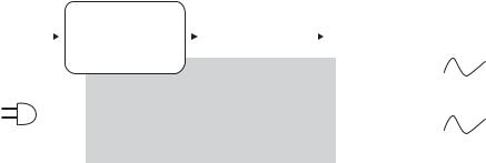
Figure 1-3 System control
I/O |
|
|
Formatter |
|
Datapath |
|
|
|
Pen I/F |
|
|
||||
|
|
|
|
|
|
|
|
|
ASIC +memory |
|
|
|
|
|
|
|
|
|
|
I/O, PDL, UI control |
|
|
|
|
• Pen energy control |
|
|
||||
|
|
|
|
|
|
|
|
|
|
|
|
|
|
|
|
|
|
|
|
|
|
|
|
|
|
|
|
|
|
||
|
|
|
|
|
|
|
|
|
|
|
|
|
• Pen voltage |
|
|
|
|
|
|
|
|
|
|
|
|
|
|
|
|
||
|
|
|
|
|
|
|
|
|
|
|
|
|
sequencing |
|
|
|
|
|
|
|
Power supply |
|
|
|
• Signal integrity |
|
Printbar |
||||
|
|
|
|
|
|
|
|
• Ink-short protection |
|
||||||
|
|
|
|
|
|
|
|
|
|
|
|
|
|
40,000 nozzles |
|
|
|
|
|
|
Scanner/ |
|
|
|
|
|
|
|
• Printhead |
|
|
|
|
|
|
|
|
|
|
Engine control |
|
|
|
interconnects |
|
|
|
|
|
|
document feeder |
|
|
|
|
|
|
• Ink supply |
|
|
|||
|
|
|
|
|
Motor + sensor drive |
|
|
|
|
|
|||||
|
|
|
|
(X585 models) |
|
|
|
|
|
|
|
|
|||
|
|
|
|
|
|
|
|
|
|
|
|
|
|
||
|
|
|
|
|
|
|
|
|
|
|
|
|
|
|
|
|
|
|
|
|
|
|
|
|
|
|
|
|
|
|
|
The system consists of the following major sections:
●Formatter
●Data path
●Engine control
●Pen interface
●Scanner/document feeder (X585 models)
●Power supply
The engine control electronics are located on the engine control board (ECB). The formatter PCA is a separate assembly. The fax module (X585 models) is attached to the formatter PCA.
Formatter and data path
The formatter controller ASIC controls the input/output (I/O) control, the user interface, and the rendering of page description language files into printer-specific commands.
Input/output (I/O) control
The products support 10/100 Ethernet, a rear USB host port, a rear USB device port, a control panel USB host port, and analog fax port (some X585 models). For Ethernet networks, the formatter PCA uses a separate integrated circuit (Broadcom 57761) to provide the physical network interface.
The formatter PCA also controls the USB device and USB host.
User interface
The products contain either a 4.2-in (X555 models) or an 8-in (X585 models) color graphics display. The control panels include a USB host port for connection to thumb drives.
Formatter digital ASIC
The formatter digital ASIC has an ARM CPÙ (792 MHz) that executes firmware code that provides high-level device control. The digital ASIC uses a standard PCle interface to pass data to the engine control ASIC. The
ENWW |
System control 7 |
formatter firmware is located on either a rotating hard disk drive (HDD) or, on some X555 models, a solid state drive (SSD).
Additionally, the formatter digital ASIC manages the real-time clock, interfaces to the mass storage controller ASIC, provides control of USB ports, and interfaces with the Ethernet LAN ASIC and fax module.
Formatter Ethernet ASIC
The formatter Ethernet ASIC connects to the formatter digital ASIC with a PCIe interface to transmit and receive network packets.
Formatter mass storage ASIC
The formatter mass storage ASIC bridges between the formatter digital ASIC (via PCIe interface) and the mass storage device (via SATA interface). Both HDD and SSD mass storage media are supported. The X585 models all use a rotating media HDD, while the X555 models use either HDD or SSD depending upon the bundle option.
Formatter memory
Formatter memory is installed on-board and there is no support for additional DIMM memory installation. The size of the memory on the formatter is fixed at 1 GB.
Real-time clock
The real-time clock (RTC) allows the fax module to time-stamp outgoing faxes. It also determines the elapsed time between printhead and ISS calibration events. The RTC uses a separate device connected to the formatter digital ASIC, along with a crystal and a battery.
Engine control
The engine controller digital ASIC receives high-level commands from the formatter, and then provides lowlevel control to the print mechanism. The engine controller digital ASIC and its firmware control motors, system sensors, and the printbar. The engine controller analog ASIC integrates motor drivers, voltage regulators, sensor interfaces, and supervisory circuits.
Engine controller digital ASIC
The engine controller digital ASIC has a high-performance 480 MHz ARM CPU and DSP co-processors that execute firmware code to provide low-level engine control. It also drives the printbar via 15 high-speed LVDS transmission lines, which are routed from the engine PCA to the printbar via two large FFC cables. The engine controller digital ASIC receives pre-rendered data from the formatter digital ASIC over a standard PCle interface.
In some product sleep modes, the digital ASIC powers down. If a print job is received while the product is in this mode, power resumes to the digital ASIC, which then must “boot up”. This can take approximately 15 seconds, which will delay the first page out (FPO) time accordingly. This sleep mode typically begins after two hours of product inactivity.
Engine controller analog ASIC
The engine uses two analog ASICs to generate the system voltages for the engine, drive the engine motors, control various engine sensors, and monitor printbar power delivery for correct operation.
The engine has seven motors, some of which are shared with other subsystems:
8 Chapter 1 Theory of operation |
ENWW |
●Pick motor
●Feed motor
●Duplex motor
●Lift motor
●Eject motor
●Sensor carriage motor
●Aerosol fan motor
Each one is a DC motor with encoder feedback, to provide precision servo control. These motors are driven directly by one of the engine analog ASICs. Small DC motors also are used to drive the ISS pump and the aerosol fan. Solenoids actuate the ejection flap and the ISS priming system.
The product uses many sensors to track the media as it travels through the paper path. Most of these are optical REDI sensors, which are used in conjunction with mirrors to sense the presence or absence of paper in a particular location. These are carefully aligned and calibrated at the factory, so care must be taken when servicing these sensors. See the Remove and Replace chapter in the repair manual for more details.
Other printed circuit-board assemblies (PCAs)
In addition to hosting the system ASICs, the engine PCA is home to many circuits needed to interface to sensors and other sub-system components. In some cases, this circuitry is located on a smaller remote PCA (SLB) to optimize cable interconnects.
●Humidity sensor—The humidity sensor causes the product to adjust printing speed if ambient conditions are outside the optimal humidity range. This sensor is calibrated at the factory to ensure maximum accuracy.
●Temperature sensor—The temperature sensor causes the product to adjust printing speed if ambient conditions are outside the optimal temperature range. In some products, this sensor resides on a separate, remote PCA.
●Main tray presence sensor—The hall-effect sensor that detects if the main tray is properly engaged resides on the back of the engine PCA. A small magnet on the back of the main tray actuates the sensor. If the tray is fully engaged, the magnetic field strength is sufficient to trigger the sensor.
Additionally, the product includes the following PCAs:
●Fax PCA—Governs the product fax module.
●Duplex module presence sensor—A hall-effect sensor that detects that the duplex module is properly seated.
●Power button PCA—Includes the power button and power LED, as well as interface cables to the duplex module presence sensor and the MP tray empty REDI sensor.
●Accessory tray interconnect PCA—Provides communication to optional Tray 3.
●Pick encoder distribution PCA—Includes the pick motor encoder and the pick motor interconnect cable.
●Eject encoder distribution PCA—Includes the eject motor encoder and the interconnect cables to the eject motor and the aerosol fan.
ENWW |
System control 9 |
●Print zone distribution PCA—Joins interconnect cables to the following sensors: separator REDI, feed motion encoder, main tray empty sensor, feed roller OOPs REDI sensor, and the starwheel jam REDI sensor.
●REDI distribution PCA—Includes hall-effect sensors that detect ink cartridge door and left door positions. It also combines the interconnect cables for the eject jam REDI sensor, the upper drying path REDI sensor, the lower drying path REDI sensor, and the eject flap opto flag sensor.
●Sensor carriage PCA—Includes a carriage motion encoder, a ZIM sensor, and the BDD sensor.
●Printbar lift encoder distribution PCA—This PCA includes the printbar lift motion encoder, and combines interconnect cables to the printbar lift motor, carriage motor, and eject flap solenoid.
●Duplex encoder PCA—Contains the motion encoder for the duplex motor.
●SHAID PCA —Contains interfaces to the out-of-ink sensors for the ink cartridges, and combines the interface cables to the acumen PCA, the ISS pump, and the ISS solenoids.
●Acumen PCA—Contains interfaces to the acumen memory devices for the ink cartridges.
Pen interface (I/F)
The printbar is the key component that differentiates this product from other inkjet printers. The conventional approach is to print a page in horizontal swaths by moving a “scanning” printhead horizontally over a fixed sheet of paper, advancing the paper a fixed amount, and then printing the next swath. With this product, the paper moves underneath a fixed page-wide printhead in a single smooth motion.
Single pass page-wide printing requires that data and power be delivered to the printbar at a very high rate, while also maintaining good control of paper position as it moves past the printhead nozzles.
The engine PCA sends power and data to the printbar via two large flat flexible cables (36 and 38 pins). The printbar PCA routes power and data to 10 printhead die, which are attached to the PCA using a flexible tab circuit and wire-bonding process.
Electronics control the ink supply station (ISS). The SHAID PCA detects low-ink conditions. It gauges ink levels by electrically sensing the presence of ink and/or ink foam in the X-chamber. The SHAID PCA also collects and distributes electrical signals that drive the push-prime pump(s), engage the solenoids, and read the ink supply acumen data. All are routed through a single 17-pin FFC from the SHAID PCA to the engine PCA.
Each ink supply has a memory tag that stores information about its type of ink, the amount of ink remaining, and other critical data. It uses a special authentication scheme to ensure that only genuine HP supplies are used and the product is not damaged by using invalid supplies. Acumen uses a two-line serial bus, which, along with 3.3 V and ground, is cabled via the SHAID PCA to the engine PCA and the engine control digital ASIC.
Power supply
The power supply module converts 100-240 VAC to 33 VCD and 5.1 VCD to power the system. The 33 V rail goes to the engine and the scanner/document feeder, and the 5.1 V rail is supplies power to the formatter. The power supply module has a sleep mode that reduces power consumption in system low-power modes.
The power supply module has four operating modes, depending on certain control signals, as outlined in the table below. The power supply has a power factor correction (PFC) circuit to improve efficiency when the system is in the active mode.
10 Chapter 1 Theory of operation |
ENWW |

Table 1-2 Power supply module operating modes
Mode |
n33V_OFF input signal |
nPFC_OFF input signal |
PFC Status |
33 V rail status |
5.1 V rail status |
|
|
|
|
|
|
OFF |
Low |
Low |
Off |
Off |
On |
|
|
|
|
|
|
Sleep 2 |
Low |
Low |
Off |
Off |
On |
|
|
|
|
|
|
Sleep 1 |
High |
Low |
Off |
On |
On |
|
|
|
|
|
|
Active |
High |
High |
On |
On |
On |
|
|
|
|
|
|
The power supply is a self-contained module that can be replaced if it is defective (see the Remove and Replace chapter of the Repair Manual).
To ensure safe operation, the power supply will “latch off” if a persistent over-current fault condition exists. This is typically caused by a short-circuit from 33 V or 5.1 V to ground in the product. Less severe faults also can cause the power supply to latch off, if present for an extended period of time, or if the product is operated above the recommended operating range.
ENWW |
System control 11 |
Print subsystem
The print subsystem includes the following components:
●Printbar
●Printbar lift
●Ink cartridges
●Optical scan carriage
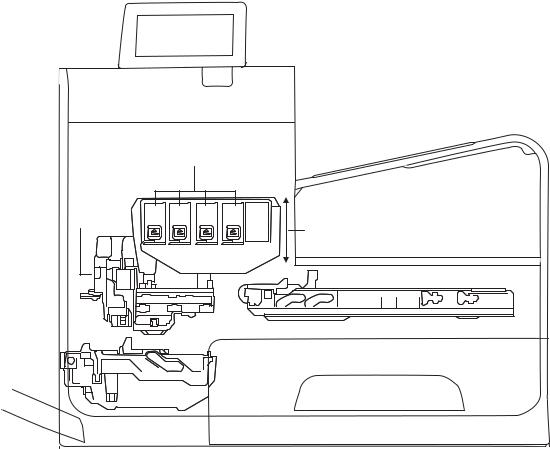
Figure 1-4 Print subsystem components (X555 models)
Ink cartridges
Optical scan
carriage
Printbar lift
Printbar
12 Chapter 1 Theory of operation |
ENWW |
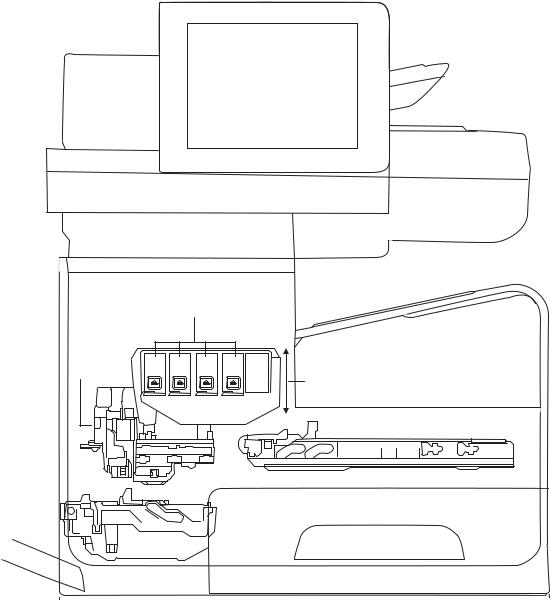
Figure 1-5 Print subsystem components (X585 models)
Ink cartridges
Optical scan
carriage
Printbar lift
Printbar
Printbar
The printbar converts the digital firing instructions from the product electronics into properly formed and timed microscopic drops of the four ink colors. The printbar spans the full width of a letter/A4-size sheet (216 mm (8.5 in)), which allows it to be statically positioned within the product and have the media move underneath it, printing the entire page in a single motion.
ENWW |
Print subsystem 13 |
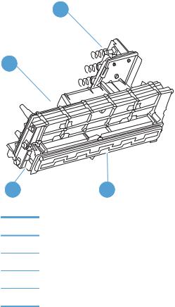
Figure 1-6 Printbar components
1
4
3 2
Table 1-3 Printbar components
Item Description
1Ink cartridge connections
2Thermal inkjet (TIJ) die array
3Data/power flow and regulation
4Inkflow channels and pressure regulation
The printbar has a fixed array of 10 thermal inkjet (TIJ) die oriented in two staggered rows. Each die contains over one thousand nozzles for each of the four ink colors (black (K), cyan (C), magenta (M) and yellow (Y)). Behind the die array are the ink flow channels and pressure regulation mechanisms that supply the die array with ink at the proper pressure and flow. Onboard electronic circuitry feeds power and data to the die at the appropriate levels and rates. Four ink cartridge receptacles, one for each color, are located at the top of the printbar. Flow connections link these cartridges to the rest of the printbar to supply the ink necessary for its operation.
A sensor technology called back-scatter drop detect (BDD) monitors printbar health and calibrations. This system looks at the reflection of the miniscule drops in flight and passes these signals through proprietary, advanced high-speed, high-gain, bandpass filters. An artificial intelligence (AI) system decides which drop ejectors are currently in or out of specifications.
After the AI system determines which drop ejectors are out of specification, the product compensates for them. Some ejectors use neighboring nozzles and at times even tiny amounts of other inks – whichever combination of methods necessary to deliver the best print quality possible at that moment. Up to half of the nozzles can be “out” without a noticeable degradation in quality. The compensation is done in real time with a dedicated high-speed DSP. The system can scan portions of the system after print jobs, but it is fully interruptible by new incoming print jobs.
Printbar lift
The printbar lift positions the printbar within the product and moves it up and down as required. This vertical motion establishes proper spacing to the paper during printing. It also raises the printbar to access the active face or perform necessary calibrations.
14 Chapter 1 Theory of operation |
ENWW |
Loading...