


 Loading...
HP Officejet Enterprise Color X555, Officejet Enterprise Color MFP X585 Repair Manual and Troubleshooting Manual
O cejet Enterprise Color X555
O cejet Enterprise Color MFP X585
Repair Manual
www.hp.com/support/ojcolorX555
www.hp.com/support/ojcolorMFPX585

HP Officejet Enterprise Color X555 and MFP
X585 Series
Repair Manual
Copyright and License
© 2014 Copyright Hewlett-Packard
Development Company, L.P.
Reproduction, adaptation, or translation without prior written permission is prohibited, except as allowed under the copyright laws.
The information contained herein is subject to change without notice.
The only warranties for HP products and services are set forth in the express warranty statements accompanying such products and services. Nothing herein should be construed as constituting an additional warranty. HP shall not be liable for technical or editorial errors or omissions contained herein.
Edition 1, 4/2014
Trademark Credits
Microsoft®, Windows®, Windows® XP, and Windows Vista® are U.S. registered trademarks of Microsoft Corporation.

Conventions used in this guide

 TIP: Tips provide helpful hints or shortcuts.
 NOTE: Notes provide important information to explain a concept or to complete a task.
CAUTION: Cautions indicate procedures that you should follow to avoid losing data or damaging the product.
WARNING! Warnings alert you to specific procedures that you should follow to avoid personal injury, catastrophic loss of data, or extensive damage to the product.
ENWW |
iii |
iv |
Conventions used in this guide |
ENWW |

Table of contents
1 Removal and replacement .............................................................................................................................. |
1 |
Removal and replacement strategy ...................................................................................................................... |
2 |
Electrostatic discharge ........................................................................................................................ |
2 |
Required tools ..................................................................................................................................... |
3 |
Types of screws ................................................................................................................................... |
3 |
Service approach ................................................................................................................................................... |
3 |
Before performing service .................................................................................................................. |
3 |
After performing service ..................................................................................................................... |
3 |
Post-service test ................................................................................................................................. |
4 |
Removal and replacement procedures ................................................................................................................. |
5 |
Customer replaceable parts ................................................................................................................ |
5 |
Covers ................................................................................................................................................ |
33 |
Main assemblies ................................................................................................................................ |
44 |
2 Parts and diagrams ...................................................................................................................................... |
63 |
Order parts by authorized service providers ...................................................................................................... |
64 |
Order replacement parts ................................................................................................................... |
64 |
Related documentation and software .............................................................................................. |
64 |
Supplies part numbers ...................................................................................................................... |
64 |
Customer self-repair parts ............................................................................................................... |
65 |
How to use the parts lists and diagrams ............................................................................................................. |
68 |
Assembly locations—X555 models .................................................................................................................... |
69 |
Assembly locations—X585 models .................................................................................................................... |
70 |
Covers, control panels, and doors—X555 models ............................................................................................. |
72 |
Covers, control panels, and doors—X585 models ............................................................................................. |
74 |
Internal assemblies—all models ........................................................................................................................ |
76 |
Scanner/document feeder assembly—X585 models ........................................................................................ |
80 |
Alphabetical parts list .......................................................................................................................................... |
82 |
Numerical parts list ............................................................................................................................................. |
86 |
Index ............................................................................................................................................................. |
91 |
ENWW |
v |
vi |
ENWW |

List of tables
Table 2-1 Order parts, accessories, and supplies .............................................................................................................. |
64 |
|
Table 2-2 Related documentation and software ............................................................................................................... |
64 |
|
Table 2-3 Supplies part numbers ....................................................................................................................................... |
64 |
|
Table 2-4 |
Product accessories ........................................................................................................................................... |
65 |
Table 2-5 Customer self-repair parts ................................................................................................................................ |
65 |
|
Table 2-6 Assembly locations—X555 models .................................................................................................................. |
69 |
|
Table 2-7 |
Assembly locations—X585 models .................................................................................................................. |
70 |
Table 2-8 |
Covers, control panels, and doors—X555 models ........................................................................................... |
73 |
Table 2-9 |
Covers, control panels, and doors—X585 models ........................................................................................... |
75 |
Table 2-10 |
Internal assemblies .......................................................................................................................................... |
77 |
Table 2-11 Internal assemblies—print mechanism kit ..................................................................................................... |
79 |
|
Table 2-12 Scanner/document feeder assembly—X585 models ..................................................................................... |
81 |
|
Table 2-13 |
Alphabetical parts list ...................................................................................................................................... |
82 |
Table 2-14 |
Numerical parts list .......................................................................................................................................... |
86 |
ENWW |
vii |
viii |
ENWW |
List of figures
Figure 1-1 Remove Tray 2 .................................................................................................................................................... |
5 |
Figure 1-2 Remove the ink collection unit (1 of 2) ............................................................................................................... |
7 |
Figure 1-3 Remove the ink collection unit (2 of 2) ............................................................................................................... |
7 |
Figure 1-4 Remove the output bin ....................................................................................................................................... |
8 |
Figure 1-5 Remove the output bin flap ................................................................................................................................ |
9 |
Figure 1-6 Remove the document-feeder roller (1 of 3) ................................................................................................... |
10 |
Figure 1-7 Remove the document-feeder roller (2 of 3) ................................................................................................... |
10 |
Figure 1-8 Remove the document-feeder roller (3 of 3) ................................................................................................... |
11 |
Figure 1-9 Reinstall the document-feeder roller .............................................................................................................. |
11 |
Figure 1-10 Remove the document-feeder separation pad spring (1 of 3) ...................................................................... |
12 |
Figure 1-11 Remove the document-feeder separation pad spring (2 of 3) ...................................................................... |
12 |
Figure 1-12 Remove the document feeder separation pad spring (3 of 3) ....................................................................... |
13 |
Figure 1-13 Remove the document feeder white backing (1 of 3) .................................................................................... |
14 |
Figure 1-14 Remove the document feeder white backing (2 of 3) .................................................................................... |
14 |
Figure 1-15 Remove the document feeder white backing (3 of 3) .................................................................................... |
15 |
Figure 1-16 Install a replacement document feeder white backing (1 of 6) ..................................................................... |
15 |
Figure 1-17 Install a replacement document feeder white backing (2 of 6) ..................................................................... |
16 |
Figure 1-18 Install a replacement document feeder white backing (3 of 6) ..................................................................... |
16 |
Figure 1-19 Install a replacement document feeder white backing (4 of 6) ..................................................................... |
17 |
Figure 1-20 Install a replacement document feeder white backing (5 of 6) ..................................................................... |
17 |
Figure 1-21 Install a replacement document feeder white backing (6 of 6) ..................................................................... |
18 |
Figure 1-22 Remove the background selector (1 of 4) ...................................................................................................... |
19 |
Figure 1-23 Remove the background selector (2 of 4) ...................................................................................................... |
19 |
Figure 1-24 Remove the background selector (3 of 4) ...................................................................................................... |
20 |
Figure 1-25 Remove the background selector (4 of 4) ...................................................................................................... |
20 |
Figure 1-26 Reinstall the background selector ................................................................................................................. |
21 |
Figure 1-27 Remove the control panel — X555 models (1 of 4) ...................................................................................... |
21 |
Figure 1-28 Remove the control panel — X555 models (2 of 4) ...................................................................................... |
22 |
Figure 1-29 Remove the control panel — X555 models (3 of 4) ...................................................................................... |
22 |
Figure 1-30 Remove the control panel — X555 models (4 of 4) ...................................................................................... |
23 |
Figure 1-31 Remove the control panel — X585 models (1 of 4) ...................................................................................... |
23 |
Figure 1-32 Remove the control panel — X585 models (2 of 4) ...................................................................................... |
24 |
ENWW |
ix |
Figure 1-33 Remove the control panel — X585 models (3 of 4) ...................................................................................... |
24 |
Figure 1-34 Remove the control panel — X585 models (4 of 4) ...................................................................................... |
25 |
Figure 1-35 Remove the control panel keyboard — X585 Flow models (1 of 2) ............................................................. |
25 |
Figure 1-36 Remove the control panel keyboard — X585 Flow models (2 of 2) ............................................................. |
26 |
Figure 1-37 Remove the formatter PCA (1 of 3) ................................................................................................................ |
27 |
Figure 1-38 Remove the formatter PCA (2 of 3) ................................................................................................................ |
27 |
Figure 1-39 Remove the formatter PCA (3 of 3) ................................................................................................................ |
28 |
Figure 1-40 Remove the fax PCA (1 of 2) ........................................................................................................................... |
28 |
Figure 1-41 Remove the fax PCA (2 of 2) ........................................................................................................................... |
29 |
Figure 1-42 Remove the SSD (1 of 2) ................................................................................................................................. |
29 |
Figure 1-43 Remove the SSD (2 of 2) ................................................................................................................................. |
30 |
Figure 1-44 Remove the HDD ............................................................................................................................................. |
30 |
Figure 1-45 Remove the rear cover (1 of 2) ....................................................................................................................... |
33 |
Figure 1-46 Remove the rear cover (2 of 2) ....................................................................................................................... |
33 |
Figure 1-47 Remove left door (1 of 5) ................................................................................................................................ |
34 |
Figure 1-48 Remove the left door (2 of 5) ......................................................................................................................... |
34 |
Figure 1-49 Remove the left door (3 of 5) ......................................................................................................................... |
35 |
Figure 1-50 Remove the left door (4 of 5) ......................................................................................................................... |
35 |
Figure 1-51 Remove the left door (5 of 5) ......................................................................................................................... |
36 |
Figure 1-52 Remove the left rear cover (1 of 2) ................................................................................................................ |
36 |
Figure 1-53 Remove the left rear cover (2 of 2) ................................................................................................................ |
37 |
Figure 1-54 Remove the left front cover (1 of 2) ............................................................................................................... |
37 |
Figure 1-55 Remove the left front cover (2 of 2) ............................................................................................................... |
38 |
Figure 1-56 Remove the top cover (1 of 4) ........................................................................................................................ |
39 |
Figure 1-57 Remove the top cover (2 of 4) ........................................................................................................................ |
39 |
Figure 1-58 Remove the top cover (3 of 4) ........................................................................................................................ |
40 |
Figure 1-59 Remove the top cover (4 of 4) ........................................................................................................................ |
40 |
Figure 1-60 Remove the top cover cap (1 of 2) ................................................................................................................. |
41 |
Figure 1-61 Remove the top cover cap (2 of 2) ................................................................................................................. |
41 |
Figure 1-62 Remove the front cover (1 of 2) ..................................................................................................................... |
42 |
Figure 1-63 Remove the front cover (2 of 2) ..................................................................................................................... |
42 |
Figure 1-64 Remove the right cover (1 of 2) ...................................................................................................................... |
43 |
Figure 1-65 Remove the right cover (2 of 2) ...................................................................................................................... |
43 |
Figure 1-66 Remove the document feeder mylar strip (1 of 4) ......................................................................................... |
44 |
Figure 1-67 Remove the document feeder mylar strip (2 of 4) ......................................................................................... |
44 |
Figure 1-68 Remove the document feeder mylar strip (3 of 4) ......................................................................................... |
45 |
Figure 1-69 Remove the document feeder mylar strip (4 of 4) ......................................................................................... |
45 |
Figure 1-70 Install a replacement document feeder mylar strip (1 of 2) ......................................................................... |
46 |
Figure 1-71 Install a replacement document feeder mylar strip (2 of 2) ......................................................................... |
46 |
Figure 1-72 Remove the document feeder (1 of 6) ........................................................................................................... |
47 |
Figure 1-73 Remove the document feeder (2 of 6) ........................................................................................................... |
47 |
x |
ENWW |
Figure 1-74 Remove the document feeder (3 of 6) ........................................................................................................... |
48 |
Figure 1-75 Remove the document feeder (4 of 6) ........................................................................................................... |
48 |
Figure 1-76 Remove the document feeder (5 of 6) ........................................................................................................... |
49 |
Figure 1-77 Remove the document feeder (6 of 6) ........................................................................................................... |
49 |
Figure 1-78 Remove the SCB (1 of 6) ................................................................................................................................. |
50 |
Figure 1-79 Remove the SCB (2 of 6) ................................................................................................................................. |
50 |
Figure 1-80 Remove the SCB (3 of 6) ................................................................................................................................. |
51 |
Figure 1-81 Remove the SCB (4 of 6) ................................................................................................................................. |
51 |
Figure 1-82 Remove the SCB (5 of 6) ................................................................................................................................. |
52 |
Figure 1-83 Remove the SCB (6 of 6) ................................................................................................................................. |
52 |
Figure 1-84 Remove the scanner (1 of 7) ........................................................................................................................... |
53 |
Figure 1-85 Remove the scanner (2 of 7) ........................................................................................................................... |
53 |
Figure 1-86 Remove the scanner (3 of 7) ........................................................................................................................... |
54 |
Figure 1-87 Remove the scanner (4 of 7) ........................................................................................................................... |
54 |
Figure 1-88 Remove the scanner (5 of 7) ........................................................................................................................... |
55 |
Figure 1-89 Remove the scanner (6 of 7) ........................................................................................................................... |
55 |
Figure 1-90 Remove the scanner (7 of 7) ........................................................................................................................... |
56 |
Figure 1-91 Remove the power supply (1 of 3) ................................................................................................................. |
56 |
Figure 1-92 Remove the power supply (2 of 3) ................................................................................................................. |
57 |
Figure 1-93 Remove the power supply (3 of 3) ................................................................................................................. |
57 |
Figure 2-1 Assembly locations—X555 models ................................................................................................................. |
69 |
Figure 2-2 Assembly locations—X585 models ................................................................................................................. |
70 |
Figure 2-3 Covers, control panels, and doors—X555 models .......................................................................................... |
72 |
Figure 2-4 Covers, control panels, and doors—X585 models .......................................................................................... |
74 |
Figure 2-5 Internal assemblies ........................................................................................................................................... |
76 |
Figure 2-6 Internal assemblies—print mechanism kit ...................................................................................................... |
78 |
Figure 2-7 Scanner/document feeder assembly—X585 models ..................................................................................... |
80 |
ENWW |
xi |
xii |
ENWW |

1 Removal and replacement
●Removal and replacement strategy
●Service approach
●Removal and replacement procedures
ENWW |
1 |

Removal and replacement strategy
 WARNING! Turn the product off, wait 5 seconds, and then remove the power cord before attempting to service the product. If this warning is not followed, severe injury can result, in addition to damage to the product. The power must be on for certain functional checks during problem solving. However, the power supply should be disconnected during parts removal.
The sheet-metal parts can have sharp edges. Be careful when handling sheet-metal parts.
CAUTION: Many repair operations will require you to flatten or straighten flex cables. However, where possible, try to avoid doing so. You must make sure that all FFCs are fully seated in their connectors. Failure to fully seat an FFC into a connector can cause a short circuit in a printed circuit-board assembly (PCA).


 NOTE: To install a self-tapping screw, first turn it counterclockwise to align it with the existing thread pattern, and then carefully turn it clockwise to tighten. Do not overtighten. If a self-tapping screw-hole becomes stripped, repair the screw-hole or replace the affected assembly.
Throughout this chapter, the reinstallation process should follow the reverse order of the removal process documented. Where necessary, the tasks include reinstallation tips to aid in the installation of replacement parts.
Electrostatic discharge
 CAUTION:
  Some parts are sensitive to electrostatic discharge (ESD). Look for the ESD reminder when
removing product parts. Always perform service work at an ESD-protected workstation or mat. If an ESD workstation or mat is not available, ground yourself by touching the sheet-metal chassis before touching an ESD-sensitive part.
Protect the ESD-sensitive parts by placing them in ESD pouches when they are out of the product.
2 Chapter 1 Removal and replacement |
ENWW |

Required tools
●#T10 TORX driver with a magnetic tip and a 152 mm (6 in) shaft length
●Small flatblade screwdriver
●Needle-nose pliers
●ESD mat (if one is available) or ESD strap
●Penlight (optional)
Types of screws
 WARNING! Make sure that components are replaced with the correct screw type. Using the incorrect screw (for example, substituting a long screw for the correct shorter screw) can cause damage to the product or interfere with product operation. Do not intermix screws that are removed from one component with the screws that are removed from another component.
Service approach
 CAUTION: When working on the product, do not pick up the unit by the output tray, which will detach under the weight of the product.
Before performing service
●Remove all paper from the product.
●Turn off the power using the power button.
●Unplug the power cable and interface cable or cables.
●Remove the output bin.
●Place the product on an ESD workstation or mat, or use an ESD strap (if one is available). If an ESD workstation, mat, or strap is not available, ground yourself by touching the sheet-metal chassis before touching an ESD-sensitive part.
●Remove the ink cartridges.
●Remove the Tray 2 cassette.
●Remove the ink collection unit, which is located inside the left door.


 NOTE: When removing the ink collection unit, avoid making direct contact with the black cylinder to prevent ink smear on skin or clothes. Keep the ink collection unit level to avoid spilling any waste ink.
After performing service
●Plug in the power cable.
●Reinstall the output bin.
●Reinstall the ink cartridges.
●Reinstall the Tray 2 cassette.
ENWW |
Service approach 3 |
●Reinstall the ink collection unit.
●Load paper in the product.
Post-service test
Perform the following test to verify that the repair or replacement was successful.
Print-quality test
1.Verify that you have completed the necessary reassembly steps.
2.Make sure that the tray contains clean, unmarked paper.
3.Attach the power cord and interface cable or interface cables, and then turn on the product.
4.Print a configuration page.
5.Print a print quality page, and then verify that there are no lines, streaks, banding, or other print quality defects.
6.Send a print job from the host computer, and then verify that the output meets expectations.
7.Clean the outside of the product with a damp cloth.
4 Chapter 1 Removal and replacement |
ENWW |
Removal and replacement procedures


 NOTE: Due to time constraints in producing this manual, the product might look slightly different than what is depicted in the photographs in this section. Most changes will be cosmetic in nature and should not affect the repair procedures.
Customer replaceable parts
CSR-A parts
CSR-A parts require no tools during installation.
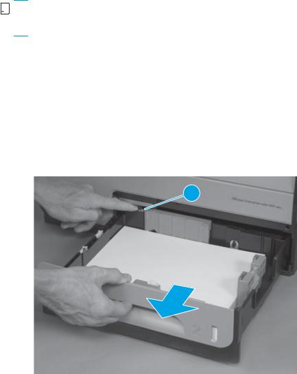
Tray 2
▲Pull out the tray, and then press the latch (callout 1) in left-rear corner of the tray to remove it from the product.
Figure 1-1 Remove Tray 2
1
Ink cartridges
The product uses four colors and has a different ink cartridge for each color: yellow (Y), cyan (C), magenta (M), and black (K).
ENWW |
Removal and replacement procedures 5 |
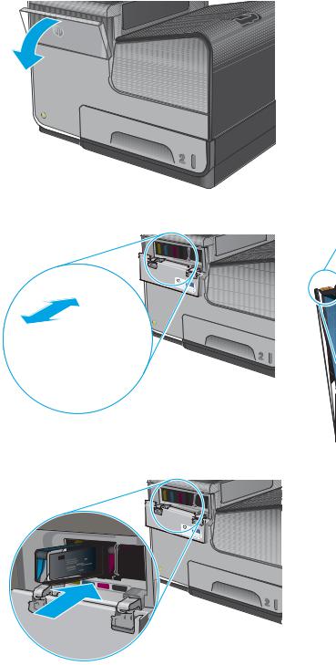
1.Open the ink cartridge door.
2.Push the old ink cartridge inward to unlock it, and then pull the cartridge straight out to remove it.
CAUTION: When handling the new ink cartridges, do not touch the gold-colored metal contacts on the cartridges. Fingerprints on the contacts can cause print-quality problems.
3.Insert the new ink cartridge into the product, push the cartridge until it “clicks” into place, and then close the ink cartridge door.
4.Place the old cartridge in the box. Refer to the box for information about recycling used ink cartridges.
6 Chapter 1 Removal and replacement |
ENWW |
Ink collection unit
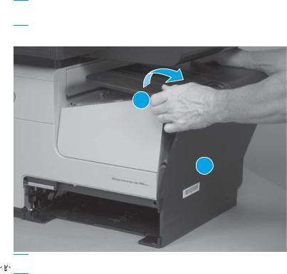
1.Open the left door.
Figure 1-2 Remove the ink collection unit (1 of 2)
2.Use the green hand-grip to pull the ink collection unit out of the product.


 NOTE: When removing the ink collection unit, avoid making direct contact with the black cylinder to prevent ink smear on skin or clothes. Keep the ink collection unit level to avoid spilling any waste ink.
Also, do not let the bottom of the ink collection unit touch or rest on the ribs on the left door, which can damage them and might lead to media damage and jams.
Figure 1-3 Remove the ink collection unit (2 of 2)
ENWW |
Removal and replacement procedures 7 |
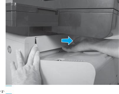
Output bin
▲Lift and unsnap the output bin tabs below the output flap, and then lift the output bin to remove it from the product.
 CAUTION: Do not tilt the assembly too far back, as it will damage tabs at bottom seam of the output bin.
Figure 1-4 Remove the output bin
1
2

 Reinstallation tip Insert the tabs on the bottom edge first, and then snap the top edge into place.
Output bin flap
1.Remove the output bin. See Output bin on page 8.
8 Chapter 1 Removal and replacement |
ENWW |
2.Slightly open the output bin flap, flex the middle of the output bin flap, and then remove the flap by pulling the right pin away from the product first.
Figure 1-5 Remove the output bin flap

 Reinstallation tip Insert the left pin into the product first when reinstalling the flap.
ENWW |
Removal and replacement procedures 9 |

Document feeder roller (X585 models)
 CAUTION: If you are replacing the roller, do not touch the surface of the replacement roller. Skin oils deposited on the roller might cause paper pickup problems.
1.Pull the latch (callout 1) to open the document feeder door.
Figure 1-6 Remove the document-feeder roller (1 of 3)
1
2.Release one tab, and then open the access cover (callout 1).
Figure 1-7 Remove the document-feeder roller (2 of 3)
1 
10 Chapter 1 Removal and replacement |
ENWW |

3.Slide the roller assembly left, and then lift it up and out of the product.
Figure 1-8 Remove the document-feeder roller (3 of 3)
Reinstall the document-feeder roller
The roller assembly is keyed. When reinstalling the roller assembly, position the hex-shaped fitting on the shaft toward the rear of the product.
Figure 1-9 Reinstall the document-feeder roller


 IMPORTANT: When the roller is reinstalled, the access door must be fully closed. When you close the door, you should hear two audible clicks. If, after replacing the roller document feeder, a document feeder jam message appears on the control panel display, make sure that the access door is fully closed.
ENWW |
Removal and replacement procedures 11 |

Document feeder separation pad spring (X585 models)
 CAUTION: Do not touch the surface of the separation pad. Skin oils deposited on the pad might cause paper pickup problems.
1.Pull the latch (callout 1) to open the document feeder door.
Figure 1-10 Remove the document-feeder separation pad spring (1 of 3)
1
2.Release one tab (callout 1) to open the separation pad assembly.
Figure 1-11 Remove the document-feeder separation pad spring (2 of 3)
1
 NOTE: The separation pad assembly is spring-loaded and partially rises when the tab is released.
12 Chapter 1 Removal and replacement |
ENWW |
3.Lift the separation pad assembly up and away from the product, and then remove the spring (callout 1).
Figure 1-12 Remove the document feeder separation pad spring (3 of 3)
1
ENWW |
Removal and replacement procedures 13 |

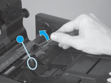
Document feeder white backing (X585 models)
1.Open the document feeder.
Figure 1-13 Remove the document feeder white backing (1 of 3)
2.Carefully remove the white backing.
Figure 1-14 Remove the document feeder white backing (2 of 3)
14 Chapter 1 Removal and replacement |
ENWW |
3.Remove any rubber stoppers that might still be attached to the document feeder.
Figure 1-15 Remove the document feeder white backing (3 of 3)
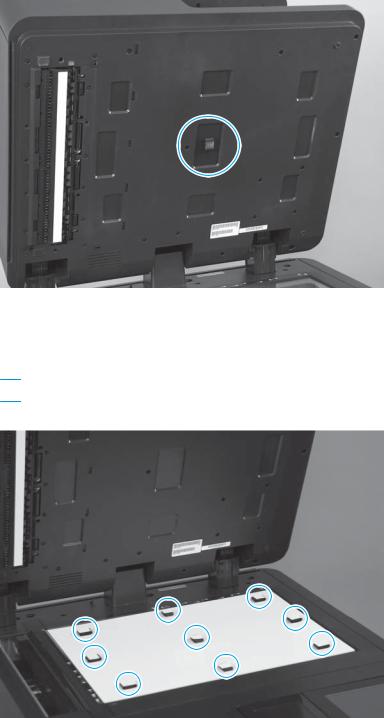
Install a replacement document feeder white backing
1.Position the replacement white backing on the scanner glass. Carefully remove the protective backing from the rubber stoppers.
 CAUTION: Do not touch the exposed adhesive.
Figure 1-16 Install a replacement document feeder white backing (1 of 6)
ENWW |
Removal and replacement procedures 15 |
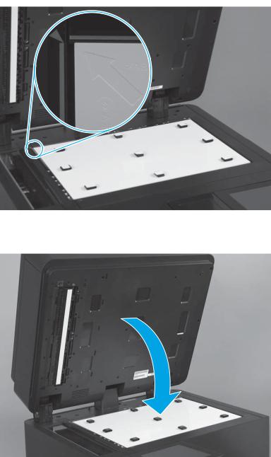
2.Make sure that the arrow on the replacement white backing is positioned in the upper-left corner of the scanner glass.
Figure 1-17 Install a replacement document feeder white backing (2 of 6)
3.Completely close the document feeder.
Figure 1-18 Install a replacement document feeder white backing (3 of 6)
16 Chapter 1 Removal and replacement |
ENWW |
Loading...