


 Loading...
HP LaserJet M1522 MFP Series
Service Manual

HP LaserJet M1522 MFP Series
Service Manual
Copyright and License
© 2008 Copyright Hewlett-Packard
Development Company, L.P.
Reproduction, adaptation, or translation without prior written permission is prohibited, except as allowed under the copyright laws.
The information contained herein is subject to change without notice.
The only warranties for HP products and services are set forth in the express warranty statements accompanying such products and services. Nothing herein should be construed as constituting an additional warranty. HP shall not be liable for technical or editorial errors or omissions contained herein.
Edition 1, 1/2008
Part number: CB534-90945
Trademark Credits
Adobe®, Acrobat®, and PostScript® are trademarks of Adobe Systems Incorporated.
Microsoft®, Windows®, and Windows NT® are U.S. registered trademarks of Microsoft Corporation.
UNIX® is a registered trademark of The Open Group.

Table of contents
1 |
Product information |
|
|
Quick access to product information .................................................................................................... |
2 |
|
Product comparison ............................................................................................................................. |
3 |
|
Product features ................................................................................................................................... |
4 |
|
Product walkaround .............................................................................................................................. |
5 |
|
Front view ............................................................................................................................ |
5 |
|
Back view ............................................................................................................................. |
5 |
|
Interface ports ...................................................................................................................... |
6 |
|
Control-panel ....................................................................................................................... |
6 |
|
Serial number and model number location .......................................................................... |
7 |
|
Software description ............................................................................................................................. |
8 |
|
Supported operating systems .............................................................................................. |
8 |
|
Supported printer drivers ..................................................................................................... |
8 |
|
Software included with the product ...................................................................................... |
8 |
|
Recommended installation for Windows ............................................................. |
8 |
|
Express installation (USB or network) ................................................................. |
9 |
|
Macintosh software ............................................................................................. |
9 |
|
Software for Windows .......................................................................................................................... |
9 |
|
HP ToolboxFX ..................................................................................................................... |
9 |
|
Embedded Web server (EWS) .......................................................................................... |
10 |
|
Software for Macintosh ....................................................................................................................... |
10 |
|
HP Director ........................................................................................................................ |
10 |
|
Macintosh Configure Device (Mac OS X v10.3, v10.4, and later) ..................................... |
10 |
|
PDEs (Mac OS X v10.3, v10.4, and later) ......................................................................... |
11 |
|
Uninstall software ............................................................................................................................... |
11 |
|
Windows ............................................................................................................................ |
11 |
|
Macintosh .......................................................................................................................... |
11 |
|
Media specifications ........................................................................................................................... |
12 |
|
Supported paper and print media sizes ............................................................................. |
12 |
|
Supported paper types and tray capacity .......................................................................... |
13 |
2 |
Installation |
|
|
Site preparations ................................................................................................................................ |
16 |
|
Operating environment ...................................................................................................... |
16 |
|
Minimum system requirements .......................................................................................... |
17 |
|
What was in the box ........................................................................................................................... |
18 |
|
Install input devices ............................................................................................................................ |
19 |
|
ADF input tray .................................................................................................................... |
19 |
|
Priority input tray ................................................................................................................ |
20 |
ENWW |
iii |
Tray 1 ................................................................................................................................. |
21 |
Install supplies .................................................................................................................................... |
22 |
Install the print cartridge .................................................................................................... |
22 |
3 Maintenance |
|
Manage supplies ................................................................................................................................ |
26 |
Life expectancies of supplies ............................................................................................. |
26 |
Check and order supplies .................................................................................................. |
26 |
Store supplies .................................................................................................................... |
26 |
Replace supplies ............................................................................................................... |
27 |
Print cartridge .................................................................................................... |
27 |
HP policy on non-HP supplies ........................................................................................... |
28 |
HP fraud hotline ................................................................................................................. |
29 |
Clean the product ............................................................................................................................... |
30 |
Clean the exterior .............................................................................................................. |
30 |
Clean the flatbed scanner glass ........................................................................................ |
30 |
Clean the scanner-cover backing ...................................................................................... |
31 |
Clean the ADF pickup-roller assembly .............................................................................. |
32 |
Clean the paper path ......................................................................................................... |
34 |
Clean the paper path from HP ToolboxFX ........................................................ |
34 |
Clean the paper path from the product control panel ........................................ |
34 |
Calibrate the scanner ......................................................................................................... |
34 |
Calibrate the scanner from HP ToolboxFX ....................................................... |
35 |
Calibrate the scanner from the product control panel ....................................... |
35 |
Management tools .............................................................................................................................. |
36 |
Information pages .............................................................................................................. |
36 |
HP ToolboxFX ................................................................................................................... |
37 |
View HP ToolboxFX .......................................................................................... |
37 |
Status ................................................................................................................ |
38 |
Event log ........................................................................................... |
38 |
Alerts ................................................................................................................. |
38 |
Set up status alerts ........................................................................... |
38 |
Set up e-mail alerts ........................................................................... |
38 |
Fax .................................................................................................................... |
39 |
Fax tasks .......................................................................................... |
39 |
Fax phone book ................................................................................ |
39 |
Fax send log ..................................................................................... |
41 |
Fax receive log ................................................................................. |
41 |
Block Faxes ...................................................................................... |
41 |
Help ................................................................................................................... |
41 |
System Settings ................................................................................................ |
42 |
Device information ............................................................................ |
42 |
Paper handling ................................................................................. |
43 |
Print quality ....................................................................................... |
43 |
Paper types ...................................................................................... |
43 |
System setup .................................................................................... |
44 |
Service .............................................................................................. |
44 |
Device polling ................................................................................... |
44 |
Print Settings ..................................................................................................... |
44 |
Printing ............................................................................................. |
44 |
iv |
ENWW |
PCL 5e .............................................................................................. |
45 |
PostScript ......................................................................................... |
45 |
Network Settings ............................................................................................... |
45 |
Embedded Web server ...................................................................................................... |
45 |
Features ............................................................................................................ |
45 |
Use HP Web Jetadmin software ........................................................................................ |
46 |
4 Operational theory |
|
Basic operation ................................................................................................................................... |
48 |
Sequence of operation for the base unit ............................................................................ |
48 |
Scanner and ADF functions and operation ........................................................................................ |
50 |
Scanner functions ............................................................................................................. |
50 |
Scanner operation ............................................................................................................. |
51 |
ADF operation .................................................................................................................... |
51 |
ADF paper path and ADF sensors ..................................................................................... |
52 |
ADF jam detection ............................................................................................................. |
53 |
Internal components (base unit) ......................................................................................................... |
54 |
Engine control system ........................................................................................................................ |
55 |
Laser/scanner system ........................................................................................................................ |
57 |
Pickup/feed/delivery system ............................................................................................................... |
58 |
Image-formation system .................................................................................................................... |
59 |
Fax functions and operation (fax models only) ................................................................................... |
63 |
Computer and network security features ........................................................................... |
63 |
PSTN operation ................................................................................................................. |
63 |
Receive faxes when you hear fax tones ............................................................................ |
63 |
Distinctive ring function ...................................................................................................... |
64 |
Fax by using Voice over IP services .................................................................................. |
64 |
The fax subsystem ............................................................................................................. |
65 |
Fax card in the fax subsystem ........................................................................................... |
65 |
Safety isolation .................................................................................................. |
65 |
Safety-protection circuitry .................................................................................. |
65 |
Data path ........................................................................................................... |
66 |
Hook state ......................................................................................................... |
66 |
Downstream device detection ........................................................................... |
66 |
Hook switch control ........................................................................................... |
66 |
Ring detect ........................................................................................................ |
67 |
Line current control ........................................................................................... |
67 |
Billing- (metering-) tone filters ........................................................................... |
67 |
Fax page storage in flash memory .................................................................................... |
67 |
Stored fax pages ............................................................................................... |
67 |
Advantages of flash memory storage ............................................................... |
67 |
5 Removal and replacement |
|
Removal and replacement strategy .................................................................................................... |
70 |
Introduction ........................................................................................................................ |
70 |
Removal and replacement warnings, cautions, notes and tips ......................... |
70 |
Electrostatic discharge ...................................................................................... |
71 |
Required tools ................................................................................................... |
71 |
Before performing service .................................................................................................. |
71 |
After performing service ..................................................................................................... |
72 |
ENWW |
v |
Post-service tests .............................................................................................................. |
73 |
Test 1 (print-quality test) ................................................................................... |
73 |
Test 2 (copy-quality test) ................................................................................... |
73 |
Test 3 (fax-quality test) ...................................................................................... |
73 |
Parts removal order ........................................................................................................... |
74 |
Scanner and ADF components .......................................................................................................... |
75 |
ADF input tray .................................................................................................................... |
75 |
Flatbed lid .......................................................................................................................... |
76 |
Link assemblies and scanner support-frame springs ........................................................ |
79 |
Control-panel bezel ............................................................................................................ |
81 |
Control-panel assembly ..................................................................................................... |
82 |
ADF separation pad ........................................................................................................... |
83 |
ADF input-tray flag ............................................................................................................. |
84 |
ADF pickup roller assembly .............................................................................................. |
85 |
ADF scanner glass ............................................................................................................ |
88 |
Scanner assembly ............................................................................................................. |
90 |
Product base ...................................................................................................................................... |
95 |
Print cartridge .................................................................................................................... |
95 |
Separation pad (product base) .......................................................................................... |
96 |
Pickup roller (product base) ............................................................................................... |
97 |
Scanner cushions ............................................................................................................ |
100 |
Media input tray ............................................................................................................... |
101 |
Transfer roller .................................................................................................................. |
103 |
Side covers ...................................................................................................................... |
104 |
Print-cartridge door .......................................................................................................... |
106 |
Rear cover and fuser cover ............................................................................................. |
107 |
Front cover ....................................................................................................................... |
109 |
Speaker assembly ........................................................................................................... |
111 |
Formatter and fax card .................................................................................................... |
113 |
Power supply ................................................................................................................... |
114 |
Scanner support-frame .................................................................................................... |
118 |
Laser/scanner assembly .................................................................................................. |
121 |
Main motor ....................................................................................................................... |
125 |
Fuser ................................................................................................................................ |
128 |
Paper-pickup assembly ................................................................................................... |
132 |
Drive-gear assembly and drive belt ................................................................................. |
135 |
6 Problem solve |
|
Problem-solving checklist ................................................................................................................. |
138 |
Control-panel messages .................................................................................................................. |
140 |
Alert and warning messages .......................................................................................... |
140 |
Alert and warning message tables .................................................................. |
140 |
Critical error messages .................................................................................................... |
147 |
Critical error message-tables .......................................................................... |
147 |
Clear jams ........................................................................................................................................ |
149 |
Causes of jams ................................................................................................................ |
149 |
Where to look for jams ..................................................................................................... |
150 |
Clear jams from the ADF ................................................................................................. |
151 |
Clear jams from the input-tray areas ............................................................................... |
153 |
Clear jams from the output bin ......................................................................................... |
155 |
vi |
ENWW |
Clear jams from the print-cartridge area .......................................................................... |
156 |
Print problems .................................................................................................................................. |
157 |
Print-quality problems ...................................................................................................... |
157 |
Improve print quality ........................................................................................ |
157 |
Print-quality settings ....................................................................... |
157 |
Identify and correct print defects ..................................................................... |
158 |
Print-quality checklist ...................................................................... |
158 |
General print-quality issues ............................................................ |
158 |
Scan problems ................................................................................................................................. |
163 |
Solve scanned-image problems ...................................................................................... |
163 |
Scan-quality problems ..................................................................................................... |
165 |
Prevent problems ............................................................................................ |
165 |
Solve scan-quality problems ........................................................................... |
165 |
Copy problems ................................................................................................................................. |
166 |
Prevent problems ............................................................................................................. |
166 |
Image problems ............................................................................................................... |
166 |
Media-handling problems ................................................................................................ |
167 |
Performance problems .................................................................................................... |
169 |
Fax problems (fax models only) ....................................................................................................... |
170 |
General fax problem-solve ............................................................................................... |
170 |
Problems receiving faxes ................................................................................................. |
171 |
Problems sending faxes .................................................................................................. |
174 |
Voice-call problems ......................................................................................................... |
175 |
Media-handling problems ................................................................................................ |
176 |
Performance problems .................................................................................................... |
177 |
Functional checks ............................................................................................................................. |
178 |
Engine test page .............................................................................................................. |
178 |
Drum rotation test ............................................................................................................ |
178 |
Half self-test functional check .......................................................................................... |
179 |
Perform a half self-test check .......................................................................... |
179 |
Perform other checks ..................................................................................... |
179 |
Heating element check .................................................................................................... |
180 |
High-voltage contacts check ............................................................................................ |
180 |
Check the print-cartridge contacts ................................................................ |
180 |
Check the high-voltage connector assembly .................................................. |
181 |
Service-mode functions .................................................................................................................... |
182 |
NVRAM initialization ........................................................................................................ |
182 |
Super NVRAM initialization .............................................................................................. |
182 |
Secondary service menu ................................................................................................. |
182 |
Problem-solve tools .......................................................................................................................... |
184 |
Product information pages and reports ............................................................................ |
184 |
Configuration page .......................................................................................... |
184 |
Supplies Status page ...................................................................................... |
184 |
PCL, PCL 6, or PS font list .............................................................................. |
184 |
Demo page ...................................................................................................... |
185 |
Usage page ..................................................................................................................... |
185 |
Menu map ........................................................................................................................ |
185 |
Network report ................................................................................................................. |
185 |
Fax reports ....................................................................................................................... |
186 |
Fax activity log ................................................................................................ |
186 |
ENWW |
vii |
Fax confirmation report ................................................................................... |
186 |
Last call report ................................................................................................. |
186 |
Phone book report ........................................................................................... |
186 |
Billing-code report ........................................................................................... |
188 |
HP ToolboxFX ................................................................................................................. |
188 |
View HP ToolboxFX ........................................................................................ |
188 |
Troubleshooting tab ........................................................................................ |
188 |
Service menu ................................................................................................................... |
189 |
Restore the factory-set defaults ...................................................................... |
189 |
Clean the paper path ....................................................................................... |
190 |
T.30 protocol trace .......................................................................................... |
191 |
Archive print .................................................................................................... |
191 |
Problem-solve diagrams ................................................................................................................... |
192 |
Repetitive image defects ................................................................................................. |
192 |
Interface ports .................................................................................................................. |
193 |
ECU connectors ............................................................................................................... |
194 |
Formatter PCA ................................................................................................................. |
195 |
Fax card ........................................................................................................................... |
196 |
Solenoid and motor .......................................................................................................... |
197 |
Rollers .............................................................................................................................. |
198 |
Sensors ............................................................................................................................ |
199 |
Major components ........................................................................................................... |
200 |
PCAs (base unit) .............................................................................................................. |
201 |
Scanner and ADF ............................................................................................................ |
202 |
Circuit diagram ................................................................................................................. |
203 |
Firmware updates ............................................................................................................................. |
204 |
Firmware update by using a flash executable file ............................................................ |
204 |
7 Parts |
|
Ordering information ......................................................................................................................... |
206 |
Supplies and hinge tool .................................................................................................................... |
206 |
Cable and interface accessories ...................................................................................................... |
206 |
Whole unit replacement .................................................................................................................... |
207 |
Control-panel bezels ........................................................................................................................ |
211 |
Supplementry documentation and support ....................................................................................... |
214 |
Parts lists and diagrams ................................................................................................................... |
216 |
Types of screws ............................................................................................................... |
217 |
ADF and scanner assemblies .......................................................................................................... |
218 |
ADF internal components ................................................................................................................. |
220 |
Assemblies ....................................................................................................................................... |
222 |
External covers and panels .............................................................................................................. |
224 |
Internal components (1 of 3) ............................................................................................................ |
226 |
Internal components (2 of 3) ............................................................................................................ |
228 |
Internal components (3 of 3) ............................................................................................................ |
230 |
Alphabetical parts list ....................................................................................................................... |
232 |
Numerical parts list ........................................................................................................................... |
235 |
Appendix A Service and support |
|
Hewlett-Packard limited warranty statement .................................................................................... |
239 |
Customer self repair warranty service .............................................................................................. |
240 |
viii |
ENWW |
Print cartridge limited warranty statement ........................................................................................ |
241 |
Customer support ............................................................................................................................. |
242 |
HP maintenance agreements ........................................................................................................... |
242 |
Repacking the device ...................................................................................................... |
242 |
Extended warranty ........................................................................................................... |
242 |
Appendix B Specifications |
|
Physical specifications ..................................................................................................................... |
244 |
Electrical specifications .................................................................................................................... |
244 |
Power consumption .......................................................................................................................... |
244 |
Environmental specifications ............................................................................................................ |
245 |
Acoustic emissions ........................................................................................................................... |
245 |
Appendix C Regulatory information |
|
FCC compliance ............................................................................................................................... |
248 |
Environmental product stewardship program ................................................................................... |
249 |
Protecting the environment .............................................................................................. |
249 |
Ozone production ............................................................................................................ |
249 |
Power consumption ......................................................................................................... |
249 |
Toner consumption .......................................................................................................... |
249 |
Paper use ........................................................................................................................ |
249 |
Plastics ............................................................................................................................ |
249 |
HP LaserJet print supplies ............................................................................................... |
249 |
Return and recycling instructions ..................................................................................... |
250 |
United States and Puerto Rico ........................................................................ |
250 |
Multiple returns (two to eight cartridges) ........................................ |
250 |
Single returns ................................................................................. |
250 |
Shipping .......................................................................................... |
250 |
Non-US returns ............................................................................................... |
250 |
Paper ............................................................................................................................... |
250 |
Material restrictions .......................................................................................................... |
250 |
Disposal of waste equipment by users in private households in the European Union .... |
251 |
Material Safety Data Sheet (MSDS) ................................................................................ |
251 |
For more information ....................................................................................................... |
252 |
Telephone Consumer Protection Act (United States) ...................................................................... |
253 |
IC CS-03 requirements ..................................................................................................................... |
253 |
EU statement for telecom operation ................................................................................................. |
254 |
New Zealand telecom statements .................................................................................................... |
254 |
Declaration of conformity .................................................................................................................. |
255 |
Declaration of conformity .................................................................................................................. |
256 |
Safety statements ............................................................................................................................. |
257 |
Laser safety ..................................................................................................................... |
257 |
Canadian DOC regulations .............................................................................................. |
257 |
EMI statement (Korea) ..................................................................................................... |
257 |
Laser statement for Finland ............................................................................................. |
258 |
Substances table (China) ................................................................................................ |
259 |
Index ................................................................................................................................................................. |
261 |
ENWW |
ix |
x |
ENWW |

List of tables
Table 1-1 |
Product guides ................................................................................................................................... |
2 |
Table 1-2 Supported paper and print media sizes ........................................................................................... |
12 |
|
Table 1-3 Supported envelopes and postcards ............................................................................................... |
13 |
|
Table 4-1 Sequence of operation ..................................................................................................................... |
48 |
|
Table 4-2 |
Power-on sequence ......................................................................................................................... |
49 |
Table 6-1 Alert and warning messages ......................................................................................................... |
140 |
|
Table 6-2 Critical error messages .................................................................................................................. |
147 |
|
Table 6-3 Repetitive image defects ................................................................................................................ |
192 |
|
Table 6-4 |
ECU connectors ............................................................................................................................. |
194 |
Table 6-5 |
Formatter connectors ..................................................................................................................... |
195 |
Table 6-6 |
Fax card ......................................................................................................................................... |
196 |
Table 6-7 Solenoid and motor ........................................................................................................................ |
197 |
|
Table 6-8 |
Rollers ............................................................................................................................................ |
198 |
Table 6-9 |
Sensors .......................................................................................................................................... |
199 |
Table 6-10 |
Major components ........................................................................................................................ |
200 |
Table 6-11 PCAs (base unit) .......................................................................................................................... |
201 |
|
Table 6-12 Scanner and ADF ......................................................................................................................... |
202 |
|
Table 7-1 Whole unit replacement, product bundle CC372A ......................................................................... |
207 |
|
Table 7-2 Whole unit replacement, product bundle CB534A ......................................................................... |
209 |
|
Table 7-3 Control-panel bezels (HP LaserJet M1522n) ................................................................................. |
211 |
|
Table 7-4 Control-panel bezels (HP LaserJet M1522nf) ................................................................................ |
212 |
|
Table 7-5 |
Documentation ............................................................................................................................... |
214 |
Table 7-6 Scanner and ADF assemblies ........................................................................................................ |
219 |
|
Table 7-7 ADF internal components ............................................................................................................... |
221 |
|
Table 7-8 |
Assemblies ..................................................................................................................................... |
223 |
Table 7-9 External covers and panels ............................................................................................................ |
225 |
|
Table 7-10 Internal components (1 of 3) ........................................................................................................ |
227 |
|
Table 7-11 Internal components (2 of 3) ........................................................................................................ |
229 |
|
Table 7-12 Internal components (3 of 3) ........................................................................................................ |
231 |
|
Table 7-13 Alphabetical parts list ................................................................................................................... |
232 |
|
Table 7-14 Numerical parts list ....................................................................................................................... |
235 |
|
Table B-1 |
Physical specifications ................................................................................................................... |
244 |
Table B-2 |
Electrical specifications .................................................................................................................. |
244 |
Table B-3 Power consumption (average, in watts) ....................................................................................... |
244 |
|
Table B-4 |
Environmental specifications ........................................................................................................ |
245 |
Table B-5 |
Acoustic emissions ....................................................................................................................... |
245 |
ENWW |
xi |
xii |
ENWW |

List of figures
Figure 2-1 |
Operating environment ................................................................................................................... |
16 |
Figure 4-1 System block diagram ..................................................................................................................... |
48 |
|
Figure 4-2 |
Optical system ................................................................................................................................ |
50 |
Figure 4-3 ADF paper path ............................................................................................................................... |
52 |
|
Figure 4-4 Cross-section of printer ................................................................................................................... |
54 |
|
Figure 4-5 Engine control system ..................................................................................................................... |
55 |
|
Figure 4-6 Engine-control-system circuit diagram ............................................................................................ |
56 |
|
Figure 4-7 |
Laser/scanner system ..................................................................................................................... |
57 |
Figure 4-8 |
Pickup/feed/delivery system ........................................................................................................... |
58 |
Figure 4-9 |
Image-formation system ................................................................................................................. |
59 |
Figure 4-10 |
Primary charging ........................................................................................................................... |
59 |
Figure 4-11 |
Developing .................................................................................................................................... |
60 |
Figure 4-12 |
Transfer ......................................................................................................................................... |
61 |
Figure 4-13 |
Separation ..................................................................................................................................... |
61 |
Figure 4-14 |
Fusing ........................................................................................................................................... |
61 |
Figure 4-15 |
Drum cleaning ............................................................................................................................... |
62 |
Figure 5-1 Phillips and pozidrive screwdriver comparison ............................................................................... |
71 |
|
Figure 5-2 Parts removal order for the scanner and ADF ................................................................................ |
74 |
|
Figure 5-3 Parts removal order for the product (product base) ........................................................................ |
74 |
|
Figure 5-4 Remove the ADF input tray ............................................................................................................. |
75 |
|
Figure 5-5 Remove the flatbed lid (1 of 5) ........................................................................................................ |
76 |
|
Figure 5-6 ADF cover correctly installed .......................................................................................................... |
76 |
|
Figure 5-7 Remove the flatbed lid (2 of 5) ........................................................................................................ |
77 |
|
Figure 5-8 Remove the flatbed lid (3 of 5) ........................................................................................................ |
77 |
|
Figure 5-9 Remove the flatbed lid (4 of 5) ........................................................................................................ |
78 |
|
Figure 5-10 Remove the flatbed lid (5 of 5) ...................................................................................................... |
78 |
|
Figure 5-11 Remove the link assemblies and scanner support-frame springs (1 of 4) .................................... |
79 |
|
Figure 5-12 Remove the link assemblies and scanner support-frame springs (2 of 4) .................................... |
79 |
|
Figure 5-13 Remove the link assemblies and scanner support-frame springs (3 of 4) .................................... |
80 |
|
Figure 5-14 Remove the link assemblies and scanner support-frame springs (4 of 4) .................................... |
80 |
|
Figure 5-15 Remove the control-panel bezel ................................................................................................... |
81 |
|
Figure 5-16 Remove the control-panel assembly (1 of 2) ................................................................................ |
82 |
|
Figure 5-17 Remove the control-panel assembly (2 of 2) ................................................................................ |
82 |
|
Figure 5-18 Remove the ADF separation pad ................................................................................................. |
83 |
|
Figure 5-19 Remove the ADF input-tray flag .................................................................................................... |
84 |
|
Figure 5-20 Replacing the ADF pickup roller assembly (1 of 6) ....................................................................... |
85 |
|
Figure 5-21 Replacing the ADF pickup roller assembly (2 of 6) ....................................................................... |
85 |
|
Figure 5-22 Replacing the ADF pickup roller assembly (3 of 6) ....................................................................... |
86 |
|
Figure 5-23 Replacing the ADF pickup roller assembly (4 of 6) ....................................................................... |
86 |
|
ENWW |
xiii |
Figure 5-24 Replacing the ADF pickup roller assembly (5 of 6) |
....................................................................... 87 |
Figure 5-25 Replacing the ADF pickup roller (6 of 6) ....................................................................................... |
87 |
Figure 5-26 Remove the ADF scanner glass (1 of 3) ....................................................................................... |
88 |
Figure 5-27 Remove the ADF scanner glass (2 of 3) ....................................................................................... |
88 |
Figure 5-28 Remove the ADF scanner glass (3 of 3) ....................................................................................... |
89 |
Figure 5-29 Remove the scanner assembly (1 of 10) ...................................................................................... |
90 |
Figure 5-30 Remove the scanner assembly (2 of 10) ...................................................................................... |
90 |
Figure 5-31 Remove the scanner assembly (3 of 10) ...................................................................................... |
91 |
Figure 5-32 Remove the scanner assembly (4 of 10) ...................................................................................... |
91 |
Figure 5-33 Remove the scanner assembly (5 of 10) ...................................................................................... |
92 |
Figure 5-34 Remove the scanner assembly (6 of 10) ...................................................................................... |
92 |
Figure 5-35 Remove the scanner assembly (7 of 10) ...................................................................................... |
93 |
Figure 5-36 Remove the scanner assembly (8 of 10) ...................................................................................... |
93 |
Figure 5-37 Remove the scanner assembly (9 of 10) ...................................................................................... |
94 |
Figure 5-38 Remove the scanner assembly (10 of 10) .................................................................................... |
94 |
Figure 5-39 Remove the print cartridge (1 of 2) ............................................................................................... |
95 |
Figure 5-40 Remove the print cartridge (2 of 2) ............................................................................................... |
95 |
Figure 5-41 Remove the product separation pad (1 of 2) ................................................................................ |
96 |
Figure 5-42 Remove the product separation pad (2 of 2) ................................................................................ |
96 |
Figure 5-43 Remove the product pickup roller (1 of 5) ..................................................................................... |
97 |
Figure 5-44 Remove the product pickup roller (2 of 5) ..................................................................................... |
97 |
Figure 5-45 Remove the product pickup roller (3 of 5) ..................................................................................... |
98 |
Figure 5-46 Remove the product pickup roller (4 of 5) ..................................................................................... |
98 |
Figure 5-47 Remove the product pickup roller (5 of 5) ..................................................................................... |
99 |
Figure 5-48 Installing the scanner cushions ................................................................................................... |
100 |
Figure 5-49 Remove the media input tray (1 of 3) ......................................................................................... |
101 |
Figure 5-50 Remove the media input tray (2 of 3) ......................................................................................... |
101 |
Figure 5-51 Remove the media input tray (3 of 3) ......................................................................................... |
102 |
Figure 5-52 Remove the transfer roller .......................................................................................................... |
103 |
Figure 5-53 Remove the side covers (1 of 4) ................................................................................................. |
104 |
Figure 5-54 Remove the side covers (2 of 4) ................................................................................................. |
104 |
Figure 5-55 Remove the side covers (3 of 4) ................................................................................................. |
105 |
Figure 5-56 Remove the side covers (4 of 4) ................................................................................................. |
105 |
Figure 5-57 Remove the print-cartridge door (1 of 2) ..................................................................................... |
106 |
Figure 5-58 Remove the print-cartridge door (2 of 2) ..................................................................................... |
106 |
Figure 5-59 Remove the rear cover and fuser cover (1 of 3) ......................................................................... |
107 |
Figure 5-60 Remove the rear cover and fuser cover (2 of 3) ......................................................................... |
107 |
Figure 5-61 Remove the rear cover and fuser cover (3 of 3) ......................................................................... |
108 |
Figure 5-62 Remove the front cover (1 of 4) .................................................................................................. |
109 |
Figure 5-63 Remove the front cover (2 of 4) .................................................................................................. |
109 |
Figure 5-64 Remove the front cover (3 of 4) .................................................................................................. |
110 |
Figure 5-65 Remove the front cover (4 of 4) .................................................................................................. |
110 |
Figure 5-66 Remove the speaker assembly (1 of 2) ...................................................................................... |
111 |
Figure 5-67 Remove the speaker assembly (2 of 2) ...................................................................................... |
111 |
Figure 5-68 Remove the formatter ................................................................................................................. |
113 |
Figure 5-69 Remove the power supply (1 of 7) .............................................................................................. |
114 |
Figure 5-70 Remove the power supply (2 of 7) .............................................................................................. |
115 |
Figure 5-71 Remove the power supply (3 of 7) .............................................................................................. |
115 |
Figure 5-72 Remove the power supply (4 of 7) .............................................................................................. |
116 |
Figure 5-73 Remove the power supply (5 of 7) .............................................................................................. |
116 |
xiv |
ENWW |
Figure 5-74 Remove the power supply (7 of 7) .............................................................................................. |
117 |
|
Figure 5-75 Remove the power supply (7 of 7) .............................................................................................. |
117 |
|
Figure 5-76 Remove the scanner support-frame (1 of 5) ............................................................................... |
118 |
|
Figure 5-77 Remove the scanner support-frame (2 of 5) ............................................................................... |
119 |
|
Figure 5-78 Remove the scanner support-frame (3 of 5) ............................................................................... |
119 |
|
Figure 5-79 Remove the scanner support-frame (4 of 5) ............................................................................... |
120 |
|
Figure 5-80 Remove the scanner support-frame (5 of 5) ............................................................................... |
120 |
|
Figure 5-81 Remove the laser/scanner (1 of 7) ............................................................................................. |
121 |
|
Figure 5-82 Remove the laser/scanner (2 of 7) ............................................................................................. |
122 |
|
Figure 5-83 Remove the laser/scanner (3 of 7) ............................................................................................. |
122 |
|
Figure 5-84 Remove the laser/scanner (4 of 7) ............................................................................................. |
123 |
|
Figure 5-85 Remove the laser/scanner assembly (5 of 7) ............................................................................. |
123 |
|
Figure 5-86 Remove the laser/scanner assembly (6 of 7) ............................................................................. |
124 |
|
Figure 5-87 Remove the laser/scanner assembly (7 of 7)Remove the laser/scanner assembly (7 of 7) ....... |
124 |
|
Figure 5-88 Remove the main motor (1 of 4) ................................................................................................. |
125 |
|
Figure 5-89 Remove the main motor (2 of 4) ................................................................................................. |
126 |
|
Figure 5-90 Remove the main motor (3 of 4) ................................................................................................. |
126 |
|
Figure 5-91 Remove the main motor (4 of 4) ................................................................................................. |
127 |
|
Figure 5-92 Remove the fuser (1 of 6) ........................................................................................................... |
128 |
|
Figure 5-93 Remove the fuser (2 of 6) ........................................................................................................... |
129 |
|
Figure 5-94 Remove the fuser (3 of 6) ........................................................................................................... |
129 |
|
Figure 5-95 Remove the fuser (4 of 6) ........................................................................................................... |
130 |
|
Figure 5-96 Remove the fuser assembly (5 of 6) ........................................................................................... |
130 |
|
Figure 5-97 Remove the fuser assembly (6 of 6) ........................................................................................... |
131 |
|
Figure 5-98 Remove the paper-pickup assembly (1 of 4) .............................................................................. |
132 |
|
Figure 5-99 Remove the paper-pickup assembly (2 of 4) .............................................................................. |
133 |
|
Figure 5-100 Remove the paper-pickup assembly (3 of 4) ............................................................................ |
133 |
|
Figure 5-101 Remove the paper-pickup assembly (4 of 4) ............................................................................ |
134 |
|
Figure 5-102 Remove the Drive-gear assembly and drive belt (1 of 4). ........................................................ |
135 |
|
Figure 5-103 Remove the Drive-gear assembly and drive belt (2 of 4). ........................................................ |
135 |
|
Figure 5-104 Remove the Drive-gear assembly and drive belt (3 of 4). ........................................................ |
136 |
|
Figure 5-105 Remove the Drive-gear assembly and drive belt (4 of 4). ........................................................ |
136 |
|
Figure 6-1 Print-cartridge high-voltage connection points (right side) ............................................................ |
180 |
|
Figure 6-2 Print-cartridge high-voltage connection points (left side) .............................................................. |
181 |
|
Figure 6-3 |
ECU connectors ............................................................................................................................ |
194 |
Figure 6-4 |
Formatter connectors .................................................................................................................... |
195 |
Figure 6-5 Fax card connectors ..................................................................................................................... |
196 |
|
Figure 6-6 Solenoid and motor ....................................................................................................................... |
197 |
|
Figure 6-7 |
Rollers ........................................................................................................................................... |
198 |
Figure 6-8 |
Sensors ......................................................................................................................................... |
199 |
Figure 6-9 |
Major components ........................................................................................................................ |
200 |
Figure 6-10 PCAs (base unit) ......................................................................................................................... |
201 |
|
Figure 6-11 Scanner and ADF ....................................................................................................................... |
202 |
|
Figure 6-12 |
Circuit diagram ........................................................................................................................... |
203 |
Figure 7-1 Scanner and ADF assemblies ...................................................................................................... |
218 |
|
Figure 7-2 ADF internal components ............................................................................................................. |
220 |
|
Figure 7-3 |
Assemblies .................................................................................................................................... |
222 |
Figure 7-4 External covers and panels .......................................................................................................... |
224 |
|
Figure 7-5 Internal components (1 of 3) ......................................................................................................... |
226 |
|
Figure 7-6 Internal components (2 of 3) ......................................................................................................... |
228 |
|
ENWW |
xv |
Figure 7-7 Internal components (3 of 3) ......................................................................................................... |
230 |
xvi |
ENWW |

1 Product information
●Quick access to product information
●Product comparison
●Product features
●Product walkaround
●Software description
●Software for Windows
●Software for Macintosh
●Uninstall software
●Media specifications
ENWW |
1 |

Quick access to product information
Use the following Web site to find information about the product.
●www.hp.com/support/ljm1522
Table 1-1 Product guides
Guide |
Description |
|
|
HP LaserJet M1522 MFP Getting |
Provides step-by-step instructions for installing and setting up the product. |
Started Guide |
|
|
|
HP LaserJet M1522 MFP Series |
Provides detailed information for using the product and problem-solving. Available on the |
User Guide |
product CD or in Program Group if the software is installed on a computer. |
|
|
HP ToolboxFX |
To check the product status and settings, and to view problem-solving information and online |
|
documentation, use the HP ToolboxFX. You must have performed a complete software |
|
installation in order to use the HP ToolboxFX. See the user guide for more information about |
|
software installation. |
|
|
Online Help |
Provides information about options that are available in the printer drivers. To view a Help |
|
file, open the online Help through the printer driver. |
|
|
2 Chapter 1 Product information |
ENWW |
Product comparison
The product is available in the following configurations.
HP LaserJet M1522n MFP |
HP LaserJet M1522nf MFP |
●Prints letter-size pages at speeds up to 24 pages per minute (ppm) and A4-size pages at speeds up to 23 ppm.
●PCL 5 and PCL 6 printer drivers and HP postscript level 3 emulation.
●Priority input tray holds up to 10 sheets of print media.
●Tray 1 holds up to 250 sheets of print media or 10 envelopes.
●Hi-Speed USB 2.0 port and 10/100 Base-T network port.
●64-MB random-access memory (RAM).
●Flatbed scanner and 50-page automatic document feeder (ADF).
HP LaserJet M1522n MFP, plus:
●V.34 fax modem and 4-megabyte (MB) flash fax-storage memory.
●Two RJ-11 fax phone line ports
ENWW |
Product comparison 3 |

Product features
Performance |
● |
Prints up to 24 ppm (letter) or 23 ppm (A4). |
|
|
|
|
|
Print quality |
● |
600 x 2 dots per inch (dpi) with Resolution Enhancement Technology (RET). |
|
|
● Adjustable settings to optimize print quality. |
||
|
● The HP UltraPrecise print cartridge has a finer toner formulation that provides sharper text |
||
|
|
and graphics. |
|
|
|
|
|
Fax (fax models only) |
● |
Full-functionality fax capabilities with a V.34 fax; includes a phone book, fax/tel, and |
|
|
|
delayed-fax features. |
|
|
|
|
|
Copy |
● |
Includes ADF that allows faster, more efficient copy jobs with multiple-page documents. |
|
|
|
|
|
Scan |
● |
The product provides 1,200 pixels per inch (ppi), 24-bit full-color scanning from letter/A4- |
|
|
|
size scanner glass. |
|
|
● The product provides 300 ppi, 24-bit full-color scanning from the automatic document |
||
|
|
feeder (ADF). |
|
|
● Includes an ADF that allows faster, more efficient scan jobs with multiple-page documents. |
||
|
|
|
|
Networking |
● |
TCP/IP |
|
|
|
◦ |
IPv4 |
|
|
◦ |
IPv6 |
|
|
|
|
Printer driver features |
● |
Fast printing performance, built-in Intellifont and TrueType scaling technologies, and |
|
|
|
advanced imaging capabilities are benefits of the PCL 6 printer language. |
|
|
|
|
|
Interface connections |
● |
Hi-Speed USB 2.0 port. |
|
|
● 10/100 Base-T ethernet network port (RJ-45). |
||
|
● RJ-11 fax/phone cable ports (fax models only). |
||
|
|
|
|
Economical printing |
● |
N-up printing (printing more than one page on a sheet). |
|
|
● |
EconoMode setting. |
|
|
|
|
|
Supplies |
● |
A supplies status page that displays the amount of life remaining in the print cartridge. |
|
|
● The product ships with a 1,000-page (average yield) starter cartridge. The average yield |
||
|
|
for replacement cartridges is 2,000 pages. |
|
|
● Authentication for HP print cartridges. |
||
|
● Enabled supplies-ordering capability. |
||
|
|
|
|
Accessibility |
● |
Online user guide that is compatible with text screen-readers. |
|
|
● Print cartridges can be installed and removed by using one hand. |
||
|
● All doors and covers can be opened by using one hand. |
||
|
|
|
|
4 Chapter 1 Product information |
ENWW |
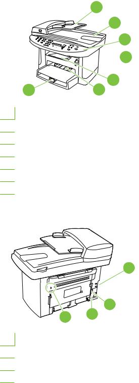
Product walkaround
Front view
1
2
3
 4
4
 5 7 6
5 7 6
1Automatic document feeder (ADF) input tray
2Automatic document feeder (ADF) output bin
3Control panel
4Print-cartridge door latch
5Output bin
6Priority input tray
7Tray 1
Back view
8
9
11 10
8Interface ports
9Power switch
10Power connector
11Kensington lock
ENWW |
Product walkaround 5 |
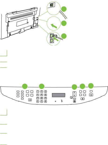
Interface ports
All models have a 10/100 Base-T (RJ-45) network port and a Hi-Speed USB 2.0 port. Fax models have fax ports as well.

 1
1

 2
2
3
1Hi-Speed USB 2.0 port
2Network port
3Fax ports (fax models only)
Control-panel
1 |
2 |
3 |
4 |
5 |
1Fax controls (fax models only). Use the fax controls to change commonly used fax settings.
2Alphanumeric buttons. Use the alphanumeric buttons to type data into the product control-panel display and dial telephone numbers for faxing.
3Setup and cancel controls. Use these controls to select menu options, determine the product status, and cancel the current job.
4 |
Copy controls. Use these controls to change commonly used copy settings and to start copying. |
|
|
5 |
Scan controls. Use these controls to scan to e-mail or to a folder. |
6 Chapter 1 Product information |
ENWW |
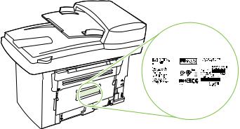
Serial number and model number location
The serial number and product model number label is on the back of the product.
|
|
|
|
|
|
|
|
|
|
|
|
|
|
|
|
|
|
|
|
|
|
|
|
|
|
|
|
|
|
|
|
|
|
|
|
|
|
|
|
|
|
|
|
|
|
|
|
|
|
|
|
ENWW |
|
|
|
|
|
|
|
Product walkaround 7 |
||||

Software description
Supported operating systems
The product supports the following operating systems:
Full software installation |
Print and scan driver |
Printer driver only |
|||
● |
Windows XP (32-bit and 64-bit) |
● |
Windows 2000 |
● |
Linux (Web only) |
● |
Windows Vista (32-bit and 64-bit) |
● |
Windows 2003 Server (32-bit) |
● |
UNIX model scripts (Web only) |
●Mac OS X v10.3, v10.4, and later
 NOTE: For Mac OS X v10.4 and later, PPC and Intel Core Processor Macs are supported.
Supported printer drivers
Operating system |
PCL 5 |
PCL 6 |
HP postscript level 3 |
|
|
|
emulation |
|
|
|
|
Windows |
1 |
|
1 |
|
|
||
|
|
|
|
Mac OS X v10.3, v10.4, and later |
|
|
|
Linux2
1Driver can be installed by using the Microsoft Add Printer wizard, too.
2For Linux, download the HP postscript level 3 emulation driver from www.hp.com/go/linuxprinting.
The printer drivers include online Help that has instructions for common printing tasks and also describes the buttons, checkboxes, and drop-down lists that are in the printer driver.
Software included with the product
There are several options for completing a recommended install. Easy Install will complete the installation with default settings. Advanced Install allows you to select custom settings and choose the components that are installed.
Recommended installation for Windows
●HP drivers
◦PCL 6 printer driver
◦Scan driver
●HP MFP software
◦HP ToolboxFX
◦HP LaserJet Scan program
◦HP Send Fax program and driver
8 Chapter 1 Product information |
ENWW |

◦HP Fax Setup Wizard
◦Uninstall program
●HP Update program
●HP Customer Participation Program
●Shop for HP Supplies program
●Other programs
◦Readiris OCR (not installed with other software; separate installation is required)
Express installation (USB or network)
The following software is included with an Express installation:
●PCL 6 printer driver
●Scan driver
 NOTE: Express installation supports faxing by using the control panel.
NOTE: PCL 5 and HP postscript level 3 emulation drivers can be installed using the Microsoft Add Printer wizard.
Macintosh software
●HP Product Setup Assistant
●HP Device Configuration
●HP Uninstaller
●HP LaserJet software
◦HP Scan
◦HP Director
◦Fax program
◦Scan to e-mail program
◦HP Photosmart
Software for Windows
When you install the software for Windows, you can directly connect the product to a computer by using a USB cable, or you can connect the product to a network by using the internal print server. See the getting started guide for installation instructions, and see the Readme file for the latest software information.
HP ToolboxFX
Perform a typical installation in order to use HP ToolboxFX.
ENWW |
Software for Windows 9 |

HP ToolboxFX provides links to product status information and help information, such as the user guide, and tools for product problem-solving.
Embedded Web server (EWS)
The EWS is a Web-based interface that provides simple access to product status and configurations, including network configurations and Smart Printing Supplies (SPS) functionality.
You can gain access to the EWS through the network connection to the product. Type the product IP address in a Web browser to open the product EWS home page in the browser. From the home page, you can use the tabs and left navigation menu to check the status of the product, configure the product, or check the status of the supplies.
The following are supported browsers:
●Internet Explorer 5.0 or later
●Netscape Navigator 4.75 or later
●Opera 6.05 or later
●Safari 1.2 or later
Software for Macintosh
For Mac OS X v10.3, v10.4, and later, use Print Center to print.
 NOTE: For Macintosh computers, HP ToolboxFX is not supported.
HP Director
HP Director is a software program for working with documents. When the document is loaded into the ADF and the computer is connected directly to the product, HP Director appears on the computer screen to initiate faxing, scanning, or changing settings on the product through Macintosh Configure Device.
Also included is the HP product Setup Assistant, which sets up the fax and print queues.
Macintosh Configure Device (Mac OS X v10.3, v10.4, and later)
Macintosh Configure Device is a Web-based program that provides access to information about the product (or example, information about supplies status and product settings). Use Macintosh Configure Device to monitor and manage the product from the computer.
 NOTE: You must perform a complete software installation to use Macintosh Configure Device.
●Check the product status and print information pages.
●Check and change product settings.
●Check default print settings.
●Check and change fax settings, including IP configuration, Advanced, mDNS, SNMP, network configuration, and fax reports.
You can view Macintosh Configure Device when the product is directly connected to a computer or when it is connected to the network.
10 Chapter 1 Product information |
ENWW |

 NOTE: You do not have to have Internet access to open and use Macintosh Configure Device.
View Macintosh Configure Device when the product is connected to the computer
1.Open HP Director by clicking the HP Director icon in the dock.
2.In HP Director, click Settings.
3.Select Configure Device to open the Macintosh Configure Device home page in a browser.
View Macintosh Configure Device when the product is connected to the network
1.Open one of the following browsers:
●Internet Explorer 5.0 or later
●Netscape Navigator 4.75 or later
●Opera 6.05 or later
●Safari 1.2 or later
2.Type the IP address of the product into the Web browser to open the Macintosh Configure Device home page.
PDEs (Mac OS X v10.3, v10.4, and later)
PDEs are code plug-ins that provide access to product features, such as information about the number of copies, two-sided printing, and quality settings. An installation program for the PDEs and other software is provided on the product CD for Macintosh.
Uninstall software
Windows
Use the Add or Remove Programs method in Windows to remove the product software. This method does not require you to have the software CD.
1.Click Start, point to Settings, and then click Control Panel.
 NOTE: In Windows XP, click Start, and then click Control panel.
2.Double-click Add or Remove Programs.
3.Scroll through the list of software programs and click HP LaserJet M2727.
4.Click Remove.
Macintosh
To remove the software, drag the PPD files to the trash can.
ENWW |
Uninstall software 11 |

Media specifications
Supported paper and print media sizes
This product supports a number of paper sizes, and it adapts to various media.
 NOTE: To obtain best print results, select the appropriate paper size and type in the print driver before printing.
Table 1-2 Supported paper and print media sizes
Size |
Dimensions |
Priority input tray |
Tray 1 |
|
|
|
|
Letter |
216 x 279 mm (8.5 x 11 inches) |
|
|
|
|
|
|
Legal |
216 x 356 mm (8.5 x 14 inches) |
|
|
|
|
|
|
A4 |
210 x 297 mm (8.27 x 11.69 inches) |
|
|
|
|
|
|
Executive |
184 x 267 mm (7.24 x 10.51 inches) |
|
|
|
|
|
|
A3 |
297 x 420 mm (11.69 x 16.54 inches) |
|
|
|
|
|
|
A5 |
148 x 210 mm (5.83 x 8.27 inches) |
|
|
|
|
|
|
A61 |
105 x 148 mm (4.13 x 5.83 inches) |
|
|
|
|
|
|
11 x 17 |
279 x 432 mm (11 x 17 inches) |
|
|
|
|
|
|
B4 (JIS) |
257 x 364 mm (10.12 x 14.33 inches) |
|
|
|
|
|
|
B5 (JIS) |
182 x 257 mm (7.17 x 10.12 inches) |
|
|
|
|
|
|
8k |
270 x 390 mm (10.63 x 15.35 inches) |
|
|
|
|
|
|
16k |
197 x 273 mm (7.75 x 10.75 inches) |
|
|
|
|
|
|
16k |
195 x 270 mm (7.7 x 10.6 inches) |
|
|
|
|
|
|
16k |
184 x 260 mm (7.25 x 10.25 inches) |
|
|
|
|
|
|
8.5 x 13 |
216 x 330 mm (8.5 x 13 inches) |
|
|
|
|
|
|
4 x 61 |
107 x 152 mm (4 x 6 inches) |
|
|
|
|
|
|
5 x 81 |
127 x 203 mm (5 x 8 inches) |
|
|
|
|
|
|
10 x 15 cm1 |
100 x 150 mm (3.9 x 5.9 inches) |
|
|
|
|
|
|
Custom |
Minimum—76 x 127 mm (3 x 5 inches); Maximum— |
|
|
|
216 x 356 mm (8.5 x 14 inches) |
|
|
1 These sizes are supported as custom sizes.
12 Chapter 1 Product information |
ENWW |
Loading...