


 Loading...
HP LaserJet M1120 MFP Series
Service Manual

HP LaserJet M1120 MFP Series
Service Manual
Copyright and License
© 2008 Copyright Hewlett-Packard
Development Company, L.P.
Reproduction, adaptation, or translation without prior written permission is prohibited, except as allowed under the copyright laws.
The information contained herein is subject to change without notice.
The only warranties for HP products and services are set forth in the express warranty statements accompanying such products and services. Nothing herein should be construed as constituting an additional warranty. HP shall not be liable for technical or editorial errors or omissions contained herein.
Edition 1, 1/2008
Part number: CB537-90945
Trademark Credits
Adobe®, Acrobat®, and PostScript® are trademarks of Adobe Systems Incorporated.
Microsoft®, Windows®, and Windows NT® are U.S. registered trademarks of Microsoft Corporation.
UNIX® is a registered trademark of The Open Group.

Table of contents
1 |
Product information |
|
|
Quick access to product information .................................................................................................... |
2 |
|
Product comparison ............................................................................................................................. |
3 |
|
Product features ................................................................................................................................... |
4 |
|
Product walkaround .............................................................................................................................. |
5 |
|
Front view ............................................................................................................................ |
5 |
|
Back view ............................................................................................................................. |
5 |
|
Interface ports ...................................................................................................................... |
6 |
|
Serial number and model number location .......................................................................... |
6 |
|
Software description ............................................................................................................................. |
7 |
|
Supported operating systems .............................................................................................. |
7 |
|
Supported printer drivers ..................................................................................................... |
7 |
|
Software included with the product ...................................................................................... |
7 |
|
Easy installation for Windows ............................................................................. |
7 |
|
Advanced installation .......................................................................................... |
8 |
|
Macintosh software ............................................................................................. |
8 |
|
Software for Windows .......................................................................................................................... |
9 |
|
Embedded Web server (network models only) .................................................................... |
9 |
|
Status Alerts software .......................................................................................................... |
9 |
|
Other Windows components and utilities ............................................................................. |
9 |
|
Software for Macintosh ....................................................................................................................... |
10 |
|
Embedded Web server (network models only) .................................................................. |
10 |
|
HP Director ........................................................................................................................ |
10 |
|
Uninstall software ............................................................................................................................... |
11 |
|
Windows ............................................................................................................................ |
11 |
|
Macintosh .......................................................................................................................... |
11 |
|
Media specifications ........................................................................................................................... |
12 |
|
Supported paper and print media sizes ............................................................................. |
12 |
|
Supported paper types and tray capacity .......................................................................... |
13 |
2 |
Installation |
|
|
Site preparations ................................................................................................................................ |
16 |
|
Operating environment ...................................................................................................... |
16 |
|
Minimum system requirements .......................................................................................... |
17 |
|
What was in the box ........................................................................................................................... |
18 |
|
Install input devices ............................................................................................................................ |
19 |
|
Priority input tray ................................................................................................................ |
19 |
|
Tray 1 ................................................................................................................................. |
20 |
|
Install supplies .................................................................................................................................... |
21 |
ENWW |
iii |
Install the print cartridge .................................................................................................... |
21 |
3 Maintenance |
|
Manage supplies ................................................................................................................................ |
24 |
Life expectancies of supplies ............................................................................................. |
24 |
Check and order supplies .................................................................................................. |
24 |
Store supplies .................................................................................................................... |
24 |
Replace supplies ............................................................................................................... |
25 |
Print cartridge .................................................................................................... |
25 |
HP policy on non-HP supplies ........................................................................................... |
26 |
HP fraud hotline ................................................................................................................. |
27 |
Clean the product ............................................................................................................................... |
28 |
Clean the exterior .............................................................................................................. |
28 |
Clean the flatbed scanner glass ........................................................................................ |
28 |
Clean the lid backing ......................................................................................................... |
28 |
Clean the paper path ......................................................................................................... |
29 |
Management tools .............................................................................................................................. |
30 |
Information pages .............................................................................................................. |
30 |
Embedded Web server ...................................................................................................... |
30 |
Features ............................................................................................................ |
31 |
4 Operational theory |
|
Basic operation ................................................................................................................................... |
34 |
Sequence of operation for the base unit ............................................................................ |
34 |
Scanner functions and operation ........................................................................................................ |
36 |
Scanner functions ............................................................................................................. |
36 |
Scanner operation ............................................................................................................. |
37 |
Internal components (base unit) ......................................................................................................... |
38 |
Engine control system ........................................................................................................................ |
39 |
Laser/scanner system ........................................................................................................................ |
41 |
Pickup/feed/delivery system ............................................................................................................... |
42 |
Image-formation system .................................................................................................................... |
43 |
5 Removal and replacement |
|
Removal and replacement strategy .................................................................................................... |
48 |
Introduction ........................................................................................................................ |
48 |
Removal and replacement warnings, cautions, notes, and tips ........................ |
48 |
Electrostatic discharge ...................................................................................... |
49 |
Required tools ................................................................................................... |
49 |
Before performing service ................................................................................................. |
49 |
After performing service ..................................................................................................... |
50 |
Post-service tests .............................................................................................................. |
51 |
Test 1 (print-quality test) ................................................................................... |
51 |
Test 2 (copy-quality test) ................................................................................... |
51 |
Parts removal order ........................................................................................................... |
52 |
Scanner assembly .............................................................................................................................. |
53 |
Link assemblies and scanner support-frame spring .......................................................... |
53 |
Scanner lid ......................................................................................................................... |
56 |
Control-panel overlay ......................................................................................................... |
57 |
iv |
ENWW |
Control-panel assembly ..................................................................................................... |
58 |
Scanner assembly ............................................................................................................. |
60 |
Product base ...................................................................................................................................... |
65 |
Print cartridge .................................................................................................................... |
65 |
Separation pad .................................................................................................................. |
66 |
Pickup roller ....................................................................................................................... |
67 |
Scanner cushions .............................................................................................................. |
70 |
Media input tray ................................................................................................................. |
71 |
Transfer roller .................................................................................................................... |
73 |
Side covers ........................................................................................................................ |
74 |
Print-cartridge door ............................................................................................................ |
76 |
Rear cover and fuser cover ............................................................................................... |
77 |
Front cover ......................................................................................................................... |
79 |
Formatter ........................................................................................................................... |
81 |
Power supply ..................................................................................................................... |
82 |
Scanner support frame ...................................................................................................... |
86 |
Laser/scanner assembly .................................................................................................... |
89 |
Main motor ......................................................................................................................... |
93 |
Fuser .................................................................................................................................. |
96 |
Paper-pickup assembly ................................................................................................... |
100 |
Drive-gear assembly and drive belt ................................................................................. |
103 |
6 Problem solve |
|
Problem-solving checklist ................................................................................................................. |
106 |
Control-panel messages .................................................................................................................. |
108 |
Alert and warning messages .......................................................................................... |
108 |
Alert and warning message tables .................................................................. |
108 |
Critical error messages .................................................................................................... |
109 |
Critical error message-tables .......................................................................... |
109 |
Clear jams ........................................................................................................................................ |
111 |
Causes of jams ................................................................................................................ |
111 |
Where to look for jams ..................................................................................................... |
112 |
Clear jams from the input-tray areas ............................................................................... |
112 |
Clear jams from the output bin ......................................................................................... |
115 |
Clear jams from the print-cartridge area .......................................................................... |
116 |
Avoid repeated jams ....................................................................................................... |
117 |
Print problems .................................................................................................................................. |
118 |
Print-quality problems ...................................................................................................... |
118 |
Improve print quality ........................................................................................ |
118 |
Print-quality settings ....................................................................... |
118 |
Identify and correct print defects ..................................................................... |
119 |
Print-quality checklist ...................................................................... |
119 |
General print-quality issues ............................................................ |
120 |
Scan problems ................................................................................................................................. |
124 |
Solve scanned-image problems ...................................................................................... |
124 |
Scan-quality problems ..................................................................................................... |
126 |
Prevent problems ............................................................................................ |
126 |
Solve scan-quality problems ........................................................................... |
126 |
Copy problems ................................................................................................................................. |
127 |
Prevent problems ............................................................................................................. |
127 |
ENWW |
v |
Image problems ............................................................................................................... |
127 |
Media-handling problems ................................................................................................ |
128 |
Performance problems .................................................................................................... |
130 |
Functional checks ............................................................................................................................. |
131 |
Engine test page .............................................................................................................. |
131 |
Drum rotation test ............................................................................................................ |
131 |
Half self-test functional check .......................................................................................... |
132 |
Perform a half self-test check .......................................................................... |
132 |
Perform other checks ..................................................................................... |
132 |
Heating element check .................................................................................................... |
133 |
High-voltage contacts check ............................................................................................ |
133 |
Check the print-cartridge contacts ................................................................ |
133 |
Check the high-voltage connector assembly .................................................. |
134 |
Service-mode functions .................................................................................................................... |
135 |
NVRAM initialization ........................................................................................................ |
135 |
Super NVRAM initialization .............................................................................................. |
135 |
Secondary service menu ................................................................................................. |
135 |
Problem-solving tools ....................................................................................................................... |
137 |
Product information pages and reports ............................................................................ |
137 |
Configuration page .......................................................................................... |
137 |
Demo page ...................................................................................................... |
137 |
Menu map ........................................................................................................................ |
137 |
Service menu ................................................................................................................... |
138 |
Restore the factory-set defaults ...................................................................... |
138 |
Clean the paper path ....................................................................................... |
138 |
Archive print .................................................................................................... |
138 |
Problem-solving diagrams ................................................................................................................ |
140 |
Repetitive image defects ................................................................................................. |
140 |
Interface ports .................................................................................................................. |
141 |
Formatter connectors ....................................................................................................... |
142 |
ECU connectors ............................................................................................................... |
143 |
Solenoid and motor .......................................................................................................... |
144 |
Rollers .............................................................................................................................. |
145 |
Sensors ............................................................................................................................ |
146 |
Major components ........................................................................................................... |
147 |
PCAs (base unit) .............................................................................................................. |
148 |
Circuit diagram ................................................................................................................. |
149 |
Firmware updates ............................................................................................................................. |
150 |
7 Parts |
|
Ordering information ......................................................................................................................... |
152 |
Supplies and hinge tool .................................................................................................................... |
152 |
Cable and interface accessories ...................................................................................................... |
152 |
Whole-unit replacement ................................................................................................................... |
153 |
Control-panel overlays ..................................................................................................................... |
157 |
Supplementry documentation and support ....................................................................................... |
160 |
Parts lists and diagrams ................................................................................................................... |
162 |
Types of screws ............................................................................................................... |
163 |
Scanner assemblies ......................................................................................................................... |
164 |
Assemblies ....................................................................................................................................... |
166 |
vi |
ENWW |
External covers and panels .............................................................................................................. |
168 |
Internal components (1 of 3) ............................................................................................................ |
170 |
Internal components (2 of 3) ............................................................................................................ |
172 |
Internal components (3 of 3) ............................................................................................................ |
174 |
Alphabetical parts list ....................................................................................................................... |
176 |
Numerical parts list ........................................................................................................................... |
178 |
Appendix A Service and support |
|
Hewlett-Packard limited warranty statement .................................................................................... |
181 |
Customer self repair warranty service .............................................................................................. |
182 |
Print cartridge limited warranty statement ........................................................................................ |
183 |
Customer support ............................................................................................................................. |
184 |
HP maintenance agreements ........................................................................................................... |
184 |
Repacking the device ...................................................................................................... |
184 |
Extended warranty ........................................................................................................... |
184 |
Appendix B Specifications |
|
Physical specifications ..................................................................................................................... |
186 |
Electrical specifications .................................................................................................................... |
186 |
Power consumption .......................................................................................................................... |
186 |
Environmental specifications ............................................................................................................ |
187 |
Acoustic emissions ........................................................................................................................... |
187 |
Appendix C Regulatory information |
|
FCC compliance ............................................................................................................................... |
190 |
Environmental product stewardship program ................................................................................... |
190 |
Protecting the environment .............................................................................................. |
190 |
Ozone production ............................................................................................................ |
190 |
Power consumption ......................................................................................................... |
190 |
Toner consumption .......................................................................................................... |
190 |
Paper use ........................................................................................................................ |
190 |
Plastics ............................................................................................................................ |
191 |
HP LaserJet print supplies ............................................................................................... |
191 |
Return and recycling instructions ..................................................................................... |
191 |
United States and Puerto Rico ........................................................................ |
191 |
Multiple returns (two to eight cartridges) ........................................ |
191 |
Single returns ................................................................................. |
191 |
Shipping .......................................................................................... |
191 |
Non-US returns ............................................................................................... |
192 |
Paper ............................................................................................................................... |
192 |
Material restrictions .......................................................................................................... |
192 |
Disposal of waste equipment by users in private households in the European Union .... |
192 |
Material Safety Data Sheet (MSDS) ................................................................................ |
192 |
For more information ....................................................................................................... |
192 |
Declaration of conformity .................................................................................................................. |
194 |
Safety statements ............................................................................................................................. |
195 |
Laser safety ..................................................................................................................... |
195 |
Canadian DOC regulations .............................................................................................. |
195 |
EMI statement (Korea) ..................................................................................................... |
195 |
ENWW |
vii |
Laser statement for Finland ............................................................................................. |
196 |
Substances table (China) ................................................................................................ |
196 |
Index ................................................................................................................................................................. |
199 |
viii |
ENWW |
List of tables
Table 1-1 |
Product guides ................................................................................................................................... |
2 |
Table 1-2 Supported paper and print media sizes ........................................................................................... |
12 |
|
Table 1-3 Supported envelopes and postcards ............................................................................................... |
12 |
|
Table 1-4 Supported paper types and tray capacity ........................................................................................ |
13 |
|
Table 4-1 Sequence of operation ..................................................................................................................... |
34 |
|
Table 4-2 |
Power-on sequence ......................................................................................................................... |
35 |
Table 6-1 Repetitive image defects ................................................................................................................ |
140 |
|
Table 6-2 |
Formatter connectors ..................................................................................................................... |
142 |
Table 6-3 |
ECU connectors ............................................................................................................................. |
143 |
Table 6-4 Solenoid and motor ........................................................................................................................ |
144 |
|
Table 6-5 |
Rollers ............................................................................................................................................ |
145 |
Table 6-6 |
Sensors .......................................................................................................................................... |
146 |
Table 6-7 |
Major components .......................................................................................................................... |
147 |
Table 6-8 PCAs (base unit) ............................................................................................................................ |
148 |
|
Table 7-1 Whole-unit replacement, product bundle CC537A ......................................................................... |
153 |
|
Table 7-2 Whole-unit replacement, product bundle CC459A ......................................................................... |
155 |
|
Table 7-3 Control-panel overlays, HP LaserJet M1120 ................................................................................. |
157 |
|
Table 7-4 Control-panel overlays, HP LaserJet M1120n ............................................................................... |
158 |
|
Table 7-5 Documentation (print on demand) ................................................................................................. |
160 |
|
Table 7-6 |
Scanner assemblies ....................................................................................................................... |
165 |
Table 7-7 |
Assemblies ..................................................................................................................................... |
167 |
Table 7-8 External covers and panels ............................................................................................................ |
169 |
|
Table 7-9 Internal components (1 of 3) .......................................................................................................... |
171 |
|
Table 7-10 Internal components (2 of 3) ........................................................................................................ |
173 |
|
Table 7-11 Internal components (3 of 3) ........................................................................................................ |
175 |
|
Table 7-12 Alphabetical parts list ................................................................................................................... |
176 |
|
Table 7-13 Numerical parts list ....................................................................................................................... |
178 |
|
Table B-1 |
Physical specifications ................................................................................................................... |
186 |
Table B-2 |
Electrical specifications .................................................................................................................. |
186 |
Table B-3 Power consumption (average, in watts) ....................................................................................... |
186 |
|
Table B-4 |
Environmental specifications ........................................................................................................ |
187 |
Table B-5 |
Acoustic emissions ....................................................................................................................... |
187 |
Table C-1 ............................................................................................................................. |
196 |
|
ENWW |
ix |
x |
ENWW |

List of figures
Figure 4-1 System block diagram ..................................................................................................................... |
34 |
|
Figure 4-2 Optical system (1 of 2) .................................................................................................................... |
36 |
|
Figure 4-3 Optical system (2 of 2) .................................................................................................................... |
37 |
|
Figure 4-4 Cross-section of printer ................................................................................................................... |
38 |
|
Figure 4-5 Engine control system ..................................................................................................................... |
39 |
|
Figure 4-6 Engine-control-system circuit diagram ............................................................................................ |
40 |
|
Figure 4-7 |
Laser/scanner system ..................................................................................................................... |
41 |
Figure 4-8 |
Pickup/feed/delivery system ........................................................................................................... |
42 |
Figure 4-9 |
Image-formation system ................................................................................................................. |
43 |
Figure 4-10 |
Primary charging ........................................................................................................................... |
43 |
Figure 4-11 |
Developing .................................................................................................................................... |
44 |
Figure 4-12 |
Transfer ......................................................................................................................................... |
45 |
Figure 4-13 |
Separation ..................................................................................................................................... |
45 |
Figure 4-14 |
Fusing ........................................................................................................................................... |
46 |
Figure 4-15 |
Drum cleaning ............................................................................................................................... |
46 |
Figure 5-1 Phillips and pozidrive screwdriver comparison ............................................................................... |
49 |
|
Figure 5-2 Parts removal order ........................................................................................................................ |
52 |
|
Figure 5-3 Remove the link assemblies and scanner support-frame spring (1 of 4) ........................................ |
53 |
|
Figure 5-4 Remove the link assemblies and scanner support-frame spring (2 of 4) ........................................ |
54 |
|
Figure 5-5 Remove the link assemblies and scanner support-frame spring (3 of 4) ........................................ |
54 |
|
Figure 5-6 Remove the link assemblies and scanner support-frame spring (4 of 4) ........................................ |
55 |
|
Figure 5-7 Remove the scanner lid (1 of 2) ...................................................................................................... |
56 |
|
Figure 5-8 Remove the scanner lid (2 of 2) ...................................................................................................... |
56 |
|
Figure 5-9 Remove the control-panel overlay .................................................................................................. |
57 |
|
Figure 5-10 Remove the control-panel assembly (1 of 3) ................................................................................ |
58 |
|
Figure 5-11 Remove the control-panel assembly (2 of 3) ................................................................................ |
58 |
|
Figure 5-12 Remove the control-panel assembly (3 of 3) ................................................................................ |
59 |
|
Figure 5-13 Remove the scanner assembly (1 of 10) ...................................................................................... |
60 |
|
Figure 5-14 Remove the scanner assembly (2 of 10) ...................................................................................... |
60 |
|
Figure 5-15 Remove the scanner assembly (3 of 10) ...................................................................................... |
61 |
|
Figure 5-16 Remove the scanner assembly (4 of 10) ...................................................................................... |
61 |
|
Figure 5-17 Remove the scanner assembly (5 of 10) ...................................................................................... |
62 |
|
Figure 5-18 Remove the scanner assembly (6 of 10) ...................................................................................... |
62 |
|
Figure 5-19 Remove the scanner assembly (7 of 10) ...................................................................................... |
63 |
|
Figure 5-20 Remove the scanner assembly (8 of 10) ...................................................................................... |
63 |
|
Figure 5-21 Remove the scanner assembly (9 of 10) ...................................................................................... |
64 |
|
Figure 5-22 Remove the scanner assembly (10 of 10) .................................................................................... |
64 |
|
Figure 5-23 Remove the print cartridge (1 of 2) ............................................................................................... |
65 |
|
Figure 5-24 Remove the print cartridge (2 of 2) ............................................................................................... |
65 |
|
ENWW |
xi |
Figure 5-25 Remove the separation pad (1 of 2) ............................................................................................. |
66 |
Figure 5-26 Remove the separation pad (2 of 2) ............................................................................................. |
66 |
Figure 5-27 Remove the pickup roller (1 of 5) .................................................................................................. |
67 |
Figure 5-28 Remove the pickup roller (2 of 5) .................................................................................................. |
67 |
Figure 5-29 Remove the pickup roller (3 of 5) .................................................................................................. |
68 |
Figure 5-30 Remove the pickup roller (4 of 5) .................................................................................................. |
68 |
Figure 5-31 Remove the pickup roller (5 of 5) .................................................................................................. |
69 |
Figure 5-32 Installing the scanner cushions ..................................................................................................... |
70 |
Figure 5-33 Remove the media input tray (1 of 3) ........................................................................................... |
71 |
Figure 5-34 Remove the media input tray (2 of 3) ........................................................................................... |
71 |
Figure 5-35 Remove the media input tray (3 of 3) ........................................................................................... |
72 |
Figure 5-36 Remove the transfer roller ............................................................................................................ |
73 |
Figure 5-37 Remove the side covers (1 of 4) ................................................................................................... |
74 |
Figure 5-38 Remove the side covers (2 of 4) ................................................................................................... |
74 |
Figure 5-39 Remove the side covers (3 of 4) ................................................................................................... |
75 |
Figure 5-40 Remove the side covers (4 of 4) ................................................................................................... |
75 |
Figure 5-41 Remove the print-cartridge door (1 of 2) ....................................................................................... |
76 |
Figure 5-42 Remove the print-cartridge door (2 of 2) ....................................................................................... |
76 |
Figure 5-43 Remove the rear cover and fuser cover (1 of 3) ........................................................................... |
77 |
Figure 5-44 Remove the rear cover and fuser cover (2 of 3) ........................................................................... |
77 |
Figure 5-45 Remove the rear cover and fuser cover (3 of 3) ........................................................................... |
78 |
Figure 5-46 Remove the front cover (1 of 4) .................................................................................................... |
79 |
Figure 5-47 Remove the front cover (2 of 4) .................................................................................................... |
79 |
Figure 5-48 Remove the front cover (3 of 4) .................................................................................................... |
80 |
Figure 5-49 Remove the front cover (4 of 4) .................................................................................................... |
80 |
Figure 5-50 Remove the formatter ................................................................................................................... |
81 |
Figure 5-51 Remove the power supply (1 of 7) ................................................................................................ |
82 |
Figure 5-52 Remove the power supply (2 of 7) ................................................................................................ |
82 |
Figure 5-53 Remove the power supply (3 of 7) ................................................................................................ |
83 |
Figure 5-54 Remove the power supply (4 of 7) ................................................................................................ |
83 |
Figure 5-55 Remove the power supply (5 of 7) ................................................................................................ |
84 |
Figure 5-56 Remove the power supply (7 of 7) ................................................................................................ |
84 |
Figure 5-57 Remove the power supply (7 of 7) ................................................................................................ |
85 |
Figure 5-58 Remove the scanner support frame (1 of 5) ................................................................................. |
86 |
Figure 5-59 Remove the scanner support frame (2 of 5) ................................................................................. |
87 |
Figure 5-60 Remove the scanner support frame (3 of 5) ................................................................................. |
87 |
Figure 5-61 Remove the scanner support frame (4 of 5) ................................................................................. |
88 |
Figure 5-62 Remove the scanner support frame (5 of 5) ................................................................................. |
88 |
Figure 5-63 Remove the laser/scanner (1 of 7) ................................................................................................ |
89 |
Figure 5-64 Remove the laser/scanner (2 of 7) ................................................................................................ |
90 |
Figure 5-65 Remove the laser/scanner (3 of 7) ................................................................................................ |
90 |
Figure 5-66 Remove the laser/scanner (4 of 7) ................................................................................................ |
91 |
Figure 5-67 Remove the laser/scanner assembly (5 of 7) ............................................................................... |
91 |
Figure 5-68 Remove the laser/scanner assembly (6 of 7) ............................................................................... |
92 |
Figure 5-69 Remove the laser/scanner assembly (7 of 7) ............................................................................... |
92 |
Figure 5-70 Remove the main motor (1 of 4) ................................................................................................... |
93 |
Figure 5-71 Remove the main motor (2 of 4) ................................................................................................... |
94 |
Figure 5-72 Remove the main motor (3 of 4) ................................................................................................... |
94 |
Figure 5-73 Remove the main motor (4 of 4) ................................................................................................... |
95 |
Figure 5-74 Remove the fuser (1 of 6) ............................................................................................................. |
96 |
xii |
ENWW |
Figure 5-75 Remove the fuser (2 of 6) ............................................................................................................. |
97 |
|
Figure 5-76 Remove the fuser (3 of 6) ............................................................................................................. |
97 |
|
Figure 5-77 Remove the fuser (4 of 6) ............................................................................................................. |
98 |
|
Figure 5-78 Remove the fuser assembly (5 of 6) ............................................................................................. |
98 |
|
Figure 5-79 Remove the fuser assembly (6 of 6) ............................................................................................. |
99 |
|
Figure 5-80 Remove the paper-pickup assembly (1 of 4) .............................................................................. |
100 |
|
Figure 5-81 Remove the paper-pickup assembly (2 of 4) .............................................................................. |
101 |
|
Figure 5-82 Remove the paper-pickup assembly (3 of 4) .............................................................................. |
101 |
|
Figure 5-83 Remove the paper-pickup assembly (4 of 4) .............................................................................. |
102 |
|
Figure 5-84 Remove the drive-gear assembly and drive belt (1 of 4). ........................................................... |
103 |
|
Figure 5-85 Remove the drive-gear assembly and drive belt (2 of 4). ........................................................... |
103 |
|
Figure 5-86 Remove the drive-gear assembly and drive belt (3 of 4). ........................................................... |
104 |
|
Figure 5-87 Remove the Drive-gear assembly and drive belt (4 of 4). .......................................................... |
104 |
|
Figure 6-1 Print-cartridge high-voltage connection points (right side) ............................................................ |
133 |
|
Figure 6-2 Print-cartridge high-voltage connection points (left side) .............................................................. |
134 |
|
Figure 6-3 |
Formatter connectors .................................................................................................................... |
142 |
Figure 6-4 |
ECU connectors ............................................................................................................................ |
143 |
Figure 6-5 Solenoid and motor ....................................................................................................................... |
144 |
|
Figure 6-6 |
Rollers ........................................................................................................................................... |
145 |
Figure 6-7 |
Sensors ......................................................................................................................................... |
146 |
Figure 6-8 |
Major components ........................................................................................................................ |
147 |
Figure 6-9 PCAs (base unit) ........................................................................................................................... |
148 |
|
Figure 6-10 |
Circuit diagram ........................................................................................................................... |
149 |
Figure 7-1 |
Scanner assemblies ...................................................................................................................... |
164 |
Figure 7-2 |
Assemblies .................................................................................................................................... |
166 |
Figure 7-3 External covers and panels .......................................................................................................... |
168 |
|
Figure 7-4 Internal components (1 of 3) ......................................................................................................... |
170 |
|
Figure 7-5 Internal components (2 of 3) ......................................................................................................... |
172 |
|
Figure 7-6 Internal components (3 of 3) ......................................................................................................... |
174 |
|
ENWW |
xiii |
xiv |
ENWW |

1 Product information
●Quick access to product information
●Product comparison
●Product features
●Product walkaround
●Software description
●Software for Windows
●Software for Macintosh
●Uninstall software
●Media specifications
ENWW |
1 |

Quick access to product information
Use the following Web site to find information about the product.
●www.hp.com/support/LJM1120
Table 1-1 Product guides
Guide |
Description |
|
|
HP LaserJet M1120 MFP Getting |
Provides step-by-step instructions for installing and setting up the product. |
Started Guide |
|
|
|
HP LaserJet M1120 MFP Series |
Provides detailed information for using the product and problem-solving. Available on the |
User Guide |
product CD or in Program Group if the software is installed on a computer. |
|
|
Online Help |
Provides information about options that are available in the printer drivers. To view a Help |
|
file, open the online Help through the printer driver. |
|
|
2 Chapter 1 Product information |
ENWW |

Product comparison
The product is available in the following configurations.
Base models |
Network models |
|
|
|
|
● Print letter-size pages at speeds up to 20 pages per |
Base model, plus: |
|
minute (ppm) and A4-size pages at speeds up to 19 ppm. |
● 10/100 Base-T Ethernet network port. |
|
● Priority input tray holds up to 10 sheets of print media. |
||
● IPv4 network protocol. |
||
|
●Tray 1 holds up to 250 sheets of print media or 10
envelopes. |
● |
IPv6 network protocol. |
●Manual two-sided (duplex) printing and copying.
●Hi-Speed USB 2.0 port.
●32-megabyte (MB) random-access memory (RAM).
●Flatbed scanner.
ENWW |
Product comparison 3 |

Product features
● Prints letter-size pages at speeds up to 20 ppm and A4-size pages at speeds up to 19 ppm. |
|
|
● Prints at 600 dots per inch (dpi) and FastRes 1200 dpi. |
|
● Includes adjustable settings to optimize print quality. |
|
|
Copy |
● Copies at 300 dots per inch (dpi). |
|
|
Memory |
● Includes 32 MB RAM. |
|
|
Paper handling |
● Priority input tray holds up to 10 pages. |
|
● Tray 1 holds up to 250 sheets of print media or 10 envelopes. |
|
● Output bin holds up to 100 sheets of print media. |
|
|
Scan |
● Provides 1200 pixels per inch (ppi) full-color scanning. |
|
|
Printer driver features |
● FastRes 1200 produces 1200-dots-per-inch (dpi) print quality for fast, high-quality printing |
|
of business text and graphics. |
|
|
Interface connections |
● All models include a Hi-Speed USB 2.0 port. |
|
● Network models include a 10/100 Base-T Ethernet network port. |
|
|
Economical printing |
● Provides N-up printing (printing more than one page on a sheet). |
|
● Provides an EconoMode setting, which uses less toner. |
|
|
Supplies |
● Uses a print cartridge that has a no-shake design. |
|
● The product ships with a 1,000-page (average yield) starter cartridge. The average yield |
|
for replacement cartridges is 2,000 pages. |
|
|
Accessibility |
● Online user guide is compatible with text screen-readers. |
|
● Print cartridges can be installed and removed by using one hand. |
|
● All doors and covers can be opened by using one hand. |
|
|
4 Chapter 1 Product information |
ENWW |
Product walkaround
Front view
1  2
2
 3
3
 4 6 5
4 6 5
1Scanner lid
2Control panel
3Print-cartridge door latch
4Output bin
5Priority input tray
6Tray 1
Back view
7
8
9
7Interface ports
8Power switch
9Power connector
ENWW |
Product walkaround 5 |
Interface ports
All models have a Hi-Speed USB 2.0 port, and network models also have a 10/100 Base-T Ethernet port.
 1
1  2
2
1Hi-Speed USB 2.0 port
2Ethernet port (network models only)
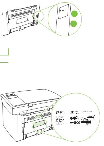
Serial number and model number location
The serial number and product model number label is on the rear of the product.
|
|
|
|
|
|
|
|
|
|
|
|
|
|
|
|
|
|
|
|
|
|
|
|
|
|
|
|
|
|
|
|
|
|
|
|
|
|
|
|
|
|
6 Chapter 1 Product information |
|
|
|
|
|
|
|
ENWW |
|||||

Software description
Supported operating systems
The product supports the following operating systems:
Full software installation |
Print and scan drivers only |
|||
● |
Windows XP (32-bit) |
● |
Windows XP (64-bit) |
|
● |
Windows Vista (32-bit) |
● |
Windows Vista |
(64-bit) |
● |
Windows 2000 |
● Windows 2003 |
Server (64-bit) |
|
●Windows 2003 Server (32-bit)
●Mac OS X v10.3, v10.4, and later
 NOTE: For Mac OS X v10.4 and later, PPC and Intel Core Processor Macs are supported.
Supported printer drivers
The product comes with software for Windows and Macintosh that allows the computer to communicate with the product. This software is called a printer driver. Printer drivers provide access to product features, such as printing on custom-sized paper, resizing documents, and inserting watermarks.
 NOTE: The most recent drivers are available at www.hp.com/support/LJM1120. Depending on the configuration of Windows-based computers, the installation program for the product software automatically checks the computer for Internet access in order to obtain the latest drivers.
Software included with the product
There are several options for completing a recommended install. Easy installation will complete the installation with default settings. Advanced installation allows you to review the license agreements and the default settings.
Easy installation for Windows
●HP drivers
◦Printer driver
◦Scan driver
●HP MFP software
◦HP LaserJet Scan program
◦Uninstall program
●HP Update program
●HP Customer Participation program
ENWW |
Software description 7 |
●Shop for HP Supplies program
●Other programs
◦ Readiris OCR (not installed with other software; separate installation is required)
Advanced installation
Advanced installation includes all of the features that are available with the easy installation. The HP Customer Participation program is optional.
Macintosh software
●HP Product Setup Assistant
●HP Uninstaller
●HP LaserJet software
◦HP Scan
◦HP Director
◦Scan to e-mail program
◦HP Photosmart
8 Chapter 1 Product information |
ENWW |
Software for Windows
Embedded Web server (network models only)
Network models are equipped with an embedded Web server, which provides access to information about device and network activities. This information appears in a Web browser, such as Microsoft Internet Explorer, Netscape Navigator, Apple Safari, or Firefox.
The embedded Web server resides on the device. It is not loaded on a network server.
The embedded Web server provides an interface to the device that anyone who has a networkconnected computer and a standard Web browser can use. No special software is installed or configured, but you must have a supported Web browser on your computer. To gain access to the embedded Web server, type the IP address for the device in the address line of the browser. (To find the IP address, print a configuration page.)
Status Alerts software
The Status Alerts software provides information about the current status of the product.
The software also provides pop-up alerts when certain events occur, such as an empty tray or a problem with the product. The alert includes information about solving the problem.
Other Windows components and utilities
●Software installer — automates the printing system installation
●Online Web registration
ENWW |
Software for Windows 9 |
Software for Macintosh
Embedded Web server (network models only)
Network models are equipped with an embedded Web server, which provides access to information about device and network activities. This information appears in a Web browser, such as Microsoft Internet Explorer, Netscape Navigator, Apple Safari, or Firefox.
The embedded Web server resides on the device. It is not loaded on a network server.
The embedded Web server provides an interface to the device that anyone who has a networkconnected computer and a standard Web browser can use. No special software is installed or configured, but you must have a supported Web browser on your computer. To gain access to the embedded Web server, type the IP address for the device in the address line of the browser. (To find the IP address, print a configuration page.)
HP Director
HP Director is a software program for working with documents. HP Director appears on the computer screen to initiate scanning, or to change settings on the product through Macintosh Configure Device.
Also included is the HP product Setup Assistant, which sets up the print queue.
10 Chapter 1 Product information |
ENWW |
Uninstall software
Windows
1.Click Start, and then click All Programs.
2.Click HP, and then click HP LaserJet M1120.
3.Click Uninstall, and then follow the onscreen instructions to remove the software.
Macintosh
To remove the software, drag the PPD files to the trash can.
ENWW |
Uninstall software 11 |

Media specifications
Supported paper and print media sizes
This product supports a number of paper sizes, and it adapts to various media.
 NOTE: To obtain best print results, select the appropriate paper size and type in the print driver before printing.
Table 1-2 Supported paper and print media sizes
Size |
Dimensions |
Priority input tray |
Tray 1 |
|
|
|
|
Letter |
216 x 279 mm (8.5 x 11 in) |
|
|
|
|
|
|
Legal |
216 x 356 mm (8.5 x 14 in) |
|
|
|
|
|
|
A4 |
210 x 297 mm (8.27 x 11.69 in) |
|
|
|
|
|
|
Executive |
184 x 267 mm (7.24 x 10.51 in) |
|
|
|
|
|
|
A3 |
297 x 420 mm (11.69 x 16.54 in) |
|
|
|
|
|
|
A5 |
148 x 210 mm (5.83 x 8.27 in) |
|
|
|
|
|
|
A6 |
105 x 148 mm (4.13 x 5.83 in) |
|
|
|
|
|
|
B5 (JIS) |
182 x 257 mm (7.17 x 10.12 in) |
|
|
|
|
|
|
16k |
197 x 273 mm (7.75 x 10.75 in) |
|
|
|
|
|
|
16k |
195 x 270 mm (7.7 x 10.6 in) |
|
|
|
|
|
|
16k |
184 x 260 mm (7.25 x 10.25 in) |
|
|
|
|
|
|
8.5 x 13 |
216 x 330 mm (8.5 x 13 in) |
|
|
|
|
|
|
4 x 61 |
107 x 152 mm (4 x 6 in) |
|
|
|
|
|
|
5 x 81 |
127 x 203 mm (5 x 8 in) |
|
|
|
|
|
|
10 x 15 cm1 |
100 x 150 mm (3.9 x 5.9 in) |
|
|
|
|
|
|
Custom |
Priority input tray: Minimum—76 x 127 mm (3 x |
|
|
|
5 in); Maximum—216 x 356 mm (8.5 x 14 in) |
|
|
1 These sizes are supported as custom sizes.
Table 1-3 Supported envelopes and postcards
Size |
Dimensions |
Priority input tray |
Tray 1 |
|
|
|
|
Envelope #10 |
105 x 241 mm (4.13 x 9.49 in) |
|
|
|
|
|
|
Envelope DL |
110 x 220 mm (4.33 x 8.66 in) |
|
|
|
|
|
|
12 Chapter 1 Product information |
ENWW |

Table 1-3 Supported envelopes and postcards (continued)
Size |
Dimensions |
Priority input tray |
Tray 1 |
|
|
|
|
Envelope C5 |
162 x 229 mm (6.93 x 9.84 in) |
|
|
|
|
|
|
Envelope B5 |
176 x 250 mm (6.7 x 9.8 in) |
|
|
|
|
|
|
Envelope Monarch |
98 x 191 mm (3.9 x 7.5 in) |
|
|
|
|
|
|
Postcard |
100 x 148 mm (3.94 x 5.83 in) |
|
|
|
|
|
|
Double postcard |
148 x 200 mm (5.83 x 7.87 in) |
|
|
|
|
|
|
Supported paper types and tray capacity
This product has the following tray priority for feeding print media:
1.Priority input tray
2.Tray 1
Minimum media dimensions are 76 x 127 mm (3 x 5 in).
Maximum media dimensions are 216 x 356 mm (8.5 x 14 in).
To obtain the best print results, change the paper size and paper type settings in the printer driver before printing.
Table 1-4 Supported paper types and tray capacity
Type is |
Media specifications |
Priority input tray |
Tray 1 capacity1 |
Plain |
75 g/m2 (20 lb) to 104 g/m2 (27 lb) |
Up to 10 sheets |
Up to 250 sheets |
Color |
|
|
|
Preprinted |
|
|
|
Prepunched |
|
|
|
Recycled |
|
|
|
|
|
|
|
Light |
60 g/m2 (16 lb) to 75 g/m2 (20 lb) |
Up to 10 sheets |
Up to 260 sheets |
Envelopes |
Less than 90 g/m2 (24 lb) |
1 envelope |
Up to 10 envelopes. |
Labels |
Standard |
1 sheet |
Not supported. |
|
|
|
|
Bond |
75 g/m2 (20 lb) to 104 g/m2 (27 lb) |
1 sheet |
Up to 250 sheets |
Rough |
75 g/m2 (20 lb) to 104 g/m2 (27 lb) |
1 sheet |
Up to 200 sheets |
Transparencies |
4 mm (0.1 in) Monochrome |
1 sheet |
Up to 200 sheets. |
|
Overhead |
|
|
|
|
|
|
Heavy |
110 g/m2 (29 lb) to 125 g/m2 |
Up to 10 sheets |
Not supported. |
|
(33 lb) |
|
|
|
|
|
|
Letterhead |
75 g/m2 (20 lb) to 104 g/m2 (27 lb) |
Up to 10 sheets |
Up to 250 sheets |
1 The maximum stack height for tray 1 is 25 mm (1 inch).
ENWW |
Media specifications 13 |
14 Chapter 1 Product information |
ENWW |
Loading...