


 Loading...
HP LaserJet M1319 MFP Series
Service Manual

HP LaserJet M1319 MFP Series
Service Manual
Copyright information
© 2008 Copyright Hewlett-Packard
Development Company, L.P.
Reproduction, adaptation, or translation without prior written permission is prohibited, except as allowed under the copyright laws.
The information contained herein is subject to change without notice.
The only warranties for HP products and services are set forth in the express warranty statements accompanying such products and services. Nothing herein should be construed as constituting an additional warranty. HP shall not be liable for technical or editorial errors or omissions contained herein.
Part number CB536-90938
Edition 1, 4/2008
Safety information
WARNING!
Potential Shock Hazard
Always follow basic safety precautions when using the product to reduce risk of injury from fire or electric shock.
Read and understand all instructions in the user guide.
Observe all warnings and instructions marked on the product.
Use only a grounded electrical outlet when connecting the product to a power source. If you do not know whether the outlet is grounded, check with a qualified electrician.
Do not touch the contacts on the end of any of the sockets on the product. Replace damaged cords immediately.
Unplug the product from wall outlets before cleaning.
Do not install or use the product near water or when you are wet.
Install the product securely on a stable surface.
Install the product in a protected location where no one can step on or trip over the power cord and where the power cord will not be damaged.
If the product does not operate normally, see the online user guide.
Refer all servicing questions to qualified personnel.
Information regarding FCC Class B, Parts 15 and 68 requirements can be found in the user guide.
Trademark credits
Microsoft® and Windows® are U.S. registered trademarks of Microsoft Corporation.
Windows Vista® is either a registered trademark or trademark of Microsoft Corporation in the United States and/or other countries.
Intel® Core™ is a trademark of Intel Corporation in the U.S. and other countries.

Table of contents
1 Product information |
|
Quick access to product information .................................................................................................... |
2 |
Product configuration ........................................................................................................................... |
3 |
Configuration table ............................................................................................................... |
3 |
Features table ...................................................................................................................... |
3 |
Product walkaround .............................................................................................................................. |
5 |
Front view ............................................................................................................................ |
5 |
Back view ............................................................................................................................. |
6 |
Interface ports ...................................................................................................................... |
6 |
Location of serial number and model number ..................................................................... |
7 |
Supported operating systems ............................................................................................................... |
8 |
Software included with the product ...................................................................................... |
8 |
Easy installation for Windows ............................................................................. |
8 |
Advanced installation .......................................................................................... |
8 |
Macintosh software ............................................................................................. |
9 |
Supported printer drivers ..................................................................................................... |
9 |
Connectivity .......................................................................................................................................... |
9 |
Connect the product directly to a computer with USB ......................................................... |
9 |
2 Control panel |
|
Control panel walkaround ................................................................................................................... |
12 |
Control-panel menus .......................................................................................................................... |
13 |
Use the control-panel menus ............................................................................................. |
13 |
Control-panel main menus ................................................................................................. |
13 |
3 Paper and print media |
|
Supported paper and print media sizes .............................................................................................. |
22 |
Load paper and print media ............................................................................................................... |
23 |
Priority input tray ................................................................................................................ |
23 |
Tray 1 ................................................................................................................................. |
24 |
Configure trays ................................................................................................................................... |
24 |
4 Manage and maintain |
|
Information pages ............................................................................................................................... |
26 |
ENWW |
iii |
Use the HP Toolbox software ............................................................................................................. |
27 |
View HP Toolbox ............................................................................................................... |
27 |
Status ................................................................................................................................. |
27 |
Fax ..................................................................................................................................... |
28 |
Fax tasks ........................................................................................................... |
28 |
Fax phone book ................................................................................................ |
28 |
Fax send log ...................................................................................................... |
30 |
Fax receive log .................................................................................................. |
30 |
Other Links ........................................................................................................................ |
30 |
Manage supplies ................................................................................................................................ |
31 |
Check and order supplies .................................................................................................. |
31 |
Check supplies status by using the control panel ............................................. |
31 |
Store supplies ................................................................................................... |
32 |
HP policy on non-HP supplies ........................................................................... |
32 |
HP fraud hotline ................................................................................................ |
32 |
Recycle supplies ............................................................................................... |
32 |
Replace supplies ............................................................................................................... |
33 |
Print cartridge .................................................................................................... |
33 |
Clean the product .............................................................................................................. |
35 |
Clean the paper path ......................................................................................... |
35 |
Clean the glass and white platen ...................................................................... |
35 |
Clean the exterior .............................................................................................. |
36 |
Firmware updates .............................................................................................................. |
36 |
5 Operational theory |
|
Basic operation ................................................................................................................................... |
38 |
Sequence of operation ...................................................................................................... |
39 |
Sequence of operation, scanner ....................................................................... |
39 |
Sequence of operation, product base ............................................................... |
40 |
Formatter system ............................................................................................................................... |
41 |
Central processing unit ..................................................................................................... |
41 |
Fax card ............................................................................................................................. |
41 |
Standard startup process ................................................................................................... |
42 |
Product startup messages ............................................................................... |
42 |
RAM ................................................................................................................................... |
42 |
USB interface ..................................................................................................................... |
42 |
Control panel ..................................................................................................................... |
42 |
Product base functions ....................................................................................................................... |
43 |
Engine control system (engine control unit and power-supply assembly) ......................... |
44 |
Print-engine control system ............................................................................... |
44 |
Product base laser/scanner .............................................................................. |
45 |
Power system on the power-supply assembly .................................................. |
46 |
AC power distribution ....................................................................... |
46 |
iv |
ENWW |
DC power distribution ....................................................................... |
46 |
Overcurrent/overvoltage ................................................................... |
46 |
High-voltage power distribution ........................................................ |
47 |
Image-formation system .................................................................................................... |
48 |
The seven image-formation processes ............................................................ |
48 |
Print cartridge .................................................................................................................... |
49 |
Product base paper-feed system ....................................................................................... |
49 |
Jam detection in the product ............................................................................................. |
51 |
Conditions of jam detection ............................................................................... |
51 |
HP LaserJet M1319f components ...................................................................................................... |
52 |
Basic operation .................................................................................................................. |
52 |
ADF pickup-and-feed system ............................................................................ |
54 |
Optical scanning system ................................................................................... |
56 |
Fax functions and operation .............................................................................................................. |
58 |
Computer and network security features ........................................................................... |
58 |
PSTN operation ................................................................................................................. |
58 |
Receive faxes when you hear fax tones ............................................................................ |
59 |
Distinctive ring function ...................................................................................................... |
59 |
Fax by using Voice over IP services .................................................................................. |
59 |
The fax subsystem ............................................................................................................. |
60 |
Fax card in the fax subsystem ........................................................................................... |
60 |
Safety isolation .................................................................................................. |
60 |
Safety-protection circuitry .................................................................................. |
60 |
Data path ........................................................................................................... |
61 |
Hook state ......................................................................................................... |
61 |
Downstream device detection ........................................................................... |
61 |
Hook switch control ........................................................................................... |
62 |
Ring detect ........................................................................................................ |
62 |
Line current control ........................................................................................... |
62 |
Billing- (metering-) tone filters ........................................................................... |
62 |
Fax page storage in flash memory .................................................................................... |
62 |
Stored fax pages ............................................................................................... |
62 |
Advantages of flash memory storage ............................................................... |
63 |
6 Removal and replacement |
|
Removal and replacement strategy ................................................................................................... |
66 |
Warnings, cautions, notes, and tips ................................................................................... |
66 |
Electrostatic discharge ....................................................................................................... |
66 |
Required tools ................................................................................................................... |
67 |
Types of screws ................................................................................................................. |
67 |
Service approach ............................................................................................................................... |
68 |
Before performing service .................................................................................................. |
68 |
After performing service ..................................................................................................... |
69 |
ENWW |
v |
Post-service tests .............................................................................................................. |
69 |
Test 1 (print-quality test) ................................................................................... |
69 |
Test 2 (copy-quality test) ................................................................................... |
69 |
Test 3 (fax-quality test) ...................................................................................... |
70 |
Parts removal order ........................................................................................................... |
71 |
Scanner assemblies ........................................................................................................................... |
73 |
Link assemblies and scanner support-frame spring .......................................................... |
73 |
Scanner side covers .......................................................................................................... |
76 |
Separation-pad set ............................................................................................................ |
78 |
Top cover, control panel .................................................................................................... |
79 |
Control-panel assembly ..................................................................................................... |
81 |
Media lever and media-lever torsion spring ....................................................................... |
82 |
Separation-pad assembly .................................................................................................. |
83 |
Scanner assembly ............................................................................................................. |
85 |
Scanner assembly top cover ............................................................................................. |
93 |
Top-cover assembly .......................................................................................................... |
96 |
Pickup roller ....................................................................................................................... |
97 |
White platen ....................................................................................................................... |
98 |
Product base ...................................................................................................................................... |
99 |
Handset ............................................................................................................................. |
99 |
Separation pad ................................................................................................................ |
100 |
Print cartridge .................................................................................................................. |
101 |
Pickup roller ..................................................................................................................... |
102 |
Installing the scanner cushions ........................................................................................ |
105 |
Media input tray ............................................................................................................... |
106 |
Transfer roller .................................................................................................................. |
108 |
Side covers ...................................................................................................................... |
110 |
Print-cartridge door .......................................................................................................... |
112 |
Rear cover and fuser cover ............................................................................................. |
113 |
Front cover ....................................................................................................................... |
115 |
Speaker assembly ........................................................................................................... |
118 |
Power supply ................................................................................................................... |
119 |
Formatter and fax card .................................................................................................... |
122 |
Scanner support-frame .................................................................................................... |
124 |
Engine controller unit (ECU) ............................................................................................ |
127 |
Laser/scanner assembly .................................................................................................. |
131 |
Main motor ....................................................................................................................... |
132 |
Fuser ................................................................................................................................ |
134 |
Paper-pickup assembly ................................................................................................... |
136 |
7 Solve problems |
|
Problem-solving checklist ................................................................................................................. |
138 |
Menu map ........................................................................................................................................ |
140 |
vi |
ENWW |
Print a menu map ............................................................................................................ |
140 |
Tools for troubleshooting .................................................................................................................. |
141 |
Component tests .............................................................................................................. |
141 |
Drum rotation test ............................................................................................ |
141 |
Half self-test functional check ......................................................................... |
142 |
Perform a half self-test check .......................................................................... |
142 |
Perform other checks ...................................................................................... |
142 |
Heating element check .................................................................................... |
143 |
High-voltage contacts check ........................................................................... |
143 |
Check the print-cartridge contacts ................................................ |
143 |
Check the high-voltage connector assembly ................................. |
143 |
Problem-solving diagrams ................................................................................................................ |
144 |
Repetitive image defects ................................................................................................. |
144 |
Component locations ....................................................................................................... |
145 |
Timing diagram, product base ........................................................................................ |
148 |
Main wiring ...................................................................................................................... |
148 |
Formatter PCA and fax card connectors ......................................................................... |
151 |
Control-panel messages .................................................................................................................. |
154 |
Solve control-panel display problems .............................................................................. |
154 |
Alert and warning messages .......................................................................................... |
154 |
Alert and warning message tables .................................................................. |
154 |
Critical error messages .................................................................................................... |
156 |
Critical error message-tables .......................................................................... |
156 |
Solve paper-handling problems ........................................................................................................ |
159 |
Clear jams ........................................................................................................................ |
159 |
Causes of jams ............................................................................................... |
159 |
Where to look for jams .................................................................................... |
160 |
Clear jams from the ADF ................................................................................. |
160 |
Clear jams from the input-tray areas ............................................................... |
161 |
Clear jams from the output bin ........................................................................ |
163 |
Clear jams from the print-cartridge area ......................................................... |
164 |
Avoid repeated jams ...................................................................................... |
165 |
Media-handling problems ................................................................................................ |
165 |
Print-media guidelines ..................................................................................... |
165 |
Solve print-media problems ............................................................................ |
166 |
Performance problems .................................................................................................... |
167 |
Solve image-quality problems .......................................................................................................... |
169 |
Print-quality problems ...................................................................................................... |
169 |
Improve print quality ........................................................................................ |
169 |
Print-quality settings ....................................................................... |
169 |
Checking the print cartridge ........................................................................... |
170 |
To redistribute the toner in the print cartridge ................................. |
170 |
Identify and correct print defects ..................................................................... |
170 |
Print-quality checklist ...................................................................... |
170 |
ENWW |
vii |
General print-quality issues ............................................................ |
170 |
Solve copy problems ........................................................................................................................ |
175 |
Prevent copy problems .................................................................................................... |
175 |
Image problems ............................................................................................................... |
175 |
Media-handling problems ................................................................................................ |
176 |
Performance problems .................................................................................................... |
178 |
Solve scan problems ........................................................................................................................ |
179 |
Solve scanned-image problems ...................................................................................... |
179 |
Scan-quality problems ..................................................................................................... |
180 |
Prevent scan-quality problems ........................................................................ |
180 |
Solve scan-quality problems ........................................................................... |
180 |
Solve control-panel display problems ............................................................................................... |
181 |
Solve connectivity problems ............................................................................................................. |
182 |
Solve direct-connection problems .................................................................................... |
182 |
Solve DSL problems ......................................................................................................................... |
183 |
PBX line problems ........................................................................................................... |
183 |
Solve fax with Voice over IP services problems ............................................................................... |
184 |
Service-mode functions .................................................................................................................... |
185 |
NVRAM initialization ........................................................................................................ |
185 |
Super NVRAM initialization .............................................................................................. |
185 |
Password reset or bypass ............................................................................................... |
185 |
Service menu ................................................................................................................... |
186 |
Secondary service menu ................................................................................................. |
187 |
Solve fax problems ........................................................................................................................... |
188 |
General fax troubleshooting ............................................................................................. |
188 |
Fax error messages ........................................................................................................ |
190 |
Alert and warning message tables .................................................................. |
190 |
Fax memory is retained when there is a loss of power .................................................... |
194 |
Fax logs and reports ........................................................................................................ |
194 |
Print all fax reports .......................................................................................... |
194 |
Print individual fax reports ............................................................................... |
194 |
Set the fax activity log to print automatically ................................................... |
195 |
Set the fax error report .................................................................................... |
195 |
Set the fax confirmation report ........................................................................ |
196 |
Include the first page of each fax on the fax confirmation, fax error, and last |
|
call reports ....................................................................................................... |
196 |
Change error correction and fax speed ........................................................................... |
196 |
Set the fax-error-correction mode ................................................................... |
196 |
Change the fax speed ..................................................................................... |
197 |
Problems sending faxes .................................................................................................. |
197 |
Problems receiving faxes ................................................................................................. |
200 |
Performance problems .................................................................................................... |
202 |
8 Parts
viii |
ENWW |
Ordering information ......................................................................................................................... |
204 |
Supplies and hinge tool .................................................................................................................... |
204 |
Cable and interface accessories ...................................................................................................... |
204 |
Whole unit replacement .................................................................................................................... |
205 |
Control-panel overlay ....................................................................................................................... |
207 |
Supplementary documentation and support ..................................................................................... |
209 |
Parts lists and diagrams ................................................................................................................... |
211 |
Screws ............................................................................................................................. |
211 |
Scanner components and handset ................................................................................................... |
212 |
External assemblies ......................................................................................................... |
212 |
ADF components ............................................................................................................. |
214 |
Frame assembly .............................................................................................................. |
216 |
Guide assembly ............................................................................................................... |
218 |
Product base .................................................................................................................................... |
220 |
External assemblies and print cartridge ........................................................................... |
220 |
External covers ................................................................................................................ |
222 |
Formatter and fax card .................................................................................................... |
224 |
Internal components ........................................................................................................ |
226 |
Alphabetical parts list ....................................................................................................................... |
232 |
Numerical parts list ........................................................................................................................... |
236 |
Appendix A Service and support |
|
Hewlett-Packard limited warranty statement .................................................................................... |
241 |
Customer self repair warranty service .............................................................................................. |
242 |
Print cartridge limited warranty statement ........................................................................................ |
243 |
Customer support ............................................................................................................................. |
243 |
Repack the device ............................................................................................................................ |
244 |
Appendix B Specifications |
|
Physical specifications ..................................................................................................................... |
246 |
Electrical specifications .................................................................................................................... |
246 |
Power consumption .......................................................................................................................... |
246 |
Environmental specifications ............................................................................................................ |
247 |
Acoustic emissions ........................................................................................................................... |
247 |
Appendix C Regulatory information |
|
FCC compliance ............................................................................................................................... |
250 |
Telephone Consumer Protection Act (United States) ...................................................................... |
251 |
IC CS-03 requirements ..................................................................................................................... |
251 |
EU statement for telecom operation ................................................................................................. |
252 |
New Zealand telecom statements .................................................................................................... |
252 |
Declaration of conformity .................................................................................................................. |
253 |
Certificate of Volatility ....................................................................................................................... |
254 |
ENWW |
ix |
Safety statements ............................................................................................................................. |
255 |
Laser safety ..................................................................................................................... |
255 |
Canadian DOC regulations .............................................................................................. |
255 |
EMI statement (Korea) ..................................................................................................... |
255 |
Laser statement for Finland ............................................................................................. |
256 |
Substances table (China) ................................................................................................ |
257 |
Index ................................................................................................................................................................. |
259 |
x |
ENWW |

List of tables
Table 1-1 |
Product guides ................................................................................................................................... |
2 |
Table 2-1 Fax Job status menu ........................................................................................................................ |
13 |
|
Table 2-2 Fax functions menu .......................................................................................................................... |
13 |
|
Table 2-3 Copy setup menu ............................................................................................................................. |
14 |
|
Table 2-4 |
Reports menu ................................................................................................................................... |
14 |
Table 2-5 Fax setup menu ............................................................................................................................... |
15 |
|
Table 2-6 System setup menu ......................................................................................................................... |
18 |
|
Table 2-7 |
Service menu .................................................................................................................................. |
19 |
Table 3-1 Supported paper and print media sizes ........................................................................................... |
22 |
|
Table 3-2 Supported envelopes and postcards ............................................................................................... |
22 |
|
Table 5-1 Basic sequence of operation, scanner ............................................................................................. |
39 |
|
Table 5-2 Basic sequence of operation, product base ..................................................................................... |
40 |
|
Table 5-3 Product startup messages ............................................................................................................... |
42 |
|
Table 5-4 DC power distribution ....................................................................................................................... |
46 |
|
Table 7-1 Repetitive image defects ................................................................................................................ |
144 |
|
Table 7-2 |
Formatter connections ................................................................................................................... |
152 |
Table 7-3 Fax card connections ..................................................................................................................... |
153 |
|
Table 7-4 General fax troubleshooting ........................................................................................................... |
189 |
|
Table 7-5 Alert and warning messages ......................................................................................................... |
190 |
|
Table 8-1 Whole unit replacement, product bundle CB536A ......................................................................... |
205 |
|
Table 8-2 |
Control-panel overlay ..................................................................................................................... |
207 |
Table 8-3 Service and training support .......................................................................................................... |
209 |
|
Table 8-4 |
User guides .................................................................................................................................... |
209 |
Table 8-5 Getting started guide ...................................................................................................................... |
210 |
|
Table 8-6 Technical support Web sites .......................................................................................................... |
210 |
|
Table 8-7 |
Common fasteners ........................................................................................................................ |
211 |
Table 8-8 |
External assemblies ....................................................................................................................... |
213 |
Table 8-9 |
ADF components ........................................................................................................................... |
215 |
Table 8-10 |
Frame assembly ........................................................................................................................... |
217 |
Table 8-11 |
Guide assembly ........................................................................................................................... |
219 |
Table 8-12 External assemblies and print cartridge ....................................................................................... |
221 |
|
Table 8-13 External covers, printer ................................................................................................................ |
223 |
|
Table 8-14 Formatter and fax card ................................................................................................................. |
225 |
|
Table 8-15 Internal components (1 of 3) ........................................................................................................ |
227 |
|
ENWW |
xi |
Table 8-16 Internal components (2 of 3) ........................................................................................................ |
229 |
|
Table 8-17 Internal components (3 of 3) ........................................................................................................ |
231 |
|
Table 8-18 |
Alphabetical parts list ................................................................................................................... |
232 |
Table 8-19 Numerical parts list ....................................................................................................................... |
236 |
|
Table B-1 |
Physical specifications ................................................................................................................... |
246 |
Table B-2 |
Electrical specifications .................................................................................................................. |
246 |
Table B-3 Power consumption (average, in watts) ....................................................................................... |
246 |
|
Table B-4 |
Environmental specifications ........................................................................................................ |
247 |
Table B-5 |
Acoustic emissions ....................................................................................................................... |
247 |
xii |
ENWW |

List of figures
Figure 5-1 Product configuration block diagram .............................................................................................. |
38 |
Figure 5-2 Functional block diagram (product base) ........................................................................................ |
43 |
Figure 5-3 Laser/scanner operation ................................................................................................................. |
45 |
Figure 5-4 High-voltage power supply circuit ................................................................................................... |
47 |
Figure 5-5 Image-formation block diagram ...................................................................................................... |
48 |
Figure 5-6 Product base paper path ................................................................................................................ |
50 |
Figure 5-7 Basic operation block diagram ........................................................................................................ |
52 |
Figure 5-8 Optical and feed systems ................................................................................................................ |
53 |
Figure 5-9 Feed control (1 of 2) ........................................................................................................................ |
54 |
Figure 5-10 Feed control (2 of 2) ...................................................................................................................... |
55 |
Figure 5-11 Optical system (1 of 2) .................................................................................................................. |
56 |
Figure 5-12 Optical system (2 of 2) .................................................................................................................. |
57 |
Figure 6-1 Phillips and pozidrive screwdriver comparison ............................................................................... |
67 |
Figure 6-2 Parts-removal tree, scanner assembly ........................................................................................... |
71 |
Figure 6-3 Parts-removal tree, product base .................................................................................................... |
72 |
Figure 6-4 Removing the link assemblies and scanner support-frame spring (1 of 4) ..................................... |
73 |
Figure 6-5 Removing the link assemblies and scanner support-frame spring (2 of 4) ..................................... |
74 |
Figure 6-6 Removing the link assemblies and scanner support-frame spring (3 of 4) ..................................... |
74 |
Figure 6-7 Removing the link assemblies and scanner support-frame spring (4 of 4) ..................................... |
75 |
Figure 6-8 Removing the scanner side covers (1 of 2) .................................................................................... |
76 |
Figure 6-9 Removing the scanner side covers (2 of 2) .................................................................................... |
77 |
Figure 6-10 Removing the separation pad ....................................................................................................... |
78 |
Figure 6-11 Removing the top cover, control panel (1 of 3) ............................................................................. |
79 |
Figure 6-12 Removing the top cover, control panel (2 of 3) ............................................................................. |
79 |
Figure 6-13 Removing the top cover, control panel (3 of 3) ............................................................................. |
80 |
Figure 6-14 Removing the control-panel assembly (1 of 2) ............................................................................. |
81 |
Figure 6-15 Removing the control-panel assembly (2 of 2) ............................................................................. |
81 |
Figure 6-16 Removing the media lever and media-lever torsion spring ........................................................... |
82 |
Figure 6-17 Removing the separation-pad assembly (1 of 3) .......................................................................... |
83 |
Figure 6-18 Removing the separation-pad assembly (2 of 3) .......................................................................... |
84 |
Figure 6-19 Removing the separation-pad assembly (3 of 3) .......................................................................... |
84 |
Figure 6-20 Removing the scanner assembly (1 of 14) ................................................................................... |
85 |
Figure 6-21 Removing the scanner assembly (2 of 14) ................................................................................... |
85 |
Figure 6-22 Removing the scanner assembly (3 of 14) ................................................................................... |
86 |
ENWW |
xiii |
Figure 6-23 Removing the scanner assembly (4 of 14) ................................................................................... |
86 |
Figure 6-24 Removing the scanner assembly (5 of 14) ................................................................................... |
87 |
Figure 6-25 Removing the scanner assembly (6 of 14) ................................................................................... |
87 |
Figure 6-26 Removing the scanner assembly (7 of 14) ................................................................................... |
88 |
Figure 6-27 Removing the scanner assembly (8 of 14) ................................................................................... |
88 |
Figure 6-28 Removing the scanner assembly (9 of 14) ................................................................................... |
89 |
Figure 6-29 Removing the scanner assembly (10 of 14) ................................................................................. |
89 |
Figure 6-30 Removing the scanner assembly (11 of 14) ................................................................................. |
90 |
Figure 6-31 Removing the scanner assembly (12 of 14) ................................................................................. |
91 |
Figure 6-32 Removing the scanner assembly (13 of 14) ................................................................................. |
92 |
Figure 6-33 Removing the scanner assembly (14 of 14) ................................................................................. |
92 |
Figure 6-34 Removing the scanner assembly top cover (1 of 4) ..................................................................... |
93 |
Figure 6-35 Removing the scanner assembly top cover (2 of 4) ..................................................................... |
94 |
Figure 6-36 Removing the scanner assembly top cover (3 of 4) ..................................................................... |
94 |
Figure 6-37 Removing the scanner assembly top cover (4 of 4) ..................................................................... |
95 |
Figure 6-38 Removing the top-cover assembly (1 of 2) ................................................................................... |
96 |
Figure 6-39 Removing the top-cover assembly (2 of 2) ................................................................................... |
96 |
Figure 6-40 Removing the pickup roller (1 of 2) ............................................................................................... |
97 |
Figure 6-41 Removing the pickup roller (2 of 2) ............................................................................................... |
97 |
Figure 6-42 Removing the white platen (1 of 2) ............................................................................................... |
98 |
Figure 6-43 Removing the white platen (2 of 2) ............................................................................................... |
98 |
Figure 6-44 Remove the handset ..................................................................................................................... |
99 |
Figure 6-45 Removing the separation pad (1 of 2) ........................................................................................ |
100 |
Figure 6-46 Removing the separation pad (2 of 2) ........................................................................................ |
100 |
Figure 6-47 Removing the print cartridge (1 of 2) .......................................................................................... |
101 |
Figure 6-48 Removing the print cartridge (2 of 2) .......................................................................................... |
101 |
Figure 6-49 Removing the pickup roller (1 of 5) ............................................................................................. |
102 |
Figure 6-50 Removing the pickup roller (2 of 5) ............................................................................................. |
102 |
Figure 6-51 Removing the pickup roller (3 of 5) ............................................................................................. |
103 |
Figure 6-52 Removing the pickup roller (4 of 5) ............................................................................................. |
103 |
Figure 6-53 Removing the pickup roller (5 of 5) ............................................................................................. |
104 |
Figure 6-54 Installing the scanner cushions ................................................................................................... |
105 |
Figure 6-55 Removing the media input tray (1 of 3) ....................................................................................... |
106 |
Figure 6-56 Removing the media input tray (2 of 3) ....................................................................................... |
106 |
Figure 6-57 Removing the media input tray (3 of 3) ....................................................................................... |
107 |
Figure 6-58 Removing the transfer roller (1 of 3) ........................................................................................... |
108 |
Figure 6-59 Removing the transfer roller (2 of 3) ........................................................................................... |
109 |
Figure 6-60 Removing the transfer roller (3 of 3) ........................................................................................... |
109 |
Figure 6-61 Removing the side covers (1 of 4) .............................................................................................. |
110 |
Figure 6-62 Removing the side covers (2 of 4) .............................................................................................. |
110 |
Figure 6-63 Removing the side covers (3 of 4) .............................................................................................. |
111 |
Figure 6-64 Removing the side covers (4 of 4) .............................................................................................. |
111 |
Figure 6-65 Removing the print-cartridge door (1 of 2) .................................................................................. |
112 |
Figure 6-66 Removing the print-cartridge door (2 of 2) .................................................................................. |
112 |
xiv |
ENWW |
Figure 6-67 Removing the rear cover and fuser cover (1 of 3) ...................................................................... |
113 |
|
Figure 6-68 Removing the rear cover and fuser cover (2 of 3) ...................................................................... |
113 |
|
Figure 6-69 Removing the rear cover and fuser cover (3 of 3) ...................................................................... |
114 |
|
Figure 6-70 Removing the front cover (1 of 5) ............................................................................................... |
115 |
|
Figure 6-71 Removing the front cover (2 of 5) ............................................................................................... |
115 |
|
Figure 6-72 Removing the front cover (3 of 5) ............................................................................................... |
116 |
|
Figure 6-73 Removing the front cover (4 of 5) ............................................................................................... |
116 |
|
Figure 6-74 Removing the front cover (5 of 5) ............................................................................................... |
117 |
|
Figure 6-75 Removing the speaker assembly (1 of 2) ................................................................................... |
118 |
|
Figure 6-76 Removing the speaker assembly (2 of 2) ................................................................................... |
118 |
|
Figure 6-77 Removing the power supply (1 of 5) ........................................................................................... |
119 |
|
Figure 6-78 Removing the power supply (2 of 5) ........................................................................................... |
119 |
|
Figure 6-79 Removing the power supply (3 of 5) ........................................................................................... |
120 |
|
Figure 6-80 Removing the power supply (4 of 5) ........................................................................................... |
120 |
|
Figure 6-81 Removing the power supply (5 of 5) ........................................................................................... |
121 |
|
Figure 6-82 Removing the formatter (1 of 4) .................................................................................................. |
122 |
|
Figure 6-83 Removing the formatter (2 of 4) .................................................................................................. |
122 |
|
Figure 6-84 Removing the formatter (3 of 4) .................................................................................................. |
123 |
|
Figure 6-85 Removing the formatter (4 of 4) .................................................................................................. |
123 |
|
Figure 6-86 Removing the scanner support-frame (1 of 4) ............................................................................ |
124 |
|
Figure 6-87 Removing the scanner support-frame (2 of 4) ............................................................................ |
125 |
|
Figure 6-88 Removing the scanner support-frame (3 of 4) ............................................................................ |
125 |
|
Figure 6-89 Removing the scanner support-frame (4 of 4) ............................................................................ |
126 |
|
Figure 6-90 Removing the ECU (1 of 6) ......................................................................................................... |
127 |
|
Figure 6-91 Removing the ECU (2 of 6) ......................................................................................................... |
128 |
|
Figure 6-92 Removing the ECU (3 of 6) ......................................................................................................... |
128 |
|
Figure 6-93 Removing the ECU (4 of 6) ......................................................................................................... |
129 |
|
Figure 6-94 Removing the ECU (5 of 6) ......................................................................................................... |
129 |
|
Figure 6-95 Removing the ECU (6 of 6) ......................................................................................................... |
130 |
|
Figure 6-96 Removing the laser/scanner assembly ....................................................................................... |
131 |
|
Figure 6-97 Removing the main motor (1 of 2) .............................................................................................. |
132 |
|
Figure 6-98 Removing the main motor (2 of 2) .............................................................................................. |
133 |
|
Figure 6-99 Removing the fuser assembly (1 of 2) ........................................................................................ |
134 |
|
Figure 6-100 Removing the fuser assembly (2 of 2) ...................................................................................... |
135 |
|
Figure 6-101 Removing the paper-pickup assembly ...................................................................................... |
136 |
|
Figure 7-1 |
Major components ........................................................................................................................ |
145 |
Figure 7-2 Solenoid, sensors, switches, and motor ....................................................................................... |
146 |
|
Figure 7-3 |
PCAs ............................................................................................................................................. |
147 |
Figure 7-4 Timing diagram, product base ...................................................................................................... |
148 |
|
Figure 7-5 Main wiring, scanner assembly ..................................................................................................... |
149 |
|
Figure 7-6 Main wiring, product base (110 V) ................................................................................................ |
150 |
|
Figure 7-7 Main wiring, product base (220 V) ................................................................................................ |
151 |
|
Figure 7-8 |
Formatter connections .................................................................................................................. |
152 |
Figure 7-9 Fax card connections .................................................................................................................... |
153 |
|
ENWW |
xv |
Figure 8-1 |
External assemblies ...................................................................................................................... |
212 |
Figure 8-2 |
ADF components .......................................................................................................................... |
214 |
Figure 8-3 |
Frame assembly ........................................................................................................................... |
216 |
Figure 8-4 |
Guide assembly ............................................................................................................................ |
218 |
Figure 8-5 External assemblies and print cartridge ........................................................................................ |
220 |
|
Figure 8-6 |
External covers ............................................................................................................................. |
222 |
Figure 8-7 Formatter and fax card .................................................................................................................. |
224 |
|
Figure 8-8 Internal components (1 of 3) ......................................................................................................... |
226 |
|
Figure 8-9 Internal components (2 of 3) ......................................................................................................... |
228 |
|
Figure 8-10 Internal components (3 of 3) ....................................................................................................... |
230 |
|
xvi |
ENWW |

1 Product information
●Quick access to product information
●Product configuration
●Product walkaround
●Supported operating systems
●Connectivity
ENWW |
1 |

Quick access to product information
Use the following Web site to find information about the product.
●www.hp.com/support/ljm1319
Table 1-1 Product guides
Guide |
Description |
|
|
HP LaserJet M1319 MFP Getting Provides step-by-step instructions for installing and setting up the product.
Started Guide
HP LaserJet M1319 MFP Series Provides detailed information for using the product and problem-solving. Available on the
User Guide |
product CD or in the Windows Program Group if the software is installed on a computer. |
|
|
HP ToolboxFX |
To check the product status and settings, and to view problem-solving information and online |
|
documentation, use the HP ToolboxFX. You must have performed a complete software |
|
installation in order to use the HP ToolboxFX. See the user guide for more information about |
|
software installation. |
|
|
Online Help |
Provides information about options that are available in the printer drivers. To view a Help |
|
file, open the online Help through the printer driver. |
|
|
2 Chapter 1 Product information |
ENWW |
Product configuration
Configuration table
HP LaserJet M1319f MFP
●Prints letter-size pages at speeds up to 19 pages per minute (ppm) and A4-size pages at speeds up to 18 ppm.
●Tray 1 holds up to 250 sheets of print media or up to 10 envelopes.
●The priority input tray holds up to 10 sheets of print media.
●Manual two-sided (duplex) printing, fax receiving, and copying.
●Average yield for the standard black print cartridge is 2,000 pages, in accordance with ISO/IEC 19752. Actual yield depends on specific use.
●Hi-Speed USB 2.0 port and one telephone handset port.
●V.34 fax modem and 4-megabyte (MB) flash fax-storage memory.
●Two RJ-11 fax phone cable ports.
●32-MB random-access memory (RAM).
●30-page automatic document feeder (ADF).
●Integrated telephone handset.
Features table
Performance |
● Prints letter-size pages at speeds up to 19 ppm and A4-size pages at speeds up to 18 ppm. |
|
|
Print quality |
● Prints at 600 dots per inch (dpi) and FastRes 1200 dpi. |
|
● Includes adjustable settings to optimize print quality. |
|
|
Fax |
● Full-functionality fax capabilities with a V.34 fax; includes a phone book, fax/tel, and |
|
delayed-fax features. |
|
● 4 MB flash fax-storage memory. |
|
|
ENWW |
Product configuration 3 |

Copy |
● Copies at 300 dots per inch (dpi). |
|
|
Scan |
● Provides 600 pixels per inch (ppi) full-color scanning. |
|
|
Memory |
● Includes 32-megabyte (MB) random-access memory (RAM). |
|
|
Paper handling |
● 30–page ADF. |
|
● Priority input tray holds up to 10 pages. |
|
● Tray 1 holds up to 250 sheets of print media or 10 envelopes. |
|
● Output bin holds up to 100 sheets of print media. |
|
|
Printer driver features |
● FastRes 1200 produces 1200-dots-per-inch (dpi) print quality for fast, high-quality printing |
|
of business text and graphics. |
|
|
Interface connections |
● Hi-Speed USB 2.0 port. |
|
● Two RJ-11 fax/phone cable ports. |
|
|
Economical printing |
● N-up printing (printing more than one page on a sheet). |
|
● Manual two-sided printing, faxing, and copying. |
|
● EconoMode setting (uses less toner). |
|
|
Supplies |
● The product ships with a 1,000-page (average yield) starter cartridge. The average yield |
|
for replacement cartridges is 2,000 pages, in accordance with ISO/IEC 19752. |
|
|
Telephone handset |
A integrated telephone handset for making and receiving voice calls at the product. |
|
|
Accessibility |
● Online user guide that is compatible with text screen-readers. |
|
● Print cartridges can be installed and removed using one hand. |
|
● All doors and covers can be opened using one hand. |
|
|
4 Chapter 1 Product information |
ENWW |
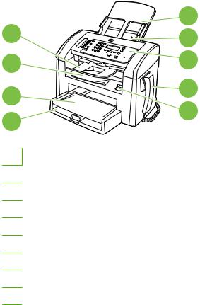
Product walkaround
Front view
4 |
5 |
|
6 |
||
3 |
7 |
|
2 |
8 |
|
9 |
||
1 |
||
|
1Tray 1
2Priority input tray
3Output bin
4Automatic document feeder (ADF) output bin
5Automatic document feeder (ADF) input tray
6ADF media lever
7Control panel
8Telephone handset
9Print-cartridge door latch
ENWW |
Product walkaround 5 |

Back view
11 |
12 |
|
10
 13
13
10Interface ports
11Kensington lock
12Power switch
13Power connector
Interface ports
The product has a Hi-Speed USB 2.0 port, fax and phone ports, and a handset port.
1

2
3

1Handset port
2Hi-Speed USB 2.0 port
3Fax ports
6 Chapter 1 Product information |
ENWW |

Location of serial number and model number
|
|
|
|
|
|
|
|
|
|
|
|
|
|
|
|
|
|
|
|
|
|
|
|
|
|
|
|
|
|
|
|
|
|
|
|
|
|
|
|
|
|
|
|
|
|
|
|
|
|
|
|
|
|
|
|
|
|
|
|
|
|
|
|
|
ENWW |
|
|
|
|
|
Product walkaround 7 |
||||||

Supported operating systems
The product supports the following operating systems: |
|
||
Full software installation |
Print and scan drivers only |
||
● Windows® XP (32-bit and 64-bit) |
● |
Windows XP (64-bit) |
|
● |
Windows Vista® (32-bit) |
● |
Windows Vista (64-bit) |
● |
Mac OS X v10.3, v10.4, and later |
● |
Windows 2000 |
● Windows 2003 Server (32-bit and 64-bit)
 NOTE: For Mac OS X v10.4 and later, PPC and Intel® Core™ Processor Macs are supported.
Software included with the product
There are several options for completing a recommended installation. Easy Install will complete the installation with default settings. Advanced Install allows you to select custom settings and choose the components that are installed.
Easy installation for Windows
●HP drivers
◦Printer driver
◦Scan driver
◦Fax driver
●HP MFP software
◦HP LaserJet Scan program
◦HP Fax Send Fax program
◦HP Toolbox program
HP Toolbox provides links to product status information and Help information, such as the user guide, and tools for product problem-solving.
◦Uninstall program
●Other programs
◦Readiris OCR (not installed with other software; separate installation is required)
Advanced installation
Advanced installation includes all of the features that are available with the easy installation. The HP Customer Participation program is optional.
8 Chapter 1 Product information |
ENWW |

Macintosh software
●HP Product Setup Assistant
●HP Uninstaller
●HP LaserJet software
◦HP Scan
◦HP Director
HP Director is a software program for working with documents. When the document is loaded into the ADF and the computer is connected directly to the product, HP Director appears on the computer screen to initiate faxing, scanning, or changing settings on the product through Macintosh Configure Device.
HP Director also includes the HP product Setup Assistant for setting up fax and print queues.
◦Scan to e-mail program
Supported printer drivers
The most recent drivers are available at www.hp.com/support/ljm1319. Depending on the configuration of Windows-based computers, the installation program for the product software automatically checks the computer for Internet access to obtain the latest drivers.
Connectivity
Connect the product directly to a computer with USB
 NOTE: Do not connect the USB cable from the product to the computer until the installer prompts you to do so.
1.Insert the product CD into your computer. If the software installer does not start, navigate to the setup.exe file on the CD and double-click the file.
2.Follow the installer instructions.
3.Allow the installation process to complete, and then restart the computer.
ENWW |
Connectivity 9 |
10 Chapter 1 Product information |
ENWW |

2 Control panel
●Control panel walkaround
●Control-panel menus
ENWW |
11 |

Control panel walkaround
1 |
2 |
3 |
4 |
1Fax controls. Use to change commonly used fax settings.
2Alphanumeric buttons. Use to type data into the product control-panel display and to dial telephone numbers for faxing.
3Setup and cancel controls. Use to select menu options, determine the product status, and cancel the current job.
4Copy controls. Use to change commonly used default settings and to start copying.
12 Chapter 2 Control panel |
ENWW |
Loading...