


 Loading...
DESIGNJET L28500 Printer Series
January 2012
For HP Internal Use Only
© 2012 Hewlett-Packard Company
This document contains proprietary information that is protected by copyright. All rights are reserved. No part of this document may be photocopied, reproduced, or translated to another language without the prior written consent of Hewlett-Packard Company.
1st Edition, January 2012
Customer Assurance Customer Experience Section Large Format Printing Division Hewlett-Packard Espanola, S.L. Cami de Can Graells, 1–21 08174 Sant Cugat del Vallès Spain
Warranty
The information contained in this document is subject to change without notice.
Hewlett-Packard makes no warranty of any kind with regard to this material, including, but not limited to, the implied warranties of merchantability and fitness for a particular purpose.
Hewlett-Packard shall not be liable for errors contained herein or for incidental or consequential damages in connection with the furnishing, performance, or use of this material.
WARNING
The procedures described in this manual are to be performed by HP-qualified service personnel only.
Electrical Shock Hazard
Serious shock hazard leading to death or injury may result if you do not take the following precautions:
-Ensure that the ac power outlet (mains) has a protective earth (ground) terminal.
-Disconnect the printer from the power source before performing any maintenance.
-Prevent water or any other liquids from running onto electrical components or circuits, or through openings in the enclosure.
Electrostatic Discharge
Refer to the beginning of Chapter 4 of this manual, for precautions you should take to prevent damage to the printer circuits from electrostatic discharge.
Safety Symbols
General definitions of safety symbols are given immediately after the table of contents.
WARNING
The Warning symbol calls attention to a procedure, practice, or the like, which, if not correctly performed or adhered to, could result in personal injury. Do not proceed beyond a Warning symbol until the indicated conditions are fully understood and met.
CAUTION
The Caution symbol calls attention to an operating procedure, practice, or the like, which, if not correctly performed or adhered to, could result in damage to or destruction of part or all of the product. Do not proceed beyond a Caution symbol until the indicated conditions are fully understood and met.
HP Designjet L28500 Printer Series
Service Manual
Table of Contents
Printer system 1-7
Troubleshooting 2-43
System error codes 3-83
Service test, utilities and calibrations 4-139 Print quality 5-201
Ink supplies 6-229
Service parts and diagrams 7-239 Removal and installation 8-263 Preventive maintenance 9-591
Move, repack, and store the printer 10-595 Safety precautions 11-607
Using this manual
Purpose
This Service Manual contains information necessary to test, calibrate, and service the HP Designjet L28500 104-inch Printer (Model CQ871A).
For information about using the printer, see the User’s Guide.
Chapters
1 Printer systems
Use this chapter as a reference for technical information about the subsystems, components, and how they work together.
Of particular importance are the diagrams included for each subsystem of the printer. They can be useful for both troubleshooting and disassembly.
2 Troubleshooting
Whenever a printer is not functioning correctly due to a fault, use this chapter for step-by-step diagnosis until you arrive at the solution, which may include replacing a part.
Troubleshooting always begins with a problem; so, when you enter the chapter, navigate to the proper section and find the troubleshooting steps for your problem.
This chapter does not cover the procedures for the diagnostic tests you must perform while troubleshooting, nor the replacement procedures you must complete to fix the problem.
3 System error codes
This chapter contains the system error codes which are displayed on the Front Panel and by the Embedded Web Server. Each system error code shown in the chapter has a brief description and the steps required to solve the error.
Most of the troubleshooting steps involve performing a test or a calibration, which can be found in the following chapter. Before replacing any part that you suspect of causing the system error code, always perform the test or calibration.
4 Tests, utilities, and calibrations
Use this chapter whenever you need to perform a diagnostic test, service utility, or service calibration. This chapter is meant to provide procedures and relevant information, not troubleshooting information. For troubleshooting information, see the Troubleshooting chapter.
These procedures are described in full, so that you know any relevant values for the test, as well as information about what the printer is actually doing during the test.
The goal of diagnostic tests is to locate the root cause of the problem and the corresponding system error code or message that will provide you with logical steps to resolution.
Some diagnostic tests or calibrations must be performed after removing a component.
5 Print quality
This chapter describes the print-quality diagnostic procedures. Further troubleshooting advice can be found in the User’s Guide.
6 Ink supplies
This chapter describes and discusses the components of the ink supply system.
7 Parts and diagrams
The purpose of this chapter is to detail all of the available service parts of the printer. This information is presented in tables, organized by subsystem, and includes the following:
•Official service part names
•Part numbers
•Illustrations of the service parts
Use this chapter whenever you need to order a service part.
8 Removal and installation
The purpose of this chapter is to provide procedures for removing and installing service parts. Each service part has a removal procedure detailed in this chapter, and installation procedures and notes are included as needed.
Useful information such as access notes and screw types (head sizes) are provided to help you work efficiently.
9 Preventive maintenance
Maintenance alerts are displayed on the Front Panel and Embedded Web Server whenever maintenance is required. While most of these alerts can be resolved by the customer, some require a service engineer.
Use the preventive maintenance chapter whenever you need to perform a preventive maintenance procedure due to an alert the customer receives from the Front Panel or Embedded Web Server, or to get reference information on life counters and maintenance that must be performed by the customer.
10 Move, store, or repack the printer
This chapter gives advice on moving, storing, and repacking the printer.
11 Safety precautions
This is an industrial printer that uses high voltages: service operations can be hazardous. The safety chapter covers all the guidelines and checks you need to perform in order to service the printer.
You are expected to have appropriate technical training and experience necessary to be aware of hazards to which you may be exposed in performing a task, and take appropriate measures to minimize the risks to yourself and to other people.
Readership
The primary readers of this service manual are HP Service Engineers, although secondary readership may include resellers. All procedures must be performed by HP Service Engineers or Authorized Service Delivery Partners, except for those procedures clearly marked otherwise.

1 Printer systems
Printer Systems
• |
Electrical system ..................................................................................................... |
8 |
• |
Substrate path ..................................................................................................... |
23 |
• Ink Delivery System (IDS) ....................................................................................... |
29 |
|
• Scan Axis and Carriage........................................................................................ |
31 |
|
• Service Station and Waste management ................................................................. |
34 |
|
• |
Heating system .................................................................................................... |
38 |
• |
Front Panel .......................................................................................................... |
41 |
Printer systems |
7 |

Printer systems
Electrical system
Description
The electrical system controls all the printing systems and the heating systems inside the printer. Most parts of the control electronics are placed inside the ’E-box’.
Components
The electronics can be divided into different functional subsystems and will be described accordingly. There are 7 functional subsystems within the electronics, as shown below.
•Front Panel: The Front Panel in this printer includes a touchscreen, a power button, and a buzzer. It is connected to three different boards on the EEbox: Formatter PCA (control), Engine PCA (power button signal), and Mini Interconnect PCA (buzzer and power control).
•Substrate Path: Controls the substrate movement: Drive Roller and Rewinder motors, Take-Up Reel, OMAS sensor, four Vacuum Fans (controlled by two Eola PCAs), pinch lever, and Media Sensors.
•Scan Axis: Printhead firing control and sensors for color and substrate detection (Carriage PCA, encoder, Tetris and SOL sensors, substrate crash sensor, and movement control using the scan motor and its fan).
•Service Station: Printhead maintenance. It controls a motor, a drop detector, and some sensors, including primer.
•Waste Management: Management of the waste ink and aerosol coming from the Service Station.
•Ink Supply: Control of ink through two ISS PCAs and an intermediate PreDriver board as a buffer.
•Heating System: Dryer and Curing Resistor heater elements controlled by three sinewave converters plus some Infrared (IR) sensors for Latex ink. The power input lines for the heating are distributed to the rest of the printer through the EE Cabinet module.
8 |
Printer systems |

Circuit diagram
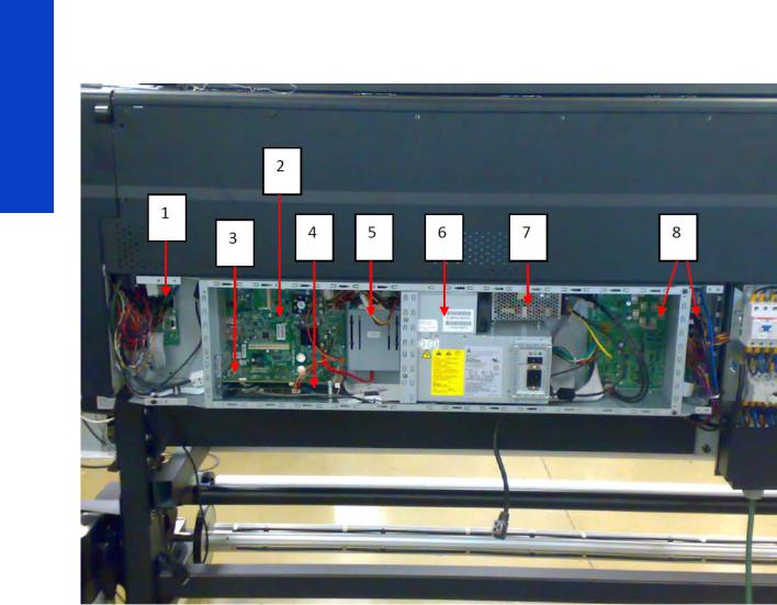
E-box components
Description
The E-box contains most of the electronics of the printer.
Printer systems
Printer systems |
9 |
Printer systems
Components
1.Mini interconnect PCA [Messi]
2.Formatter PCA [Torus]
3.Engine PCA [Tokamak] (similar to what was known as Sausalito)
4.OMAS PCA
5.Hard Disk Drive (HDD)
6.Power Supply Unit (PSU)
7.Extra Power Supply 24 V
8.Printmech PCA [Boomerang]
Functionality
Mini interconnect PCA
The Mini PCA is just a interconnect board with only connectors that helps distribute the power and control signals from the Printmech board to all the elements connected to the right side of the machine, including the following:
•Take-Up Reel
•Vacuum Fans (passes through, the actual control is inside Printmech)
•Front Panel
•TOMAS (temperature sensor for the OMAS sensor)
10 |
Printer systems |
•Valves and motors for primer, rack engage, SVS, and Waste Management
•Top fans
•Rewinder motor
Formatter Main PCA
The formatter is the motherboard of the printer, referred to as the Main Board, and is the same type as for a standard PC.
Engine PCA
This board is the main controller of the printer. It is responsible for all the processes performed in real-time and is the ultimate controller of all electromechanical systems. The Engine PCA controls all substrate path components (Drive Roller, Spindle Motors, OMAS, etc.) and all non-substrate path components (Carriage, Scan Axis Motor, Dryer and Curing Heaters, Print Head Cleaning Assembly, Service Station, etc).
OMAS PCA
This board controls the Optical Media Advance Sensor used to measure the substrate advance.
Hard Disk Drive (HDD)
The HDD contains the firmware of the printer.
•The operating system.
•All calibration values, product number, serial number etc, are stored on the Hard Disk Drive. In order to make sure that this information is not lost in the case of a failure of the HDD, a backup is made in the ISS top board
NOTE: In order to prevent any loss of calibration values, do not replace the following at the same time:
•The Hard Disk Drive and the ISS Top Board
Power Supply Unit (PSU)
This PSU delivers power to all the parts of the printer but the heater elements. The internal rails are: 5V_sb; 3V3, 5V, 12V, 24V, and 42V.
Extra Power Supply Unit (24 V)
This extra PSU supplies 24 V for some extra components such as drying fans and scan motor fan.
Printmech PCA [Boomerang]
The Printmech PCA is mainly used to control all the mechatronics of the printer. For routing reasons, only the parts connected to the left side of the printer are connected to this board:
•Scan-Axis Motor
•Media-Axis Motor
•Ink valves
•Ink pressurizing pumps
•Dryer fans
•Curing fan
•Vacuum fans
•IR sensor
•IR Fan
•Sinewave converter control
•Media Jam Sensor
Printer systems
Printer systems |
11 |
Printer systems
The remaining functionality implemented in the printmech PCA is sent to the right side of the printer through the Mini Interconnect PCA and its 3 cables (power + data).
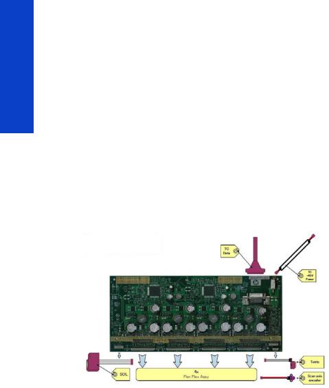
Carriage Electronics
The Carriage contains the electronics for controlling and firing the Printheads. It also contains electronics for controlling the external sensors (SOL and Tetris) as well as the Scan Axis Encoder.
The electronics of the Carriage receives power and data from the Trailing cables, which conveys both Power (+45V) and Data (LVDS) cables. The Power cable connects the Carriage with the Printmech board and Data cable connects Carriage with the Main (Engine) board)
Components
Carriage PCA
The Carriage PCA contains the electronics to control how and when the ink is dropped from every Printhead, and receives information from the sensors.
SOL Spectrophotometer
The SOL is a color sensor located on the left side of the Carriage. A metal sheet protects the SOL from the high temperatures produced by the Dryer Assembly. The main function of the SOL is to measure color samples that have been printed on the loaded substrate and then are placed in the print platen zone.
Before taking any color measurement, the SOL must be initialized. The SOL initialization process takes approximately 7 minutes. This process consists of three steps:
•Sensor switch on
•Sensor warm up
•Sensor calibration
When the initialization process has finished, the shutter opens automatically and the Carriage is moved along the Scan Axis to place the SOL on top of each sample to take a color measurement. After the measurements, the shutter is closed again and the sensor is switched off.
Tetris
Tetris is used to align the Printheads as well as to locate the substrate edges and measure its size. The alignment procedure consists of a series of patterns first being printed, then scanned using the Tetris, and finally an internal process is used to correct the timing of when and where the nozzles of the Printheads fire, and detect any possible nozzle-out issues.
Scan axis encoder
12 |
Printer systems |
The line encoder is located on the Carriage; it measures and counts the movements of the Scan Axis. An optical, infrared wavelength encoder is used: the same type of encoder used in most of the HP large-format printers. The Encoder signal is converted to LVDS logic levels and directly routed through the Data TC.
Printhead Flex
To connect the Carriage to the Printheads, a delicate flexible circuit with small golden dimples is used. Printheads are inserted into unique slots and a spring-loaded mechanism pushes the electrical contacts of the Printheads into the Printhead flex, which subsequently connects the Printhead to the Carriage electronics. Printhead Flexes are the most delicate and sensitive part of the Carriage. If the Printheads are inserted with too much force or they are misaligned, the insertion can easily damage them.
Ink Supply Station (ISS) Electronics
Description
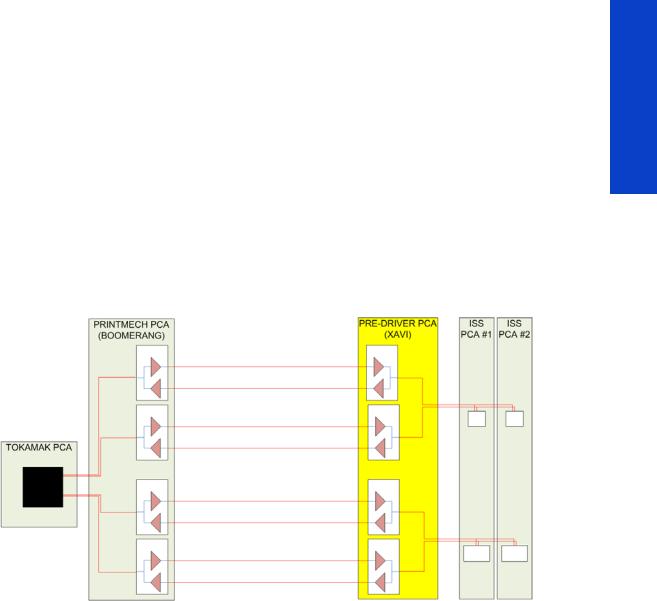
There are two ISS PCAs (as in the DJ L25500/L26500 printers) plus a new extra board in between the ISS PCAs and the PrintMech PCA, called the Pre-Driver PCA.
Printer systems
Printer systems |
13 |
Printer systems
Components
PreDriver PCA
This board receives signals from the PrintMech PCA in differential mode and translates them to singleended ones.
It has two LEDS:
•Green LED: 5 V present coming from the PrintMech board (cable connected)
•Red LED: Overpressure or disconnected cable to the ISS PCA
See the Troubleshooting chapter (page 50) for more details, such as the location of the LEDs.
Top and Lower ISS PCAs
The ISS electronics are powered from a +12 V line coming from the PrintMech, and a linear regulator on the ISS PCAs generates the +5 V used to power all the devices on the board.
The ISS PCAs are two electronic PCAs located at the rear of the Ink Supply Station. The ISS PCAs provide the following:
•Pressure Ink Level Sense (PILS) measurement
•Ink supply presence detection
•Ink Cartridge broken bag detection
•Ink supply smart chip interface
•Air pressure measurement and air pump shutdown
•Humidity and temperature measurements
•System back-up EEPROM
14 |
Printer systems |
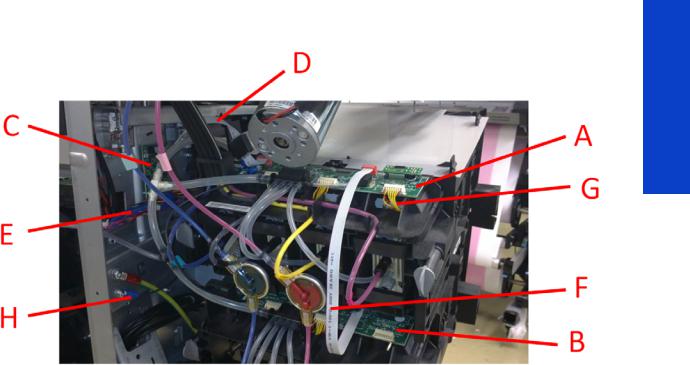
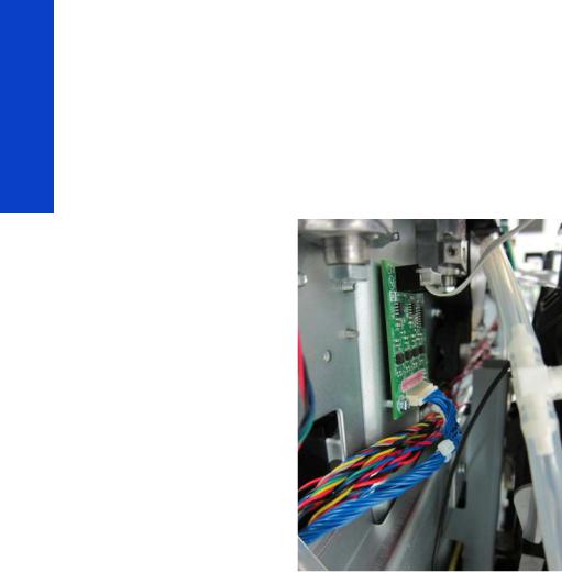
Below is a picture showing the connections and components located at the rear of the ISS.
Marking |
Description |
|
|
A |
ISS Top PCA |
|
|
B |
ISS Lower PCA |
|
|
C |
Pre-Driver PCA |
|
|
D |
Cable: ISS Top PCA to Pre-Driver PCA |
|
|
E |
Cable: Pre-Driver PCA to PrintMech PCA (blue) |
|
|
F |
Cable: ISS Top PCA to ISS Lower PCA |
|
|
G |
Cables (6): ISS PCAs (Top and Lower) to Ink Cartridges |
|
|
H |
ISS grounding cable |
|
|
Both top and lower ISS PCAs share the same PCB, the only difference between them is that the lower PCA is a simplification of the top PCA: the top PCA contains these additional parts:
•EEPROM
•Connection from the PrintMech PCA
•Air pressure sensor
•Temperature and Humidity sensors
Both PCAs are connected through an 8-pin connector. The 2nd ISS connector is connected to the PrintMech PCA in a daisy-chained connection, the 1st ISS board by means of this 8-pin connector.
Vacuum Fan electronics
Description
There are two Eola PCAs to control 4 different brushless blowers in order to generate the required vacuum to hold the substrate. One of the Eola PCAs is connected to the Printmech PCA (left side of the printer) and the other one to the Mini Interconnect PCA (right side).
Printer systems
Printer systems |
15 |
Printer systems
Waste Management Electronics
Description
There is a small interconnect board (WM PCA) to connect the aerosol fan and two switches used in the waste management system (as in the DJ L26500). This board is connected to the EEbox through the Mini Interconnect PCA. There is an intermediate connector in the Ebox chassis to allow customers to connect the cable during installation.
Heating System Electronics
Description
The heating system provides the power to the heater elements in order to dry and cure the jobs.
The amount of power used for heating requires a three-phase power system.
Components
•Terminal block
•Main Switch
•3 x RCBs
•3 x Sine wave converters
•Drying & curing resistors
•Thermal switches
•IR sensors (for curing and heating)
•IR sensor curing cooling fan
•2 x Window switches x Sine wave converters
•Curing and Drying fans
INPUT Circuit diagrams
The heating components form a high voltage system, so they are protected by their own enclosure (EE cabinet) for safety.
16 |
Printer systems |
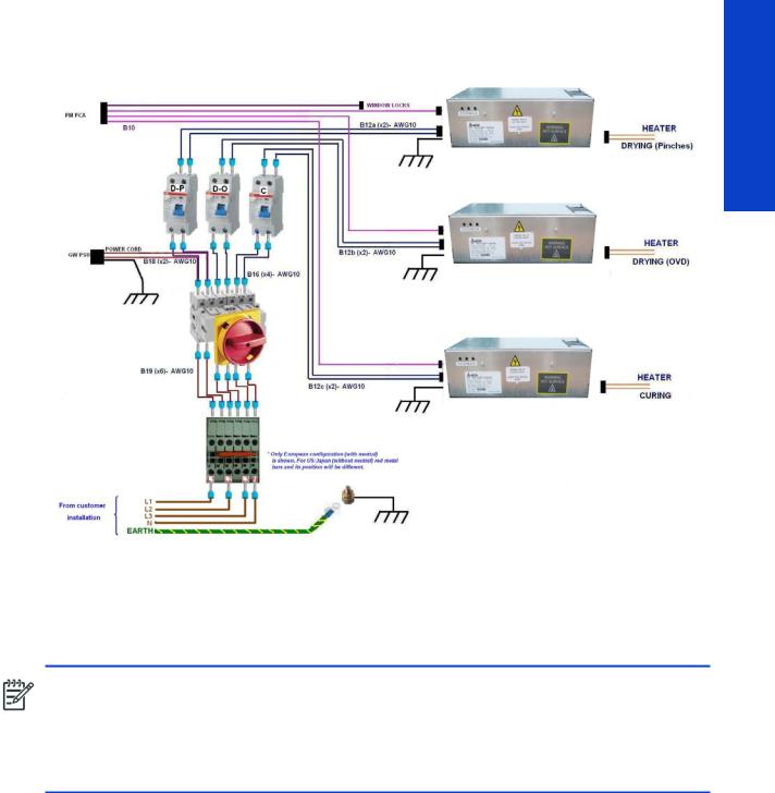
A simplified block diagram of the input stage of the heater system (EE cabinet) is shown in the following picture:
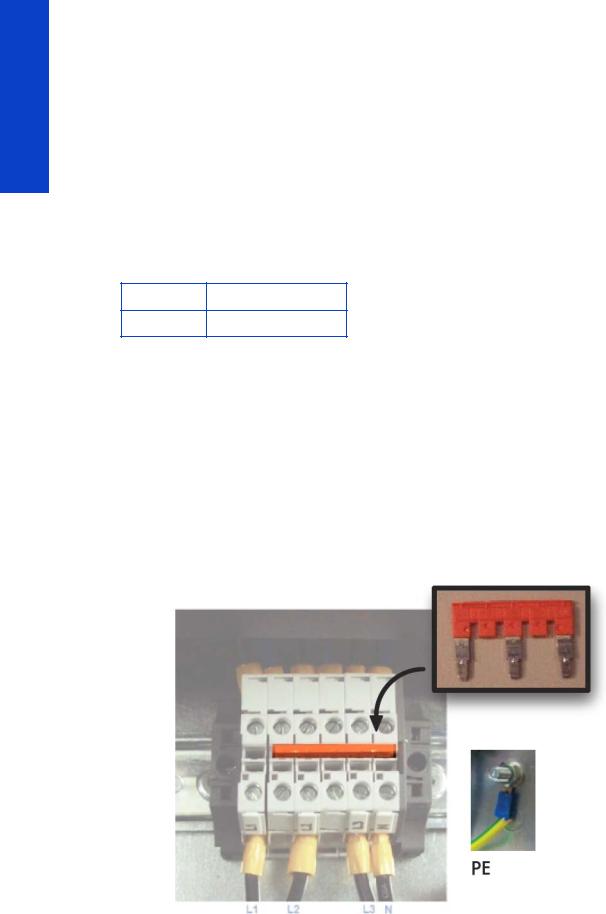
Terminal block
The terminal block is used to configure the printer depending on the customer's mains configuration. It has some jumpers used to perform the configuration. The input power cables from the customer's installation (not provided with the printer) are connected within this terminal block.
NOTE: An electrician is required for the setup and configuration of the building's electrical system used to power the printer and also for printer installation. Make sure that your electrician is appropriately certified according to local regulations and supplied with all the information regarding the electrical configuration.
Remember that you are required to follow the local laws, regulations and standards that pertain to the electrical installation of your printer.
Electrical power system
The printer requires three-phase power, which provides a more efficient means of supplying large electrical loads than single-phase power. There are two possible configurations depending on input voltage range, as described below.
Printer systems
Printer systems |
17 |
Printer systems
380–415 V three-phase line-to-line configuration
Three-phase line specifications
Number of power wires |
5 (3 lines + 1 neutral + 1 PE) |
|
|
Input voltage (line-to-line) |
380–415 V (–10%+6%) |
|
|
Input frequency |
50/60 Hz |
|
|
Power consumption |
8 kW |
|
|
Maximum load current (per phase) |
24 A |
|
|
Circuit-breaker specifications
Branch circuit-breaker
Three-phase 4 poles, 30–32 A
AC power cable specifications
|
Three-phase line |
|
|
Configuration |
5 wires, L1/L2/L3/N/PE |
|
|
Wire |
Strained Cu, minimum 4 mm² or 10 AWG |
|
|
Terminals |
Lines: ferrule terminals, PE: M6 ring terminal |
|
|
External diameter range |
15–25 mm |
|
|
Jumper configuration
18 |
Printer systems |
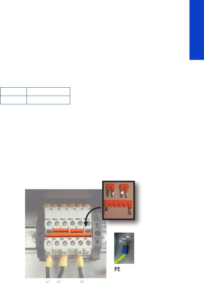
200–240 V three-phase line-to-line configuration
Three-phase line specifications
Number of power wires |
4 (3 lines + 1 PE) |
|
|
Input voltage (line-to-line) |
200–240 V (±10%) |
|
|
Input frequency |
50/60 Hz |
|
|
Power consumption |
8 kW |
|
|
Maximum load current (per phase) |
40 A |
|
|
Circuit-breaker specifications
Branch circuit-breaker
Three-phase 3 poles, 50 A
AC power cable specifications
|
Three-phase line |
|
|
Configuration |
4 wires, L1/L2/L3/PE |
|
|
Wire |
Strained Cu, minimum 6 mm² or 8 AWG |
|
|
Terminals |
Lines: ferrule terminals, PE: M6 ring terminal |
|
|
External diameter range |
15–25 mm |
|
|
Jumper configuration
Printer systems
Printer systems |
19 |
Printer systems
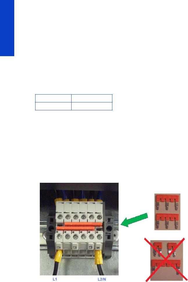
200–240 V single-phase or bi-phase line-to-line configuration
If the customer cannot connect to a three-phase system, it is still possible to connect to a bi-phase or singlephase installation if the following requirements of current rating are met (approved by electrician).
Singleor bi-phase line specifications
Number of power wires |
3 (2 lines + 1 PE) |
|
|
Input voltage (line-to-line) |
200–240 V~ (±10%) |
|
|
Input frequency |
50/60 Hz |
|
|
Power consumption |
8 kW |
|
|
Maximum load current (per phase) |
48 A |
|
|
Circuit-breaker specifications
Branch circuit-breaker
Singleor bi-phase 2 poles, 60/63 A
AC power cable specifications
|
Singleor bi-phase line |
|
|
Configuration |
3 wires, L1/N/PE or L1/L2/PE |
|
|
Wire |
Strained Cu, minimum 10 mm² or 6 AWG |
|
|
Terminals |
Lines: ferrule terminals, PE: M6 ring terminal |
|
|
External diameter range |
14–25 mm |
|
|
Jumper configuration
20 |
Printer systems |
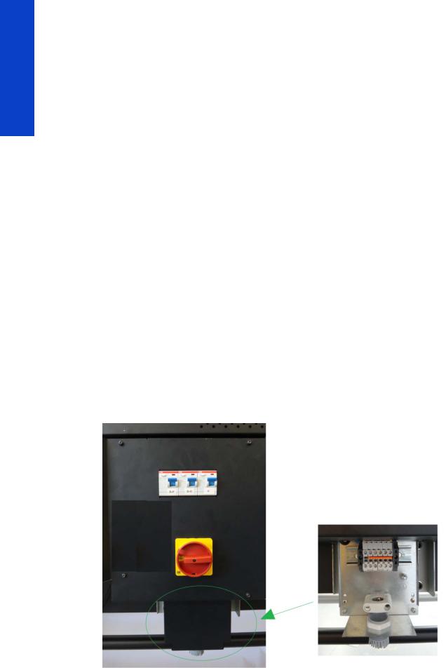
Main Switch
The Main Switch is used to switch the whole printer on or off, including all the printer electronics.
Residual Circuit Current Breaker (RCCB)
To protect the printer and the users, there are three Residual Circuit Current Breakers (RCCB), which are connected between two power inputs and the Sine Wave Converter module. They detect a current leak greater than 30mA. Customers can reset the RCCB if a circuit blows, but a frequent reoccurrence indicates an electrical failure in one or more of the heaters.
Sinewave converters
These three modules convert the input voltage from the mains to a voltage in the output that is controlled by the EEbox depending the quantity of power required to each of the resistors connected to them.
Each converter has three cables: One power cable for the input, another one for the output power, and finally the control cable. The control part of the converter that interfaces with the Printmech is powered at 24 V from the printmech PCA through the control cable and through both switches placed in the window cover of the printer. This cover has to be closed to allow the converters to work.
Each converter has 3 LEDs: Status (off or fault), PWM (if power is being delivered to the output) and ACOK (if Vin is in range).
Printer systems
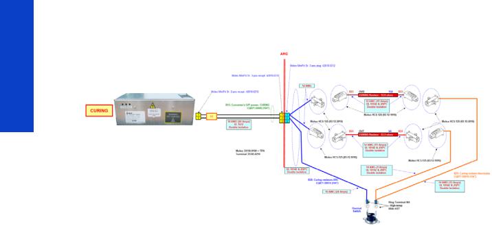
Output circuit diagrams
The following diagrams show the connections between the converters and the heating elements.
Drying
Printer systems |
21 |
Printer systems
Curing
22 |
Printer systems |
Substrate path
Description
The substrate path moves the substrate from the input spindle to the take-up reel, through the print path, while the Carriage prints on the substrate. The objectives of the substrate path while advancing the substrate are:
•Maintain an accurate advance
•Maintain a constant advance
•Keep the substrate flat
•Advance the substrate straight along the substrate axis
Substrate path workflow overview
The following steps describes the substrate path workflow.
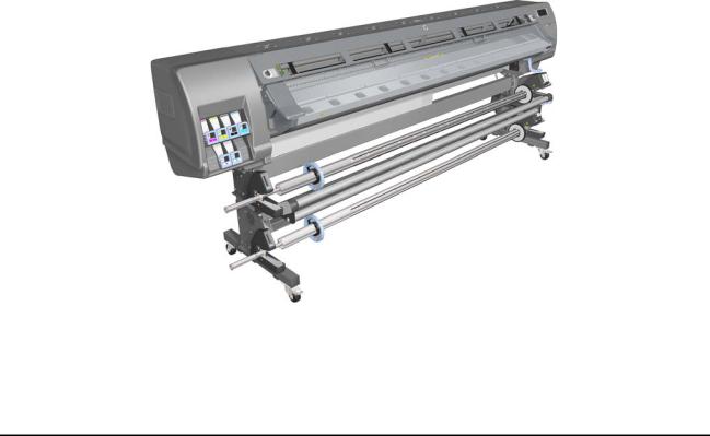
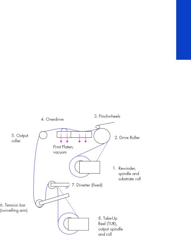
1.The substrate is loaded onto the Input Spindle (1), which is driven by the rewinder mechanism to provide back tension to the substrate. The substrate is fed through the Input Platen, around the Drive Roller (2), under the Pinchwheels (3), over the printzone and Overdrive (4), and finally it is either left free or looped through the Tension Bar (6) and the Diverter (7) to be collected on the Take-Up Reel (8).
2.The Rewinder has a motor that primarily acts as a brake to maintain tension on the substrate. The Rewinder may turn in either direction, depending on which is the printable side of the input substrate roll and its winding direction.
3.The Drive Roller also has a motor, and is the primary component that advances the substrate. The substrate is pressed to the drive roller by the pinchwheels, ensuring a smooth substrate advance. The motor receives feedback from an encoder located at the left side of the roller, inside a protected enclosure on the left of the left sideplate.
4.The surface of the substrate path where the substrate is printed is called the Print Platen. The Print Platen is designed to give minimal resistance to the substrate advance, and includes suction holes that apply vacuum to the substrate.
Printer systems
Printer systems |
23 |

Printer systems
5.The printer detects and controls the substrate advance. The OMAS sensor, located on a special cut-out section of the Print Platen, is a sensor that is able to detect very small errors in the advance of the substrate. These errors are communicated to the motors on the Drive Roller, and small correctional adjustments are applied to the movement of the substrate.
In the same area, but not visible from outside the printer, is the TOMAS sensor that measures the temperature in the area and helps OMAS to provide the drive motors with a high degree of accuracy.
NOTE: The OMAS sensor cannot see the fibers on some substrates, such as transparent substrate or very dark or very reflective substrates. In these cases, the OMAS sensor can be disabled. To disable the OMAS sensor See page 176.
6.The vacuum is calibrated according to the substrate type and print options used. It draws the substrate to the Print Platen, making sure that the substrate is flat. The substrate is also under the dryer when it is in the print zone.
7.The area of the platen in front of the print zone holds the Overdrive wheels. This area also has vacuum to ensure traction over the wheels, which are connected to the Drive Roller through a set of gears. The Overdrive wheels help to remove the substrate from the print zone during substrate advance.
8.After the platen, the substrate goes through the curing zone and finally leaves the printer, either to be collected on the Take-Up Reel or to be cut.
9.When the Take-Up Reel is in use, the substrate must be threaded first under the swiveling Tension Bar and rerouted to the output roll around the fixed Diverter roller. This system creates tension on the outgoing substrate for proper winding. The Take-Up Reel can operate in both directions with the Rewinder, winding with the printed face outside or inside. Weights on the Tension Bar arms may be slid forward in order to create higher tension for textile substrates.
Startup, substrate load, substrate selection
During startup, the printer checks that the substrate path components are functioning correctly. When shutting down, if a substrate is loaded, the printer remembers the substrate definition. This may be modified through the front panel with the option ’Change loaded substrate’ from the substrate menu list.
During substrate loading the printer may ask the user two interactions:
1.To rewind manually the substrate: The printer automatically checks the direction of the loaded substrate (printed face outwards or printed face inwards). If the ’curve’ of substrate is too large the printer cannot detect it and the printer asks the user to rewind manually. Once the substrate is rewound the printer can detect automatically
2.To align the substrate in order to avoid skew: the printer measures skew. If the skew is too large the printer will ask the user to lift the pinchwheels (big blue lever on right hand side) and align the substrate. The substrate must be aligned against itself (substrate edge must be aligned with input roll edge).
24 |
Printer systems |
Components
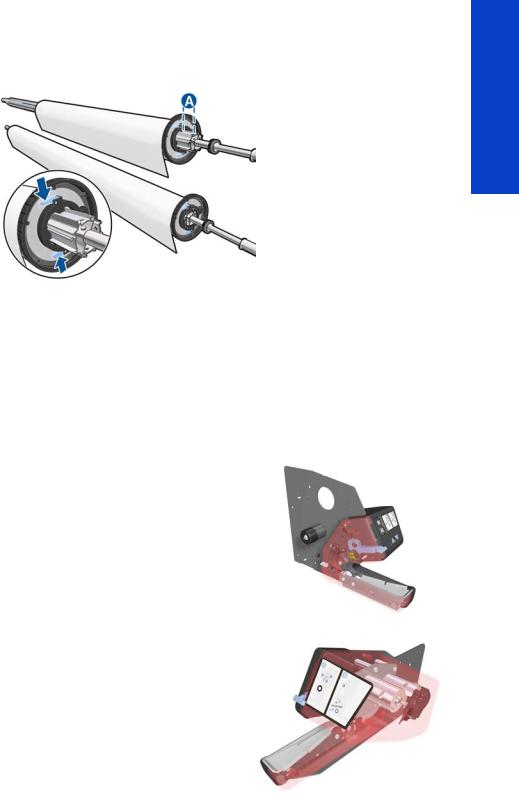
Spindle
Printer systems
The spindle can load 3” core rolls. It holds the core of the roll when its rubber bands are nipped between the core of the roll and the aluminum extrusion.
The hub on the left side has two possible fixed positions: the end position allows loading maximum width rolls, but there is a second position at 2.6 inches (65 mm) from the end that can be selected.
The right hub can be set along any length of the spindle so any length of roll can be loaded.
The right end of the spindle contains a gear which is used to transmit the movement from the rewinder to the roll.
Spindle latch
The spindle latch prevents the substrate roll from slipping from its position when printing. It is not necessary to close it when inserting the spindle, it closes automatically. But the user must lift the small blue lever in order to release the spindle and extract the roll of substrate.
Rewinder
The rewinder motor keeps a constant tension on the input substrate to prevent skew problems. There is a motor and a transmission that gives torque to the spindle in order to provide the necessary back tension.
Media sensor
The Input Platen has a lever that activates the media sensor whenever substrate is present. When the substrate is inserted into the entry area, the sensor is activated and the drive roller starts turning to help the loading process. The substrate load process has been triggered and the printer will provide instructions through the front panel.
Printer systems |
25 |
Printer systems
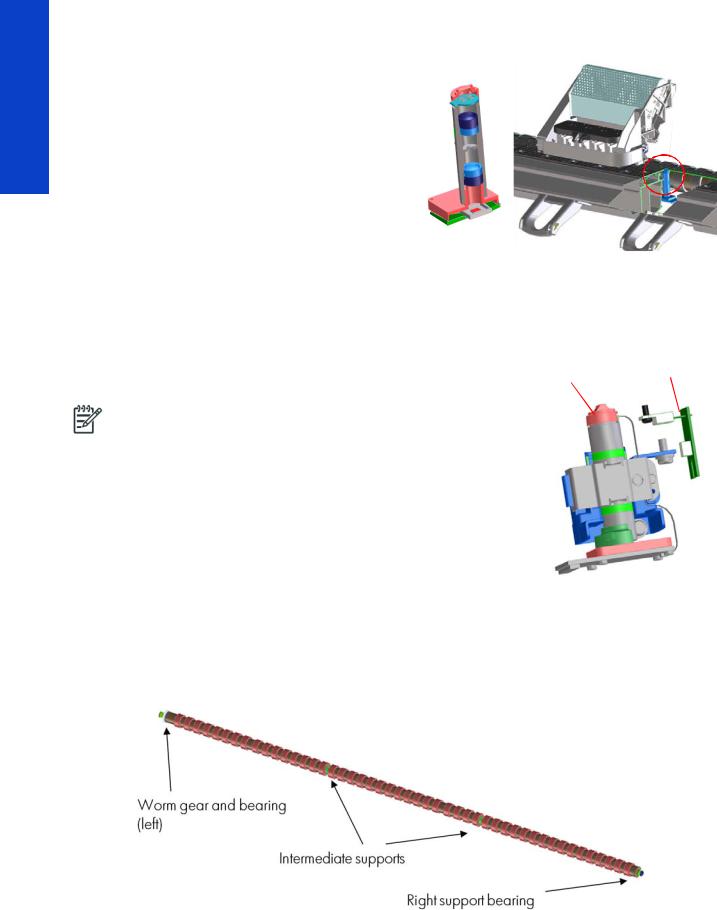
OMAS sensor (media advance sensor)
OMAS is located under the third platen slab from |
OMAS |
OMAS |
|
the right, only the top window can be seen: |
|||
|
location |
||
|
|
||
OMAS is composed of two parts: the sensor and |
|
|
|
its optics located under the platen and a PCI |
|
|
|
control board on the main electronics box. Both |
|
|
|
are connected through a ribbon cable that runs |
|
|
|
through the vacuum beam, by the right sideplate |
|
|
|
and into the electronics box. |
|
|
The optical sensor detects the surface of the back of the substrate as it moves across the platen. The
sensor is able to evaluate the exact movement of the substrate, and communicate any small
adjustments required by the system to move the substrate accurately.
The window of the OMAS sensor must be cleaned of dust and ink to work correctly. The cleaning procedure is described in the User’s Guide, in the section ‘Clean the substrate-advance sensor window’.
During the substrate load, the printer detects that the substrate has |
TOMAS sensor |
|
reached the print platen when the OMAS captures its image. |
||
OMAS sensor location |
||
|
||
NOTE: The OMAS sensor cannot detect the surface of some |
|
|
substrates, such as plastic or very dark ones. In these cases, the |
|
|
OMAS sensor must be disabled, and instead the printer uses |
|
|
feedback from the Driver Roller encoder to calculate the substrate |
|
|
advance. To disable the OMAS sensor, locate the OMAS Sensor |
|
|
selector from the print options menu of the RIP and set it to OFF. This |
|
|
can also be done from the Service menu page 176. |
|
|
|
|
TOMAS
To compensate for temperature changes and mechanical expansion,
OMAS receives a temperature reading from TOMAS sensor.
Drive roller and motor
The drive roller and motor advance the substrate through the substrate path. The motor requires 42 V, and is controlled by the Printmech PCA.
The drive roller receives the torque from the motor through a worm as in the Z6100 and other Designjets. Because of the extension to 104 inches, the roller now has two intermediate supports.
Drive Roller Encoder Disc and Encoder PCA
The Drive Roller Encoder Disc and Encoder PCA provide the feedback system for the Drive Roller.
26 |
Printer systems |
•The Encoder disc is a round disc mounted to the left end of the Drive Roller.
•The Encoder PCA is mounted with a sensor that reads the encoder movements of the disc (the disc turns with the drive roller).
Pinchwheels
The pinchwheels press the substrate against the Drive Roller to make sure that the Drive Roller can advance the substrate correctly.
•The pinchwheels are activated with the blue lever at the right side of the substrate roll and usually do not have to be lifted unless to correct skew during substrate load or to clear jams.
•The pinchwheel system has a sensor that detects if the system is up or down.
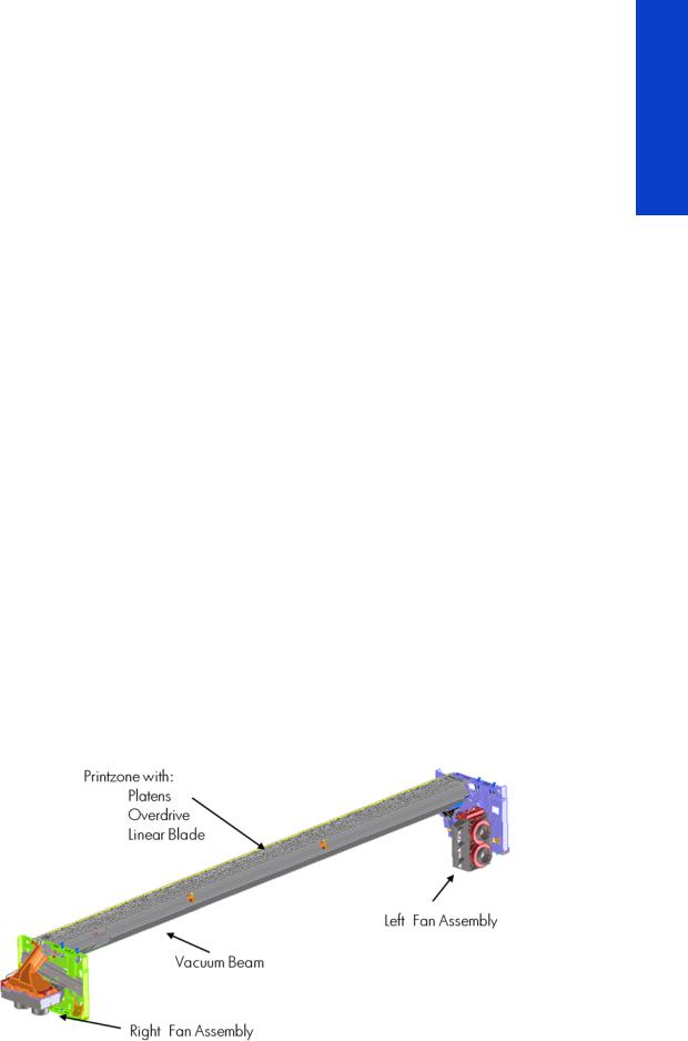
Vacuum Pump, Vacuum Tube Assembly, Vacuum Beam
The print zone is the area of the substrate path where the transmission of ink to the substrate occurs. The main function of the system can be defined as providing the surface where the substrate is printed, keeping it controlled during the process, playing a main roll on the final IQ of the plots and on the operational reliability of the printer. The subsystem is composed of the print platen assembly (including the overdrive wheels), which is the physical interface with the substrate, and the vacuum system which is the mechanical system where the vacuum pressure used to control the substrate is generated and conduced.
The HP Designjet L28500 printer requires a hot print zone (with additional airflow) to allow the evaporation of the majority of the water in the latex inks. This feature, plus the new substrates supported, changes a little the main contributors of the cockle control and substrate expansion from former products and also adds new issues such as the thermal marks. The platen gives a convenient shape to the heated substrate, avoiding differential temperatures due to platen conductivity.
The main components are:
•OVD & Platen Assembly 104” including:
•12 DJ L26500 printer platen + 1 OMAS platen + 2 interplaten 60 + 1 platen right end + 1 platen left end
•Linear blade 104” + springs (same as DJ Z6100 or L26500)
•OVD shafts and wheels (same as DJ Z6100, with some new segments)
•Foams, foam fillings, and foam wall
•Magnets under the platen to hold Media Edge Holders
•ESD brushes
•OVD gears in brass
•Right Vacuum Fan Assembly with Eola Control Board (same as DJ Z6200 or T7100)
•Left Vacuum Fan Assembly with Eola Control Board (new)
Printer systems
Printer systems |
27 |

Printer systems
Related tests, utilities, and calibrations
•Rewinder test page 148
•Drive Roller test page 149
•Substrate Path sensor test page 150
•Vacuum Test
•OMAS Test page 152
•Rewinder Motor polarity test
•Substrate path menu page 176
•Substrate advance adjustment page 184
Service parts
•Drive Roller page 257.
•Media Path Assemblies page 258.
•Center guide Pinchwheels Assemblies page 259.
•Media Entry Assemblies page 260.
•Take-up reel Assemblies page 261.
Removal and installation
•Rewinder page 341.
•Vacuum Fan page 346.
•OMAS page 422.
•TOMAS page 428.
•Output Platen page 514.
•Print Platen page 520.
•Input Roller page 532.
•Output Roller page 544.
•Media Sensor page 547.
•Pinchwheel Assembly page 554.
•Center Guide page 560.
•Driver Roller page 560.
•Rollfeed Modules page 567.
•Take-up reel page 567.
28 |
Printer systems |
Ink Delivery System (IDS)
Ink Delivery System
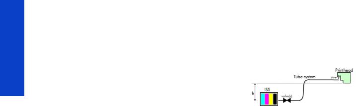
The ink deliver system (IDS) is located in the left enclosure of the printer (inside the left covers) and delivers a continuous supply of ink to the printheads. It can detect an ink leakage anywhere in the system, including inside an Ink Cartridge. It also tracks and determines when an Ink cartridge needs replacing.
Insulation
Ink Tubes Carrier
Top ISS: M, Y, K, C
Lower ISS: Lm, Lc
Rear of the Ink Supply Station
Ink tubes
Air tubes
On top of the ISS there is a thin plastic sleeve to avoid the substrate falling into the Ink Supply Station when a substrate crash occurs and also to avoid the direct heat radiation from the dryer
non-return valves  for the lower ISS
Spring loaded
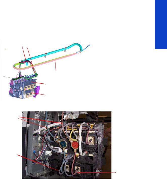
Ink Tubes
There are 6 ink tubes that deliver the inks to the printheads in the carriage and two additional tubes which are used as a support structure. They are bundled together in a carrier and held on a shelf on the inside of the top cover with clips.
Insulation Sleeve
The ink tubes are protected from the high temperatures of the Dryer Assembly by a heat resistant insulation sleeve, which protects the main body of the tubes, that are static.
Upper and Lower Ink Supply Station (ISS)
The Ink Supply Station (ISS) is divided into the upper and lower sections. They have six slots for holding the ink cartridges. Each slot has a unique shape (or lock out) which matches with an equal shape at the end of the applicable ink cartridge. this arrangement avoids the incorrect insertion of an ink cartridge, which would cause major damage to the ink system.
Printer systems
Printer systems |
29 |
Printer systems
There are two places for additional slots but these are covered over.
The upper and lower ISS both contain PCAs, although the top PCA contains more functionality, such as the pressure sensor, see page 13.
Non-return valves
The two non-return valves are only for the inks on the lower IDS. This is to ensure that when the pump stops and the cartridges are nearly empty, that the ink does not flow back to the cartridge.
If a cartridge is nearly empty, with no pressure from the pump, the cartridge bag might increase, and air might enter the printhead.
With a valve, the ink can go only from the cartridge to the printhead, and not the reverse!
Air Pressure System (APS)
The APS contains two air pumps which are used to force the ink through the tubes to the carriage assembly. In the event of a broken bag in one of the Ink Cartridges, these tubes must be checked in case any of the leaked ink has been forced into the air tubes.
Related tests, utilities, and calibrations
•Ink Delivery System tests: page 153.
Service parts
•Left hand assembly: page 249
Removal and installation
•Ink supply tubes and trailing cable: page 371
•ISS to Cartridge Cables: page 381
•Ink Supply Station: page 384
•Ink Supply Station PCAs: page 388
•APS Assembly: page 392.
•APS Assembly: page 392.
30 |
Printer systems |
Loading...