


 Loading...
Brocade 8Gb SAN Switch for HP BladeSystem c-Class User Guide
Abstract
This document provides information about setting up, configuring, and maintaining the Brocade 8Gb SAN Switch for HP BladeSystem c-Class. It is intended for system administrators and technicians with knowledge of SANs BladeSystems.
HP Part Number: 5697-3044
Published: December 2013
Edition: 3
©Copyright 2008, 2013 Hewlett-Packard Development Company, L.P.
©Copyright 2008, 2013 Brocade Communications Systems, Incorporated
The information contained herein is subject to change without notice. The only warranties for HP products and services are set forth in the express warranty statements accompanying such products and services. Nothing herein should be construed as constituting an additional warranty. HP shall not be liable for technical or editorial errors or omissions contained herein.
WARRANTY STATEMENT: To obtain a copy of the warranty for this product, see the warranty information website:
http://www.hp.com/go/storagewarranty
Acknowledgements
Microsoft® and Windows® are U.S. registered trademarks of Microsoft Corporation.
UNIX® is a registered trademark of The Open Group.

Contents |
|
1 Overview.................................................................................................. |
6 |
8Gb SAN Switch features.......................................................................................................... |
6 |
Component identification...................................................................................................... |
6 |
Port side of the 8Gb SAN Switch....................................................................................... |
7 |
Internal ports summary......................................................................................................... |
7 |
8Gb SAN Switch redundancy............................................................................................... |
8 |
8Gb SAN Switch licensing.................................................................................................... |
8 |
ISL trunking groups .................................................................................................................. |
8 |
Supported optional software...................................................................................................... |
8 |
Additional software features in HP BladeSystem c-Class Power Pack+ models.................................... |
9 |
Supported SFP transceiver options.............................................................................................. |
9 |
2 Setup...................................................................................................... |
10 |
Installation and safety considerations........................................................................................ |
10 |
Installing multiple switches................................................................................................... |
10 |
Electrical considerations...................................................................................................... |
11 |
Environmental considerations............................................................................................... |
11 |
Install the 8Gb SAN Switch...................................................................................................... |
11 |
OA power verification........................................................................................................ |
13 |
Check LEDs....................................................................................................................... |
13 |
Set the switch Ethernet IP address.............................................................................................. |
13 |
Using Enclosure Bay IP Addressing (EBIPA)............................................................................ |
14 |
Using external DHCP.......................................................................................................... |
14 |
Setting the IP address manually............................................................................................ |
14 |
Configure the 8Gb SAN Switch................................................................................................ |
15 |
Items required for configuration............................................................................................ |
15 |
Connect to the Command Line Interface................................................................................ |
15 |
Setting the date and time.................................................................................................... |
16 |
Verifying installed licenses................................................................................................... |
16 |
Modifying the FC domain ID (optional)................................................................................. |
16 |
Disabling and enabling a switch.......................................................................................... |
17 |
Disabling and enabling a port............................................................................................. |
17 |
Using Dynamic Ports On Demand (DPOD)............................................................................. |
18 |
DPOD commands.............................................................................................................. |
18 |
Verifying the configuration.................................................................................................. |
19 |
Backing up the configuration............................................................................................... |
19 |
3 Managing the 8Gb SAN Switch................................................................. |
20 |
Maintaining the 8Gb SAN Switch............................................................................................. |
20 |
Installing dust covers in empty ports...................................................................................... |
20 |
Replacing an SFP transceiver............................................................................................... |
20 |
Diagnostic tests.................................................................................................................. |
21 |
Powering on and off................................................................................................................ |
22 |
Interpreting LED activity........................................................................................................... |
22 |
LED indicators................................................................................................................... |
22 |
LED patterns........................................................................................................................... |
22 |
Module status LED patterns.................................................................................................. |
22 |
Port link status LED patterns................................................................................................. |
23 |
POST and boot specifications................................................................................................... |
23 |
POST................................................................................................................................ |
24 |
Boot................................................................................................................................. |
24 |
Interpreting POST results..................................................................................................... |
24 |
Contents 3
Firmware update.................................................................................................................... |
24 |
About the Reset button............................................................................................................. |
25 |
Rebooting the switch.......................................................................................................... |
25 |
Replacing a faulty 8Gb SAN Switch.......................................................................................... |
25 |
4 Support and other resources...................................................................... |
27 |
HP technical support............................................................................................................... |
27 |
Subscription service............................................................................................................ |
27 |
Documentation feedback.................................................................................................... |
27 |
Related information................................................................................................................. |
27 |
HP websites...................................................................................................................... |
27 |
Rack stability..................................................................................................................... |
28 |
Typographic conventions......................................................................................................... |
28 |
Customer self repair................................................................................................................ |
29 |
A SAN Switch technical specifications............................................................ |
30 |
Weight and physical dimensions.............................................................................................. |
30 |
Environmental requirements...................................................................................................... |
31 |
Supported SFPs...................................................................................................................... |
31 |
Supported HBAs..................................................................................................................... |
31 |
B Regulatory compliance notices................................................................... |
32 |
Regulatory compliance identification numbers............................................................................ |
32 |
Federal Communications Commission notice.............................................................................. |
32 |
FCC rating label................................................................................................................ |
32 |
Class A equipment........................................................................................................ |
32 |
Class B equipment........................................................................................................ |
32 |
Declaration of Conformity for products marked with the FCC logo, United States only................. |
33 |
Modification..................................................................................................................... |
33 |
Cables............................................................................................................................. |
33 |
Canadian notice (Avis Canadien)............................................................................................. |
33 |
Class A equipment............................................................................................................. |
33 |
Class B equipment............................................................................................................. |
33 |
European Union notice............................................................................................................ |
33 |
Japanese notices.................................................................................................................... |
34 |
Japanese VCCI-A notice...................................................................................................... |
34 |
Japanese VCCI-B notice...................................................................................................... |
34 |
Japanese VCCI marking..................................................................................................... |
34 |
Japanese power cord statement........................................................................................... |
34 |
Korean notices....................................................................................................................... |
35 |
Class A equipment............................................................................................................. |
35 |
Class B equipment............................................................................................................. |
35 |
Taiwanese notices................................................................................................................... |
35 |
BSMI Class A notice........................................................................................................... |
35 |
Taiwan battery recycle statement.......................................................................................... |
35 |
Turkish recycling notice............................................................................................................ |
35 |
Vietnamese notice................................................................................................................... |
36 |
Laser compliance notices......................................................................................................... |
36 |
English laser notice............................................................................................................ |
36 |
Dutch laser notice.............................................................................................................. |
36 |
French laser notice............................................................................................................. |
37 |
German laser notice........................................................................................................... |
37 |
Italian laser notice.............................................................................................................. |
37 |
Japanese laser notice......................................................................................................... |
38 |
Spanish laser notice........................................................................................................... |
38 |
Recycling notices.................................................................................................................... |
38 |
4Contents
English recycling notice...................................................................................................... |
38 |
Bulgarian recycling notice................................................................................................... |
38 |
Czech recycling notice........................................................................................................ |
39 |
Danish recycling notice....................................................................................................... |
39 |
Dutch recycling notice......................................................................................................... |
39 |
Estonian recycling notice..................................................................................................... |
40 |
Finnish recycling notice....................................................................................................... |
40 |
French recycling notice....................................................................................................... |
40 |
German recycling notice..................................................................................................... |
40 |
Greek recycling notice........................................................................................................ |
41 |
Hungarian recycling notice................................................................................................. |
41 |
Italian recycling notice........................................................................................................ |
41 |
Latvian recycling notice....................................................................................................... |
41 |
Lithuanian recycling notice.................................................................................................. |
42 |
Polish recycling notice......................................................................................................... |
42 |
Portuguese recycling notice................................................................................................. |
42 |
Romanian recycling notice.................................................................................................. |
42 |
Slovak recycling notice....................................................................................................... |
43 |
Spanish recycling notice..................................................................................................... |
43 |
Swedish recycling notice..................................................................................................... |
43 |
Battery replacement notices..................................................................................................... |
43 |
Dutch battery notice........................................................................................................... |
43 |
French battery notice.......................................................................................................... |
44 |
German battery notice........................................................................................................ |
44 |
Italian battery notice.......................................................................................................... |
45 |
Japanese battery notice...................................................................................................... |
45 |
Spanish battery notice........................................................................................................ |
46 |
Safety guidelines.................................................................................................................... |
46 |
Electrostatic discharge recommendations............................................................................... |
46 |
Grounding methods........................................................................................................... |
46 |
Battery replacement notice.................................................................................................. |
47 |
Taiwan battery recycling notice............................................................................................ |
47 |
Power cords...................................................................................................................... |
47 |
Japanese power cord notice................................................................................................ |
48 |
C Environmental regulation compliance.......................................................... |
49 |
China RoHS........................................................................................................................... |
49 |
Environmental Protection Use Period (EPUP) Disclaimer............................................................ |
49 |
TS/HS Dual Language Sheet............................................................................................... |
49 |
Glossary.................................................................................................... |
52 |
Index......................................................................................................... |
58 |
Contents 5

1 Overview
The Brocade 8Gb SAN Switch for HP BladeSystem c-Class (referred to in the rest of this manual as the 8Gb SAN Switch) is a Fibre Channel (FC) switch that supports link speeds of up to 8 Gbps. The 8Gb SAN Switch can operate in a fabric containing multiple switches or as the only switch in a fabric.
NOTE: In this document, the Brocade 8Gb SAN Switch refers to those Brocade FC switch modules compatible with the HP BladeSystem c-Class enclosure only.
8Gb SAN Switch features
The 8Gb SAN Switch provides the following features:
•Fully integrated, embedded FC SAN design that connects directly to the HP BladeSystem c-Class enclosure midplane
•Dynamic Ports on Demand (DPOD), which automatically detects port connections, assigns port licenses, and enables ports
•Easy-to-manage HP Storage Essentials Systems Insight Manager support
•Full compatibility with HP StorageWorks B-series switches and Brocade fabrics
•Sixteen internal 1/2/4/8 Gbps auto-sensing Small Form-factor Pluggables (SFPs) with the following characteristics:
◦Independent automatic negotiation to the highest common speed for each server FC port connected to the switch
◦Universal self-configuring ports, which are capable of becoming F_Ports (fabric enabled)
•Eight external 1/2/4/8 Gbps FC SFP ports, with the following characteristics:
◦Automatic negotiation to the highest common speed of all devices connected to the port
◦Port-interface-compatible SFP transceivers, both short-wavelength (SWL) and long wavelength (LWL)
◦Universal self-configuring ports, which are capable of becoming F_Ports, FL_Ports (fabric loop enabled), or E_Ports (expansion ports)
•Heterogeneous support for mixed storage fabrics
•Power supplied and controlled by the BladeSystem enclosure
•Identification to HP chassis management with HP specified SEEPROMs
•Hot-swap capability
•Compatibility with redundant and dual redundant switch configurations in c-Class BladeSystem
•Hot code activation
•Real-time clock
•SFP port monitoring
Component identification
Figure 1 (page 7) identifies the physical components of the 8Gb SAN Switch.
6Overview

Figure 1 Brocade 8Gb SAN Switch components
1. Midplane connector |
2. Eight external SFP ports |
|
3. |
Installation handle |
4. Unit ID (UID), Health, and Status LEDs |
5. |
Reset button |
|
Port side of the 8Gb SAN Switch
Figure 2 (page 7) identifies 8Gb SAN Switch external ports (ports 17 through 20, and ports 21 through 0).
Figure 2 8Gb SAN Switch external ports
1. Left bank—ports 17, 18, 19, 20 |
2.Right bank—ports 21, 22, 23, 0 |
NOTE: See “Interpreting LED activity” (page 22) for complete information on 8Gb SAN Switch LEDs.
Internal ports summary
Sixteen logical internal ports (numbered 1 through 16) connect sequentially to server bays 1 through 16 with the enclosure midplane. Server bay 1 is connected to Switch Port 1, Server bay 2 is connected to Switch port 2, and so forth.
8Gb SAN Switch features 7

8Gb SAN Switch redundancy
The HP BladeSystem c-Class was engineered as a no-single-point-of-failure bladed solution. Attributes that contribute to switch redundancy include:
•Redundant power and cooling
•Redundant HP Onboard Administrator (OA) to ensure management access to the switch
NOTE: The HP Onboard Administrator is the enclosure management module used to support and manage the HP BladeSystem c-Class and all managed devices used in the enclosure.
8Gb SAN Switch licensing
The 8Gb SAN Switch integrates one of three license options that complement existing HP product lines. Some 8Gb SAN Switch models ship with licenses that place limits on the number of domains that can be used. Models and their specific licenses are as follows:
•Brocade 8/12 SAN Switch for HP BladeSystem c-Class, base, integrating 12 active ports (in any combination of internal/external ports) and two short-wavelength SFPs. Software components include a Full Fabric license, the Advanced Web Tools GUI and Zoning software.
•Brocade 8/24 SAN Switch for HP BladeSystem c-Class, base, integrating 24 active ports (16 internal and 8 external) and four short-wavelength SFPs. Software components include a Full Fabric license, Advanced Web Tools GUI, and Zoning software.
•Brocade 8/24 Gb SAN Switch for HP BladeSystem c-Class, Power Pack, integrating 24 active ports (16 internal and 8 external) and four short-wavelength SFPs. Software components include a Full Fabric license, AdvancedWeb Tools GUI, and Zoning software plus these additional software features:
◦Fabric Watch
◦ISL Trunking
◦Advanced Performance Monitoring (APM)
◦Extended Fabric
IMPORTANT: Upgrade the 8Gb SAN Switch by purchasing optional licenses; access the latest version of the HP StorageWorks Fabric OS Administrator Guide to learn how to add a license.
ISL trunking groups
If your 8Gb SAN Switch is licensed for interswitch link (ISL) trunking, use the trunking groups available on the switch.
The FC ports are numbered from left to right, and are part of the same ISL trunking group. The trunking group consists of the ports shown in Figure 2 (page 7).
NOTE: ISL trunking is optional software that allows you to create trunking groups of ISLs between adjacent switches. ISL trunking is available on the Brocade 8Gb SAN Switch for HP BladeSystem c-Class Power Pack+ model, or by purchasing the optional license described in “8Gb SAN Switch licensing” (page 8). For more information about trunking, see the latest version of the HP StorageWorks Fabric OS Administrator Guide.
Supported optional software
The following optional software kits can be activated by purchasing the corresponding license key:
•Fabric Watch
•Extended Fabrics
8Overview

•Advanced Performance Monitoring (APM)
•HP B-series 8-24 Port ISL Trunking LTU
•HP B-series 8-24 Pt Adaptive Network LTU
•HP B-series 8-24 Power Pack+ Upgrade
•Fabric Manager
•Brocade 8Gb and 16Gb SAN Switch for HP BladeSystem c-Class Fabric Vision LTU1
Additional software features in HP BladeSystem c-Class Power Pack+ models
The 8Gb SAN Switch for HP BladeSystem c-Class Power Pack+ includes the following optional software:
•ISL Trunking
•Fabric Watch
•Advanced Performance Monitoring
•Extended Fabrics
For information on any of these features, see the latest version of the HP StorageWorks Fabric OS Administrator Guide.
Supported SFP transceiver options
Optional Long Wave 4Gb SFPs:
•HP 4Gb Long Wave B-series FC SFP 1 Pack - 10 km
•HP 4Gb Long Wave B-series FC SFP 1 Pack - 30 km
Table 1 HP 8Gb Short Wave B-series FC SFP+ 1 Pack
Distance |
OM2 Cable |
OM3 Cable |
8Gb performance |
50 meters |
150 meters |
4Gb performance |
150 meters |
270 meters |
2Gb performance |
300 meters |
500 meters |
1Gb performance |
500 meters |
860 meters |
Table 2 HP 4Gb Short Wave B-series FC SFP 1 Pack
Distance |
OM2 Cable |
OM3 Cable |
4Gb performance |
150 meters |
270 meters |
2Gb performance |
300 meters |
500 meters |
1Gb performance |
500 meters |
860 meters |
1. Fabric OS 7.2.0a or later
Additional software features in HP BladeSystem c-Class Power Pack+ models |
9 |
2 Setup
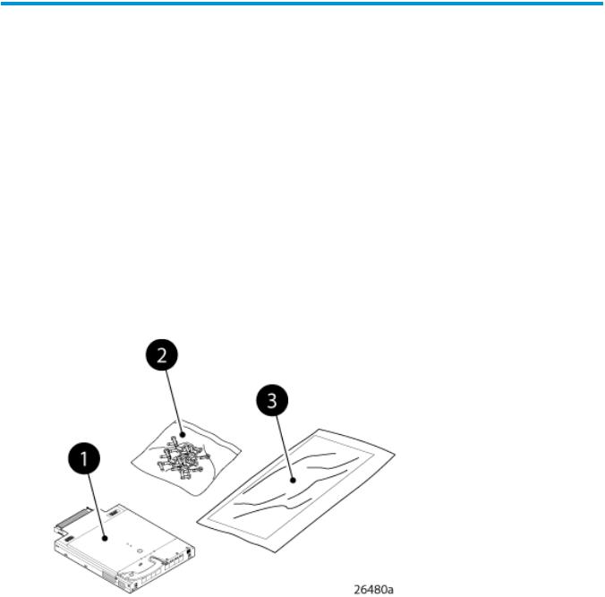
Shipping carton contents
Figure 3 (page 10) identifies the 8Gb SAN Switch shipping carton contents:
•Brocade 8Gb SAN Switch for HP BladeSystem c-Class installation instructions
•SFP dust covers (must be inserted in ports where Small Form-factor Pluggable (SFP) optical transceivers are not installed)
•Four Short Wavelengh (SWL) 8Gb SFPs (in styrofoam packing)
•One Brocade 8Gb SAN Switch; models include:
◦Brocade 8/12 SAN Switch for HP BladeSystem c-Class with twelve active ports
◦Brocade 8/24 SAN Switch for HP BladeSystem c-Class with sixteen internal and eight external active ports
◦Brocade 8/24 SAN Switch Power Pack+ for HP BladeSystem c-Class with sixteen internal and eight external active ports
Figure 3 Carton contents
1. Brocade 8Gb SAN Switch, ships with four Short |
2. Dust covers for empty SFP ports |
Wavelengh (SWL) 8Gb SFPs, (in styrofoam packing) |
|
3. Brocade 8Gb SAN Switch for HP BladeSystem c-Class installation instructions
Installation and safety considerations
The 8Gb SAN Switch installs in the I/O bays in the rear of the HP BladeSystem c-Class enclosure. See the appropriate BladeSystem Enclosure Setup and Installation Guide for specific enclosure requirements.
Installing multiple switches
If you do not have a DHCP server connected to the OA, install and configure one 8Gb SAN Switch at a time. This is required so that Ethernet IP address conflicts do not occur with duplicate default Ethernet IP addresses.
10 Setup
IMPORTANT: DHCP is enabled by default on this switch. In cases where DHCP is available, IP address conflicts will not occur, simplifying multiple switch installations. See “Using external DHCP” (page 14).
Each switch must be assigned a unique Ethernet IP address during configuration. Once the default Ethernet IP address on the 8Gb SAN Switch has been changed, you may install additional 8Gb SAN Switches in the enclosure.
See the appropriate HP BladeSystem Enclosure Setup and Installation Guide for help identifying your specific enclosure setup, available connections, and power requirements.
Electrical considerations
The 8Gb SAN Switch requires 35 watts, provided by the enclosure. No other power requirement or provision exists.
Environmental considerations
Ensure proper cooling and ventilation by verifying the following:
•The air vents on the enclosure are not blocked or restricted.
•The ambient air temperature at the front of the enclosure does not exceed 35°C (95°F) while the switch is operating.
IMPORTANT: The dust covers that ship with your 8Gb SAN Switch must be inserted into any ports where SFPs are not installed, to help contain air flow in the BladeSystem chassis.
Install the 8Gb SAN Switch
Install the Brocade 8Gb SAN Switch into the enclosure:
1.Locate the appropriate interconnect bay in the rear of the enclosure as specified in the appropriate HP BladeSystem Enclosure Setup and Installation Guide provided with your enclosure.
IMPORTANT: Populate all enclosure I/O bays with the appropriate component (for example, a switch, Pass-Thru, or one of the blank panels provided with the enclosure).
2.Remove the slot cover (if installed).
CAUTION: Properly ground yourself before handling the switch.
3.Press the handle latch to release the installation handle. See Figure 4 (page 12).
Install the 8Gb SAN Switch 11

Figure 4 Releasing the installation handle
1. Installation handle in latched position |
2. Handle latch |
3. Installation handle (released)
NOTE: The Brocade 8Gb SAN Switch is a hot-pluggable device. The enclosure power may be on or off during installation.
4.Align the Brocade 8Gb SAN Switch with the appropriate interconnect bay according to your enclosure’s specific configuration. Push the switch firmly into the interconnect bay. See Figure 5 (page 12).
Figure 5 Installing the Brocade 8Gb SAN Switch into an interconnect bay
12 Setup
5.Press the installation handle into the latch to lock the Brocade 8Gb SAN Switch in place.
CAUTION: For proper cooling and EMI emissions control, all panels and doors should be in place and securely fastened while the unit is in operation.
OA power verification
The HP BladeSystem Onboard Administrator (OA) is the enclosure management processor that manages the devices contained within the enclosure. The OA provides a single point from which to perform basic management tasks on switches or server blades installed in the enclosure.
IMPORTANT: HP recommends reading the appropriate HP BladeSystem Enclosure User Guide and the HP BladeSystem Onboard Administrator User Guide. Reading these guides in sequence promotes an overall understanding of your specific enclosure model.
Once the switch is installed in the interconnect bay, the OA verifies that the switch type matches the mezzanine cards present on the servers. If there is no mismatch, the OA powers up the switch.
If the switch does not power up, check the enclosure and switch status with the OA web interface. See HP BladeSystem Onboard Administrator User Guide.
Check LEDs
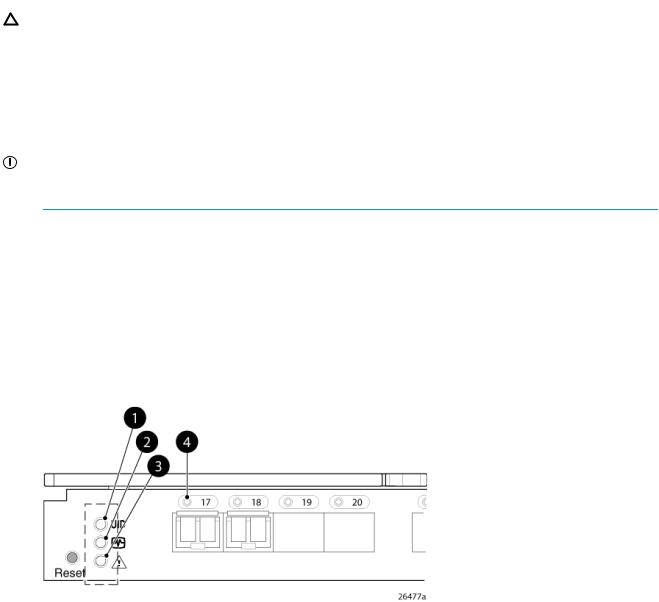
See Figure 6 (page 13) to locate power-on LEDs. Verify that the LEDs match the indicators described below the figure
Figure 6 Verifying power-on LEDs
1. UID LED |
Off |
2. Health ID LED |
Steady green light |
3. Module status LED |
Steady green light |
4. Port status LED |
Steady green light |
Set the switch Ethernet IP address
To set the Ethernet IP address:
1.Verify that the enclosure is powered on.
2.Verify that the switch is installed.
3.Choose one of the following methods to set the Ethernet IP address:
•Using Enclosure Bay IP Addressing (EBIPA)
•“Using external DHCP” (page 14)
•“Setting the IP address manually” (page 14)
Set the switch Ethernet IP address |
13 |

Using Enclosure Bay IP Addressing (EBIPA)
To set the Ethernet IP address using EBIPA:
1.Open a web browser and connect to the active OA.
2.Enable EBIPA for the corresponding interconnect bay.
3.Click Apply to restart the switch.
4.Verify the IP address using a Telnet or SSH login to the switch, or by selecting the switch in the OA GUI Rack Overview window.
NOTE: See the HP BladeSystem Onboard Administrator User Guide for additional information on EBIPA.
Using external DHCP
To set the Ethernet IP address using external DHCP:
1.Connect to the active OA with a web browser.
2.Document the DHCP-assigned address by selecting the switch from the OA GUI Rack Overview.
3.Verify the IP address using a Telnet or SSH login to the switch, or select the switch in the OA
GUI Rack Overview window.
Setting the IP address manually
To set the IP address manually:
NOTE: As an alternate method to using a null modem cable, use Telnet or SSH to access the IP address of the Onboard Administrator, resuming at Step 9.
1.Obtain the following items to set the IP address with a serial connection:
•Computer with a terminal application (such as HyperTerminal in a Windows environment or TERM in a UNIX environment)
•Null modem serial cable
2.Replace the default IP address (if present) and related information with the information provided by your network administrator. By default, the IP address is set to 10.77.77.77 for switches with revision levels earlier than 0C.
3.Verify that the enclosure is powered on.
4.Identify the active OA in the BladeSystem.
5.Connect a null modem serial cable from your computer to the serial port of the active OA.
6.Configure the terminal application as follows: In a Windows environment, enter:
•Bits per second—9600
•Databits—8
•Parity—None
•Stop bits—1
•Flow control—None
In a UNIX environment, enter tip /dev/ttyb –9600
7.Log in to the OA.
8.Press Enter to display the switch console.
14 Setup

9.Identify the interconnect bay number where the switch is installed. At the OA command line, enter:
connect interconnect x, where x is the interconnect bay slot where the switch is installed:
•User: admin
•Password: password
Enter entries as shown; commands are case sensitive.
10.Or follow the onscreen prompts to change your password now.
11.The OA will connect its serial line to the Switch in the specified interconnect bay. A prompt displays, indicating that the escape character for returning to the OA is Ctrl __ (underscore).
12.At the command line, enter: ipaddrset.
13.Enter the remaining IP addressing information as prompted.
14.Optionally, enter ipaddrshow at the command prompt to verify that the IP address is set correctly.
15.Record the IP addressing information, and store it in a safe place.
16.Enter Exit, and then press Enter to log out of the serial console.
17.Disconnect the serial cable. For additional assistance with operating the Onboard Administrator CLI, see the Onboard Administrator Command Line Interface User Guide for your specific enclosure, available at http://www.hp.com.
Configure the 8Gb SAN Switch
The 8Gb SAN Switch must be configured to ensure correct operation within a network and fabric. For instructions about configuring the switch to operate in a fabric containing switches from other vendors, see the HP SAN Design Reference Guide:
http://h18000.www1.hp.com/products/storageworks/san/documentation.html
For more information about the CLI, see the latest version of the Fabric OS command reference.
Items required for configuration
The following items are required for configuring and connecting the 8Gb SAN Switch for use in a network and fabric:
•8Gb SAN Switch installed in the enclosure
•IP address and corresponding subnet mask and gateway address recorded during the “Setting the IP address manually” (page 14) procedure
•Ethernet cable
•SFP transceivers and compatible optical cables, as required
•Access to an FTP server for backing up the switch configuration (optional)
Connect to the Command Line Interface
Make an Ethernet connection and log in to the 8Gb SAN Switch:
1.Connect the workstation to the Ethernet network containing the OA. If the OA is not on a network, connect directly to the OA/iLO Ethernet port on the active OA.
IMPORTANT: Verify that the switch is not being reconfigured from any other connections during the remaining steps.
2.Open a Telnet connection using the IP address set earlier. The login prompt displays when the Telnet connection locates the switch in the network.
3.Enter the user name, using the administrative account admin.
4.Enter the password. The default password is password.
Configure the 8Gb SAN Switch 15

NOTE: You can run up to two simultaneous admin sessions and four user sessions.
If you have not changed the system passwords from the default, you are prompted to change them. Enter the new system passwords, or press CTRL+c to skip the password prompts.
5.Verify that the login is successful. If successful, the prompt displays the switch name and user ID to which you are connected.
Setting the date and time
The date and time are used for logging events. 8Gb SAN Switch operation does not depend on the date and time; a switch with an incorrect date and time value functions properly.
To set the date and time using the CLI:
1.If you have not already done so, connect to the switch and log in as admin as described in “Connect to the Command Line Interface” (page 15).
2.Issue the date command using the following syntax: date mmddHHMMyy, where
•mm is the month; valid values are 01 through 12
•dd is the date; valid values are 01 through 31
•HH is the hour; valid values are 00 through 23
•MM is minutes; valid values are 00 through 59
•yy is the year; valid values are 00 through 99 (values greater than 69 are interpreted as 1970–1999, and values less than 70 are interpreted as 2000–2069).
For example:
switch:admin> date
Fri Jan 29 17:01:48 UTC 2000 switch:admin> date 0227123003 Thu Feb 27 12:30:00 UTC 2003 switch:admin>
For details about changing time zones, see the tsTimeZone command in the latest version of the Fabric OS Command Reference Guide.
Verifying installed licenses
To determine the type of licensing included with your 8Gb SAN Switch, enter licenseshow at the command prompt, as in the following example:
switch:admin> licenseshow XXXnnXXnXnnXXX:
Fabric Watch license Release v5.0 license XXXnnXXnXnnXXX:
Zoning license XXXnnXXnXnnXXX: Web license XXXnnXXnXnnXXX: Full Fabric
NOTE: For more information about the CLI, see the latest version of the Fabric OS Command Reference Guide.
Modifying the FC domain ID (optional)
If desired, you can modify the FC domain ID. The default FC domain ID is domain 1. If the 8Gb SAN Switch is not powered on until after it is connected to the fabric, and the default FC domain
16 Setup
ID is already in use, the domain ID for the new switch is automatically reset to a unique value. If the switch is connected to the fabric after is has been powered on and the default domain ID is already in use, the fabric segments.
Enter fabricshow to determine the domain IDs that are currently in use. The maximum number of domains with which the 8Gb SAN Switch communicates is determined by this switch's fabric license.
To modify the domain ID:
1.Enter switchdisable to disable the switch.
2.Enter configure, and then enter a new value or press Enter to accept each default value.
3.At the Fabric parameters prompt, enter Y and press Enter:
Fabric parameters (yes, y, no, n): [no] y
4.Enter a unique domain ID. For example:
Domain: (1..239) [1] 3
5.Complete the remaining prompts, or press Ctrl+D to accept the remaining default settings.
6.Enter switchenable to re-enable the switch.
7.Enter fabricshow to confirm any changes made to the domain ID.
8.Optionally, verify switch policy settings and specify any custom status policies that need to change:
a.Enter switchstatuspolicyshow to verify the current policy settings. If desired, enter switchstatuspolicyset at the prompt to change switch policy settings. This command sets the policy parameters that determine the overall switch status.
b.Customize the status policies as desired.
9.To deactivate the alarm for a particular condition, enter 0 at the prompt for that condition.
Disabling and enabling a switch
By default, the switch is enabled after power on and after the diagnostics and switch initialization routines complete. You can disable and re-enable the switch as necessary.
To disable:
1.If you have not already done so, connect to the switch, and log in as admin, as described in “Connect to the Command Line Interface” (page 15).
2.Issue the switchDisable command.
All Fibre Channel ports on the switch are taken offline. If the switch was part of a fabric, the fabric reconfigures.
To enable:
1.If you have not already done so, connect to the switch and log in as admin as described in “Connect to the Command Line Interface” (page 15).
2.Issue the switchEnable command.
All Fibre Channel ports that pass the Power-on Self Test (POST) are enabled. If the switch has interswitch links (ISLs) to a fabric, it joins the fabric.
Disabling and enabling a port
To enable a port:
1.Connect to the switch and log in as admin as described in Connect to the “Connect to the Command Line Interface” (page 15).
2.Issue portenable portnumber, where portnumber is the port number of the port you want to enable.
To disable a port:
Configure the 8Gb SAN Switch 17

1.If you have not already done so, connect to the switch and log in as admin as described in “Connect to the Command Line Interface” (page 15).
2.Issue portdisable portnumber, where portnumber is the port number of the port you want to disable.
Using Dynamic Ports On Demand (DPOD)
DPOD functionality does not require a predefined assignment of ports. Port assignment is determined by the total number of ports in use, as well as the number of purchased ports.
In summary, the DPOD feature simplifies port management by:
•Automatically detecting HBA connected server ports or cabled ports
•Automatically enabling ports
•Automatically assigning port licenses
To initiate DPOD, use the licensePort command, as described in “Connect to the Command Line Interface” (page 15).
IMPORTANT: For the Brocade 8Gb SAN Switch, DPOD works only if the server blade is installed with an HBA present. A server blade that does not have a functioning HBA is not treated as an active link for the purpose of initial POD port assignment.
DPOD commands
Use the licensePort command to manage dynamic POD assignments with the following options:
•licensePort –reserve portnum reserves a future license assignment for a specific port, even if the port is currently offline.
•licensePort –release portnum removes a license from a port.
•portCfgPersistentDisable blocks a specific port from future assignments.
•licensePort -show displays an overview of the POD license status and port assignments.
The following are examples of the licensePort -show command for a Brocade 8/12 SAN Switch and a Brocade 8/24 SAN Switch:
Example 1 Example for Brocade 8/12 SAN Switch
swd77:admin> licenseport -show
24 ports are available in this switch No POD licenses are installed Dynamic POD method is in use
12 port assignments are provisioned for use in this switch: 12 port assignments are provisioned by the base switch license *6 port assignments added if the 1st POD license is installed *6 more assignments added if the 2nd POD license is installed 4 ports are assigned to installed licenses:
4 ports are assigned to the base switch license Ports assigned to the base switch license:
15, 16, 17, 18*
Ports assigned to the first POD license: None
Ports assigned to the second POD license: None
Ports not assigned to a license:
0, 1, 2, 3, 4, 5, 6, 7, 8, 9, 10, 11, 12, 13, 14, 19 20, 21, 22, 23
18 Setup
Loading...