


 Loading...
HP ProLiant BL660c Gen8 Server Blade
User Guide
Abstract
This document is for the person who installs, administers, and troubleshoots servers and storage systems. HP assumes you are qualified in the servicing of computer equipment and trained in recognizing hazards in products with hazardous energy levels.
Part Number: 689414-001
August 2012
Edition: 1
© Copyright 2012 Hewlett-Packard Development Company, L.P.
The information contained herein is subject to change without notice. The only warranties for HP products and services are set forth in the express warranty statements accompanying such products and services. Nothing herein should be construed as constituting an additional warranty. HP shall not be liable for technical or editorial errors or omissions contained herein.
Microsoft® and Windows® are U.S. registered trademarks of Microsoft Corporation.
Bluetooth® is a trademark owned by its proprietor and used by Hewlett-Packard Company under license.

Contents |
|
Component identification............................................................................................................... |
6 |
Front panel components ............................................................................................................................. |
6 |
Front panel LEDs and buttons ...................................................................................................................... |
6 |
Drive LED definitions .................................................................................................................................. |
7 |
System board components.......................................................................................................................... |
8 |
Mezzanine connector definitions ....................................................................................................... |
9 |
DIMM slot locations ......................................................................................................................... |
9 |
Tool locations ......................................................................................................................................... |
10 |
HP c-Class Blade SUV Cable..................................................................................................................... |
10 |
Operations................................................................................................................................. |
12 |
Power up the server blade ........................................................................................................................ |
12 |
Power down the server blade.................................................................................................................... |
12 |
Remove the server blade .......................................................................................................................... |
13 |
Remove the access panel.......................................................................................................................... |
14 |
Remove a drive....................................................................................................................................... |
14 |
Removing DIMM baffles ........................................................................................................................... |
14 |
Remove the center DIMM baffle....................................................................................................... |
14 |
Remove the left DIMM baffle ........................................................................................................... |
15 |
Remove the right DIMM baffle......................................................................................................... |
16 |
Remove the front panel/drive cage assembly.............................................................................................. |
16 |
Remove the FBWC capacitor pack ............................................................................................................ |
17 |
Setup......................................................................................................................................... |
19 |
Installing an HP BladeSystem c-Class enclosure ........................................................................................... |
19 |
Preparing the enclosure.................................................................................................................. |
19 |
Installing interconnect modules .................................................................................................................. |
22 |
Interconnect bay numbering and device mapping.............................................................................. |
23 |
Connecting to the network........................................................................................................................ |
24 |
Installing server blade options................................................................................................................... |
24 |
Installing a server blade ........................................................................................................................... |
24 |
Assembling a full height blank .................................................................................................................. |
25 |
Completing the configuration .................................................................................................................... |
26 |
Hardware options installation....................................................................................................... |
27 |
Introduction ............................................................................................................................................ |
27 |
Drive option ........................................................................................................................................... |
27 |
Processor option...................................................................................................................................... |
28 |
Memory options ...................................................................................................................................... |
32 |
HP SmartMemory .......................................................................................................................... |
33 |
Memory subsystem architecture ....................................................................................................... |
33 |
Single-, dual-, and quad-rank DIMMs ............................................................................................... |
34 |
DIMM identification ....................................................................................................................... |
35 |
Memory configurations................................................................................................................... |
35 |
General DIMM slot population guidelines ......................................................................................... |
37 |
Installing a DIMM.......................................................................................................................... |
38 |
FBWC capacitor pack options .................................................................................................................. |
39 |
Contents |
3 |
Mezzanine card option............................................................................................................................ |
40 |
HP Trusted Platform Module option ............................................................................................................ |
42 |
Installing the Trusted Platform Module board ..................................................................................... |
43 |
Retaining the recovery key/password .............................................................................................. |
44 |
Enabling the Trusted Platform Module............................................................................................... |
45 |
Cabling ..................................................................................................................................... |
46 |
Cabling resources ................................................................................................................................... |
46 |
FBWC capacitor pack cabling .................................................................................................................. |
46 |
Using the HP c-Class Blade SUV Cable ...................................................................................................... |
47 |
Connecting locally to a server blade with video and USB devices.................................................................. |
48 |
Accessing a server blade with local KVM ......................................................................................... |
48 |
Accessing local media devices ........................................................................................................ |
49 |
Software and configuration utilities ............................................................................................... |
50 |
Server mode ........................................................................................................................................... |
50 |
Server QuickSpecs .................................................................................................................................. |
50 |
HP iLO Management Engine..................................................................................................................... |
50 |
HP iLO ......................................................................................................................................... |
50 |
Intelligent Provisioning.................................................................................................................... |
52 |
HP Insight Remote Support software ................................................................................................. |
54 |
Scripting Toolkit ............................................................................................................................ |
54 |
HP Service Pack for ProLiant ..................................................................................................................... |
55 |
HP Smart Update Manager............................................................................................................. |
55 |
HP ROM-Based Setup Utility ..................................................................................................................... |
55 |
Using RBSU .................................................................................................................................. |
56 |
Auto-configuration process.............................................................................................................. |
56 |
Boot options ................................................................................................................................. |
57 |
Configuring AMP modes ................................................................................................................ |
57 |
Re-entering the server serial number and product ID ........................................................................... |
57 |
Utilities and features ................................................................................................................................ |
58 |
Array Configuration Utility .............................................................................................................. |
58 |
Option ROM Configuration for Arrays ............................................................................................. |
59 |
ROMPaq utility.............................................................................................................................. |
59 |
Automatic Server Recovery ............................................................................................................. |
59 |
USB support.................................................................................................................................. |
59 |
Redundant ROM support ................................................................................................................ |
60 |
Keeping the system current ....................................................................................................................... |
60 |
Drivers ......................................................................................................................................... |
60 |
Software and firmware................................................................................................................... |
61 |
Version control .............................................................................................................................. |
61 |
HP Operating Systems and Virtualization Software Support for ProLiant Servers..................................... |
61 |
Change control and proactive notification ........................................................................................ |
61 |
Troubleshooting .......................................................................................................................... |
62 |
Troubleshooting resources ........................................................................................................................ |
62 |
Battery replacement .................................................................................................................... |
63 |
Regulatory compliance notices ..................................................................................................... |
64 |
Regulatory compliance identification numbers ............................................................................................. |
64 |
Federal Communications Commission notice............................................................................................... |
64 |
FCC rating label............................................................................................................................ |
64 |
FCC Notice, Class A Equipment ...................................................................................................... |
64 |
FCC Notice, Class B Equipment ...................................................................................................... |
64 |
Contents |
4 |
Declaration of conformity for products marked with the FCC logo, United States only |
....................................... 65 |
Modifications.......................................................................................................................................... |
65 |
Cables................................................................................................................................................... |
65 |
Canadian notice (Avis Canadien).............................................................................................................. |
65 |
European Union regulatory notice ............................................................................................................. |
66 |
Disposal of waste equipment by users in private households in the European Union ......................................... |
66 |
Japanese notice ...................................................................................................................................... |
67 |
BSMI notice ............................................................................................................................................ |
67 |
Korean notice ......................................................................................................................................... |
67 |
Chinese notice ........................................................................................................................................ |
68 |
Vietnam compliance marking notice .......................................................................................................... |
68 |
Ukraine notice ........................................................................................................................................ |
68 |
Laser compliance .................................................................................................................................... |
68 |
Battery replacement notice........................................................................................................................ |
69 |
Taiwan battery recycling notice................................................................................................................. |
69 |
Acoustics statement for Germany (Geräuschemission) .................................................................................. |
69 |
Electrostatic discharge................................................................................................................. |
71 |
Preventing electrostatic discharge .............................................................................................................. |
71 |
Grounding methods to prevent electrostatic discharge.................................................................................. |
71 |
Specifications............................................................................................................................. |
72 |
Environmental specifications ..................................................................................................................... |
72 |
Server blade specifications ....................................................................................................................... |
72 |
Support and other resources ........................................................................................................ |
73 |
Before you contact HP.............................................................................................................................. |
73 |
HP contact information............................................................................................................................. |
73 |
Customer Self Repair ............................................................................................................................... |
73 |
Acronyms and abbreviations........................................................................................................ |
81 |
Documentation feedback ............................................................................................................. |
83 |
Index......................................................................................................................................... |
84 |
Contents 5
Component identification
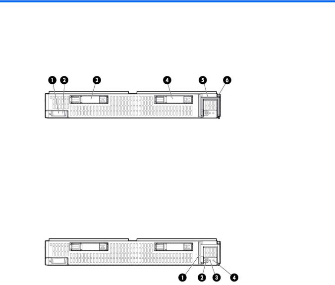
Front panel components
Item |
Description |
|
|
1 |
HP c-Class Blade SUV cable connector (behind the serial label pull tab) |
2 |
Serial label pull tab |
3 |
Drive bay 1 |
4 |
Drive bay 2 |
5 |
Server blade release lever |
6 |
Server blade release button |
Front panel LEDs and buttons
Item |
Description |
Status |
|
|
|
|
|
1 |
Health status LED |
Solid Green = Normal (System is powered on.) |
|
|
bar |
Flashing Green = Power On/Standby Button service is being initialized. |
|
|
|
Flashing Amber = Degraded condition |
|
|
|
Flashing Red = Critical condition |
|
|
|
Off = Normal (System is in standby.) |
|
|
|
|
|
2 |
Power On/Standby |
Solid Green = System is powered on. |
|
|
button and system |
Flashing Green = System is waiting to power on; Power On/Standby button is |
|
|
power LED |
pressed. |
|
|
|
Solid Amber = System is in standby; Power On/Standby Button service is |
|
|
|
initialized. |
|
|
|
Off and the Health Status LED bar is off = The system has no power. |
|
|
|
Off and the Health Status LED bar is flashing green = The Power On/Standby |
|
|
|
Button service is being initialized. |
|
|
|
|
|
3 |
UID LED |
Solid Blue = Identified |
|
|
|
Flashing Blue = Active remote management |
|
|
|
Off = No active remote management |
|
|
|
|
|
|
|
Component identification 6 |
|
Item |
Description |
Status |
|
|
|
4 |
FlexibleLOM LED |
Green = Network linked |
|
|
Flashing Green = Network activity |
|
|
Off = No link or activity |
|
|
|
Drive LED definitions
Item |
LED |
Status |
Definition |
|
|
|
|
1 |
Locate |
Solid blue |
The drive is being identified by a host application. |
|
|
Flashing blue |
The drive carrier firmware is being updated or requires an update. |
|
|
|
|
2 |
Activity ring |
Rotating green |
Drive activity |
|
|
Off |
No drive activity |
|
|
|
|
3 |
Do not remove |
Solid white |
Do not remove the drive. Removing the drive causes one or more of |
|
|
|
the logical drives to fail. |
|
|
|
|
|
|
Off |
Removing the drive does not cause a logical drive to fail. |
|
|
|
|
4 |
Drive status |
Solid green |
The drive is a member of one or more logical drives. |
|
|
Flashing green |
The drive is rebuilding or performing a RAID migration, stripe size |
|
|
|
migration, capacity expansion, or logical drive extension, or is |
|
|
|
erasing. |
|
|
|
|
|
|
Flashing |
The drive is a member of one or more logical drives and predicts |
|
|
amber/green |
the drive will fail. |
|
|
|
|
|
|
Flashing amber |
The drive is not configured and predicts the drive will fail. |
|
|
|
|
|
|
Solid amber |
The drive has failed. |
|
|
|
|
|
|
Off |
The drive is not configured by a RAID controller. |
|
|
|
|
Component identification 7
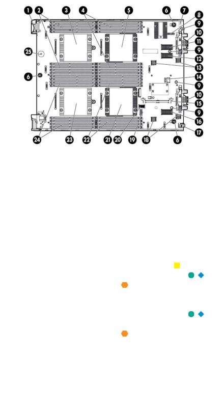
System board components
Item |
Description |
|
|
1 |
HP c-Class Blade SUV cable connector |
2 |
Processor 3 DIMM slots (8) |
3 |
Processor socket 3 (populated) |
4 |
Processor 1 DIMM slots (8) |
5 |
Processor socket 1 (populated) |
6 |
System board thumbscrew |
7 |
System maintenance switch |
8 |
TPM connector |
9 |
Mezzanine assembly guide pins |
10 |
Enclosure connector |
11 |
Mezzanine connector 1 (Type A mezzanine only) |
12 |
Mezzanine connector 2 (Type A or Type B mezzanine) |
13 |
FlexibleLOM 2 connectors (2) |
14 |
Internal USB connector |
15 |
Cache module connector |
16 |
Mezzanine connector 3 (Type A or Type B mezzanine) |
17 |
MicroSD card slot |
18 |
FlexibleLOM 1 connectors (2) |
19 |
Drive power connector |
20 |
Drive signal connector |
21 |
Processor socket 2 (populated) |
22 |
Processor 2 DIMM slots (8) |
23 |
Processor socket 4 (populated) |
24 |
Processor 4 DIMM slots (8) |
25 |
System battery |
The symbols 


 correspond to the symbols located on the interconnect bays. For more information, see the
HP ProLiant BL660c Gen8 Server Blade Installation Instructions on the HP website (http://www.hp.com/support).
Component identification 8
Mezzanine connector definitions
A PCIe x8 mezzanine connector supports x16 cards at up to x8 speeds.
Item |
PCIe |
|
|
Mezzanine connector 1 |
x8, Type A mezzanine card only |
Mezzanine connector 2 |
x16, Type A or B mezzanine card |
Mezzanine connector 3 |
x16, Type A or B mezzanine card |
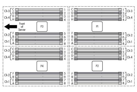
DIMM slot locations
DIMM slots are numbered sequentially (1 through 8) for each processor. The supported AMP modes use the alpha assignments for population order and the slot numbers designate the DIMM slot ID for spare replacement.
Component identification 9

Tool locations
Item Description
1DIMM tool
2T-15 Torx screwdriver
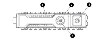
HP c-Class Blade SUV Cable
Item |
Connector |
Description |
|
|
|
1 |
Server blade |
For connecting to the SUV connector on the |
|
|
server blade front panel |
2 |
Video |
For connecting a video monitor |
3 |
USB |
For connecting up to two USB devices |
Component identification 10
Item |
Connector |
Description |
|
|
|
4 |
Serial |
For trained personnel to connect a null modem |
|
|
serial cable and perform advanced diagnostic |
|
|
procedures |
|
|
|
Component identification 11

Operations
Power up the server blade
The Onboard Administrator initiates an automatic power-up sequence when the server blade is installed. If the default setting is changed, use one of the following methods to power up the server blade:
•Use a virtual power button selection through iLO.
•Press and release the Power On/Standby button.
When the server blade goes from the standby mode to the full power mode, the system power LED changes from amber to solid green. The health status LED bar flashes green when the Power On/Standby Button service is being initialized. For more information about the system power LED status, see "Front panel LEDs ("Front panel LEDs and buttons" on page 6)."
For more information about the Onboard Administrator, see the enclosure setup and installation guide on the HP website (http://www.hp.com/support/oa).
For more information about iLO, see "HP iLO (on page 50)."
Power down the server blade
Before powering down the server blade for any upgrade or maintenance procedures, perform a backup of critical server data and programs.
IMPORTANT: When the server blade is in standby mode, auxiliary power is still being provided to the system.
Depending on the Onboard Administrator configuration, use one of the following methods to power down the server blade:
•Press and release the Power On/Standby button.
This method initiates a controlled shutdown of applications and the OS before the server blade enters standby mode.
•Press and hold the Power On/Standby button for more than 4 seconds to force the server blade to enter standby mode.
This method forces the server blade to enter standby mode without properly exiting applications and the OS. If an application stops responding, you can use this method to force a shutdown.
•Use a virtual power button selection through iLO.
This method initiates a controlled remote shutdown of applications and the OS before the server blade enters standby mode.
•Use the Onboard Administrator CLI to execute one of the following commands: o poweroff server [bay number]
This command initiates a controlled shutdown of applications and the OS before the server blade enters standby mode.
Operations 12

opoweroff server [bay number] force
This form of the command forces the server blade to enter standby mode without properly exiting applications and the OS. If an application stops responding, this method forces a shutdown.
•Use the Onboard Administrator GUI to initiate a shutdown:
a.Select the Enclosure Information tab.
b.In the Device Bays item, select the Overall checkbox.
c.From the Virtual Power menu, initiate a shutdown of applications and the OS:
—For a controlled shutdown, select Momentary Press.
—For an emergency shutdown, select Press and Hold.
Before proceeding, verify the server blade is in standby mode by observing that the system power LED is amber.
Remove the server blade
1.Identify the proper server blade.
2.Power down the server blade (on page 12).
3.Remove the server blade.
4.Place the server blade on a flat, level work surface.
WARNING: To reduce the risk of personal injury from hot surfaces, allow the drives and the internal system components to cool before touching them.
CAUTION: To prevent damage to electrical components, properly ground the server blade before beginning any installation procedure. Improper grounding can cause ESD.
Operations 13
Remove the access panel
To remove the component:
1.Power down the server blade (on page 12).
2.Remove the server blade (on page 13).
3.Press the access panel release button.
4.Slide the access panel towards the rear of the server blade, and then lift to remove the panel.
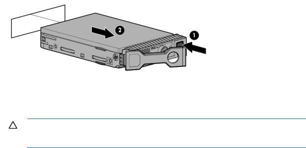
Remove a drive
1.Back up all server blade data on the drive.
2.Remove the drive.
Removing DIMM baffles
CAUTION: To avoid damage to the server blade and the enclosure, install all DIMM baffles in the proper location after adding or replacing DIMMs. DIMM baffles that are missing or installed incorrectly can compromise server blade and enclosure cooling.
The server blade contains three DIMM baffles.
Remove the center DIMM baffle
To remove the component:
1.Power down the server blade (on page 12).
2.Remove the server blade (on page 13).
3.Remove the access panel (on page 14).
4.Disconnect any cables that may be routed across the DIMM baffle.
Operations 14
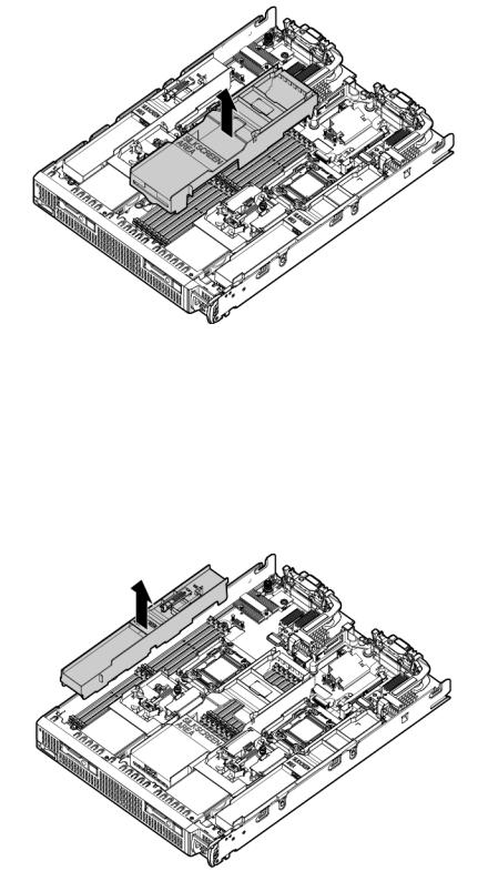
5.Remove the center DIMM baffle.
Remove the left DIMM baffle
To remove the component:
1.Power down the server blade (on page 12).
2.Remove the server blade (on page 13).
3.Remove the access panel (on page 14).
4.Disconnect any cables that may be routed across the DIMM baffle.
5.Remove the left DIMM baffle.
Operations 15
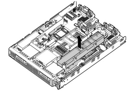
Remove the right DIMM baffle
To remove the component:
1.Power down the server blade (on page 12).
2.Remove the server blade (on page 13).
3.Remove the access panel (on page 14).
4.Disconnect any cables that may be routed across the DIMM baffle.
5.Remove the right DIMM baffle.
Remove the front panel/drive cage assembly
To remove the component:
1.Power down the server blade (on page 12).
2.Remove the server blade (on page 13).
3.Remove the access panel (on page 14).
4.Remove all drives ("Remove a drive" on page 14).
5.Remove all DIMM baffles ("Removing DIMM baffles" on page 14).
6.Remove all FBWC capacitor packs ("FBWC capacitor pack options" on page 39).
7.Disconnect the signal cable and the power cable from the SAS backplane.
Operations 16
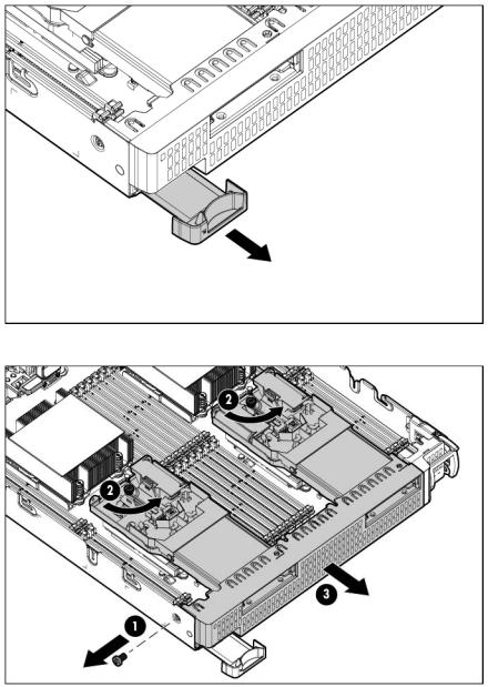
8.Extend the serial label pull tab.
9.Remove the front panel/drive cage assembly.
Remove the FBWC capacitor pack
To remove the component:
1.Power down the server blade (on page 12).
2.Remove the server blade (on page 13).
3.Remove the access panel (on page 14).
4.Locate the capacitor pack on the drive cage. For more information, see "FBWC capacitor pack cabling (on page 46)."
Operations 17
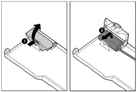
5.Remove the capacitor pack from the carrier.
Operations 18
Setup
Installing an HP BladeSystem c-Class enclosure
Before performing any server blade-specific procedures, install an HP BladeSystem c-Class enclosure.
The most current documentation for server blades and other HP BladeSystem components is available at the HP website (http://www.hp.com/go/bladesystem/documentation).
Documentation is also available in the following locations:
•Documentation CD that ships with the enclosure
•HP website (http://www.hp.com/go/bizsupport)
Preparing the enclosure
HP BladeSystem enclosures ship with device bay dividers to support half-height devices. To install a full-height device, remove the blanks and the corresponding device bay divider.
CAUTION: To prevent improper cooling and thermal damage, do not operate the server blade or the enclosure unless all drive and device bays are populated with either a component or a blank.
IMPORTANT: For optimal cooling and system performance, configure the c7000 enclosure with ten fans and configure the c3000 enclosure with six fans.
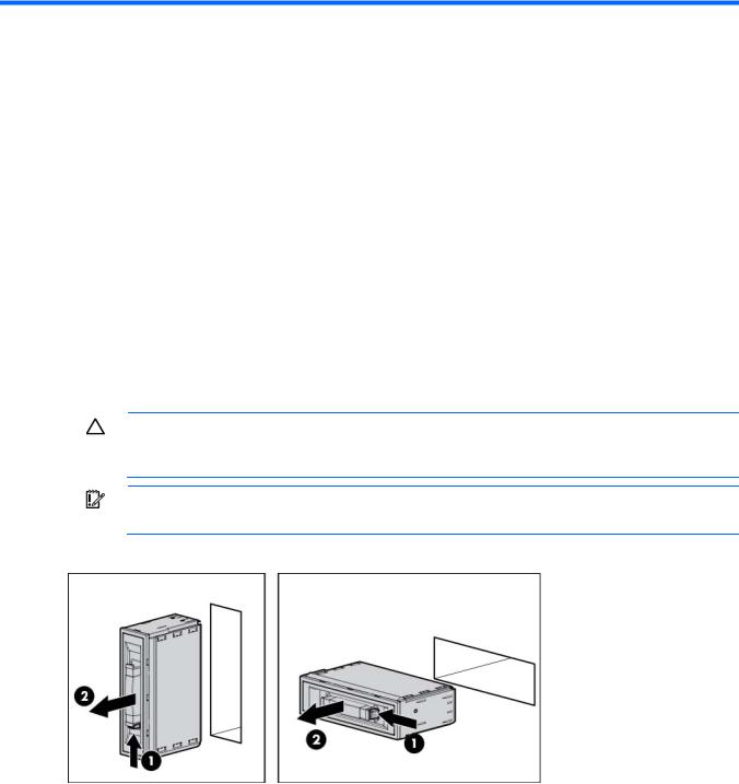
1.Remove the device bay blank.
2.Remove the three adjacent blanks.
Setup 19
Removing a c7000 device bay divider
1.Slide the device bay shelf locking tab to the left to open it.
2.Push the device bay shelf back until it stops, lift the right side slightly to disengage the two tabs from the divider wall, and then rotate the right edge downward (clockwise).
Setup 20
3.Lift the left side of the device bay shelf to disengage the three tabs from the divider wall, and then remove it from the enclosure.
Removing a c3000 device bay mini-divider or device bay divider
1.Slide the locking tab down.
2.Remove the mini-divider or divider: o c3000 mini-divider:
Setup 21
Push the divider toward the back of the enclosure until the divider drops out of the chassis.
o c3000 divider:
a.Push the divider toward the back of the enclosure until it stops.
b.Slide the divider to the left to disengage the tabs from the wall.
c.Rotate the divider clockwise.
d.Remove the divider from the enclosure.
Installing interconnect modules
For specific steps to install interconnect modules, see the documentation that ships with the interconnect module.
Setup 22

Interconnect bay numbering and device mapping
•HP BladeSystem c7000 Enclosure
•HP BladeSystem c3000 Enclosure
To support network connections for specific signals, install an interconnect module in the bay corresponding to the embedded adapter or mezzanine signals.
Server blade signal |
c7000 interconnect bay |
c3000 interconnect bay |
Interconnect bay labels |
|
|
|
|
|
|
FlexibleLOM 1 |
1 |
1 |
|
|
(Embedded) |
|
|
|
|
FlexibleLOM 2 |
2 |
1 |
|
|
(Embedded) |
|
|
|
|
Mezzanine 1 |
3 and 4 |
2 |
|
|
|
|
|
|
|
Mezzanine 2 |
5 and 6* |
3 and 4 |
|
|
|
7 and 8** |
3 and 4 |
|
|
|
|
|
|
|
|
|
|
Setup 23 |
|
Server blade signal |
c7000 interconnect bay |
c3000 interconnect bay |
Interconnect bay labels |
|
|
|
|
Mezzanine 3 |
5 and 6** |
3 and 4 |
|
|
7 and 8* |
3 and 4 |
|
|
|
|
|
*Dual port mezzanine card ports and four-port mezzanine card ports 1 and 2
**Four-port mezzanine card ports 3 and 4
For detailed port mapping information, see the HP BladeSystem enclosure installation poster or the HP BladeSystem enclosure setup and installation guide on the HP website (http://www.hp.com/go/bladesystem/documentation).
Connecting to the network
To connect the HP BladeSystem to a network, each enclosure must be configured with network interconnect devices to manage signals between the server blades and the external network.
Two types of interconnect modules are available for HP BladeSystem c-Class enclosures: Pass-Thru modules and switch modules. For more information about interconnect module options, see the HP website (http://www.hp.com/go/bladesystem/interconnects).
IMPORTANT: To connect to a network with a Pass-Thru module, always connect the Pass-Thru module to a network device that supports Gigabit or 10 Gb speed, depending on the corresponding Pass-Thru model.
Installing server blade options
Before installing and initializing the server blade, install any server blade options, such as an additional processor, hard drive, or mezzanine card.
Installing a server blade
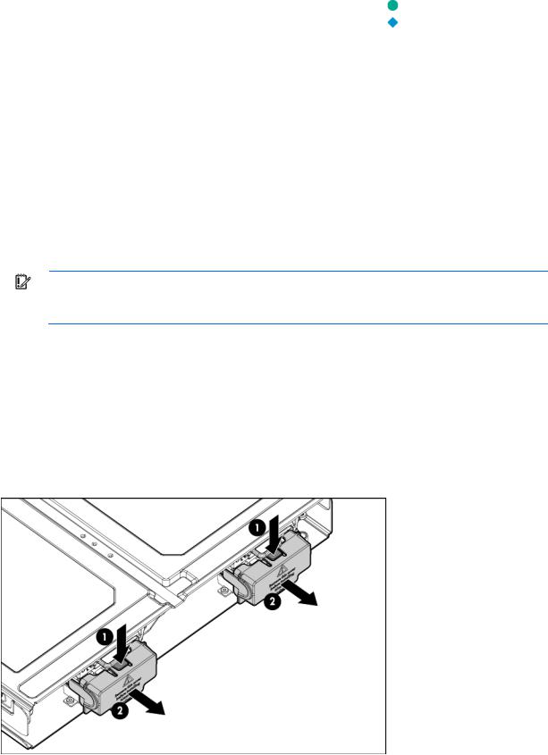
1.Remove the connector covers.
Setup 24
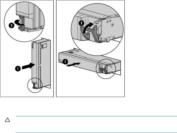
2.Install the server blade.
Assembling a full height blank
CAUTION: To prevent improper cooling and thermal damage, do not operate the server blade or the enclosure unless all drive and device bays are populated with either a component or a blank.
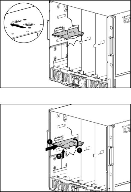
1.Obtain the coupler plate:
o If you are using a device bay blank that came with the enclosure, the coupler plate can be found with the contents of the full-height device shipping box.
o If you are using a device bay blank that you purchased as an option, remove the coupler plate from inside the blank.
Setup 25
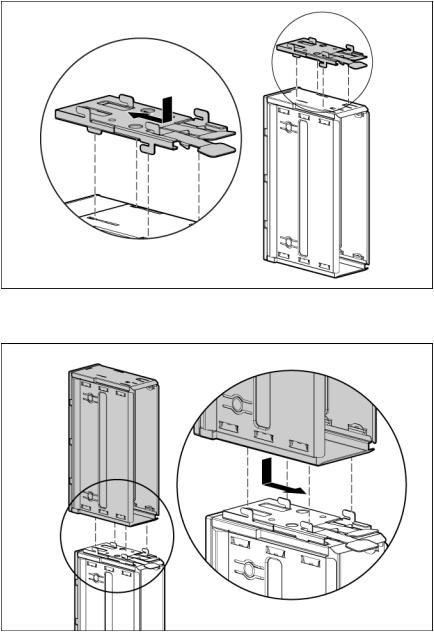
2.Fit the coupler plate into the slots on top of the blank, and then slide the coupler plate back until it snaps into place.
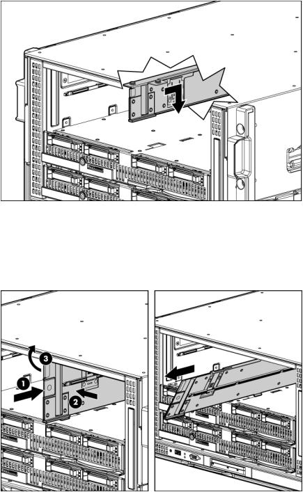
3.Fit the slots on the bottom of the second blank on to the tabs on the coupler plate, and then slide the second blank forward until it snaps in place.
4.Install the full-height blank into the device bay.
Completing the configuration
To complete the server blade and HP BladeSystem configuration, see the overview card that ships with the enclosure.
Setup 26

Hardware options installation
Introduction
If more than one option is being installed, read the installation instructions for all the hardware options and identify similar steps to streamline the installation process.
WARNING: To reduce the risk of personal injury from hot surfaces, allow the drives and the internal system components to cool before touching them.
CAUTION: To prevent damage to electrical components, properly ground the server before beginning any installation procedure. Improper grounding can cause electrostatic discharge.
Drive option
The server blade supports up to two SAS, SATA, or solid state drives.
CAUTION: To prevent improper cooling and thermal damage, do not operate the server blade or the enclosure unless all drive and device bays are populated with either a component or a blank.
1.Remove the drive blank.
Hardware options installation 27
Loading...