


 Loading...
HP 2000 Notebook PC
Compaq Presario CQ58
Notebook PC
Maintenance and Service Guide
SUMMARY
This guide is a troubleshooting reference used for maintaining and servicing the computer. It provides comprehensive information on identifying computer features, components, and spare parts; troubleshooting computer problems; and performing computer disassembly procedures.
© Copyright 2012 Hewlett-Packard
Development Company, L.P.
ATI and ATI Mobility Radeon are trademarks of Advanced Micro Devices, Inc. Bluetooth is a trademark owned by its proprietor and used by Hewlett-Packard Company under license. Intel, Pentium, and Core are trademarks of Intel corporation in the U.S. and other countries. Microsoft and Windows are U.S. registered trademarks of Microsoft Corporation.
The information contained herein is subject to change without notice. The only warranties for HP products and services are set forth in the express warranty statements accompanying such products and services. Nothing herein should be construed as constituting an additional warranty. HP shall not be liable for technical or editorial errors or omissions contained herein.
First Edition: October 2012
Document Part Number: 698902-001

Safety warning notice
WARNING! To reduce the possibility of heat-related injuries or of overheating the computer, do not place the computer directly on your lap or obstruct the computer air vents. Use the computer only on a hard, flat surface. Do not allow another hard surface, such as an adjoining optional printer, or a soft surface, such as pillows or rugs or clothing, to block airflow. Also, do not allow the AC adapter to contact the skin or a soft surface, such as pillows or rugs or clothing, during operation. The computer and the AC adapter comply with the user-accessible surface temperature limits defined by the International Standard for Safety of Information Technology Equipment (IEC 60950).
iii
iv Safety warning notice

Table of contents
1 |
Product description ........................................................................................................... |
1 |
2 |
External component identification ..................................................................................... |
4 |
|
Finding your hardware and software information ......................................................................... |
4 |
|
Locating hardware .................................................................................................... |
4 |
|
Locating software ..................................................................................................................... |
4 |
|
Right side ................................................................................................................................ |
4 |
|
Left side .................................................................................................................................. |
5 |
|
Front ....................................................................................................................................... |
6 |
|
Display ................................................................................................................................... |
7 |
|
Top ........................................................................................................................................ |
8 |
|
TouchPad ................................................................................................................. |
8 |
|
Lights ....................................................................................................................... |
9 |
|
Button .................................................................................................................... |
10 |
|
Keys ...................................................................................................................... |
11 |
|
Bottom .................................................................................................................................. |
12 |
3 |
Illustrated parts catalog .................................................................................................. |
13 |
|
Serial number location ............................................................................................................ |
13 |
|
Computer major components ................................................................................................... |
14 |
|
Display assembly components ................................................................................................. |
17 |
|
Mass storage devices ............................................................................................................. |
19 |
|
Miscellaneous parts ................................................................................................................ |
20 |
|
Sequential part number listing .................................................................................................. |
21 |
4 |
Removal and replacement procedures ............................................................................ |
23 |
|
Preliminary replacement requirements ....................................................................................... |
23 |
|
Tools required ......................................................................................................... |
23 |
|
Service considerations ............................................................................................. |
23 |
|
Plastic parts ............................................................................................. |
23 |
|
Cables and connectors ............................................................................. |
24 |
|
Drive handling ......................................................................................... |
24 |
|
Grounding guidelines .............................................................................................. |
25 |
|
Electrostatic discharge damage .................................................................. |
25 |
|
Packaging and transporting guidelines ........................................ |
26 |
|
Workstation guidelines .............................................................. |
26 |
v
|
Equipment guidelines ................................................................. |
27 |
|
Component replacement procedures ........................................................................................ |
28 |
|
Serial number ......................................................................................................... |
28 |
|
Computer feet ......................................................................................................... |
29 |
|
Battery ................................................................................................................... |
30 |
|
Service door ........................................................................................................... |
31 |
|
Hard drive ............................................................................................................. |
32 |
|
Optical drive .......................................................................................................... |
34 |
|
WLAN module ........................................................................................................ |
36 |
|
Memory module ...................................................................................................... |
37 |
|
RTC battery ............................................................................................................ |
38 |
|
Keyboard ............................................................................................................... |
39 |
|
Top cover ............................................................................................................... |
41 |
|
Power button board ................................................................................................. |
44 |
|
Speaker assembly ................................................................................................... |
45 |
|
TouchPad button board ............................................................................................ |
46 |
|
USB board ............................................................................................................. |
47 |
|
Security cable lock .................................................................................................. |
48 |
|
Power connector ..................................................................................................... |
49 |
|
Display assembly .................................................................................................... |
50 |
|
System board ......................................................................................................... |
57 |
|
Fan/heat sink assembly ........................................................................................... |
60 |
|
.............................................................................................................................. |
63 |
5 |
Specifications .................................................................................................................. |
64 |
|
Computer specifications .......................................................................................................... |
64 |
|
39.6-cm (15.6-in) display specifications .................................................................................... |
65 |
|
Hard drive specifications ........................................................................................................ |
66 |
|
DVD±RW and CD-RW SuperMulti Double-Layer Combo Drive specifications ................................. |
67 |
|
............................................................................................................................................ |
68 |
6 |
Using Setup Utility (BIOS) and System Diagnostics ........................................................... |
69 |
|
Starting Setup Utility (BIOS) ..................................................................................................... |
69 |
|
Updating the BIOS ................................................................................................................. |
69 |
|
Determining the BIOS version ................................................................................... |
69 |
|
Downloading a BIOS update .................................................................................... |
70 |
|
Using System Diagnostics ........................................................................................................ |
70 |
7 |
Backing up, restoring, and recovering ............................................................................ |
72 |
|
Creating recovery media and backups ..................................................................................... |
72 |
vi
|
Creating recovery media .......................................................................................... |
73 |
|
Restore and recovery .............................................................................................................. |
74 |
|
Using Windows Refresh for quick and easy recovery ................................................... |
76 |
|
Remove everything and reinstall Windows ................................................................. |
76 |
|
Recovering using HP Recovery Manager .................................................................... |
77 |
|
What you need to know ............................................................................ |
77 |
|
Using the recovery partition to recover a minimized image (select models |
|
|
only) ....................................................................................................... |
77 |
|
Using recovery media to recover ................................................................ |
78 |
|
Changing the computer boot order ............................................................. |
78 |
|
Removing the recovery partition ................................................................................ |
78 |
8 |
Power cord set requirements .......................................................................................... |
80 |
|
Requirements for all countries .................................................................................................. |
80 |
|
Requirements for specific countries and regions ......................................................................... |
81 |
9 |
Recycling ........................................................................................................................ |
83 |
Index ................................................................................................................................. |
84 |
|
vii
viii

1 Product description
Category |
Description |
AMD |
|
|
|
|
|
UMA |
|
|
|
|
HP Pavilion G6 Notebook PC |
√ |
|
|
|
Processors |
|
|
|
|
|
|
AMD C60 1.333 GHz/1.0 GHz, 1 MB L2 cache, 10666 MHz), Dual |
√ |
|
9 W |
|
|
|
|
|
AMD E300 (1.3 GHz, 1 MB L2 cache, 10666 MHz), Dual 18 W |
√ |
|
|
|
Chipset |
AMD A50M FCH |
√ |
|
|
|
Graphics |
AMD Radeon HD 6290 |
√ |
|
|
|
|
AMD Radeon HD 6310 |
√ |
|
|
|
Panel |
39.6-cm (15.6-in) HD LED BrightView (1366 x 768) |
√ |
|
|
|
|
16:9 wide aspect ratio |
√ |
|
|
|
Memory |
1 customer-accessible/upgradable SODIMM slots: |
|
|
|
|
|
● DDR3-10666 MHz Single Channel Support (DDR3L-1600/ |
√ |
|
DDR3-1333 downgrade to 1066) |
|
|
|
|
|
Supports up to 4GB of system memory in the following configurations: |
|
|
|
|
|
● 4096 MB (4096 MB × 1) |
√ |
|
|
|
|
● 2048 MB (2048 MB × 1) |
√ |
|
|
|
Hard drives |
Supports the following 7.0/9.5 mm, 6.35-cm (2.5 in) SATA hard |
|
|
drives: |
|
|
|
|
|
● 320 GB, 5400 rpm |
√ |
|
|
|
Optical drives |
12.7 mm (0.50-in) fixed SATA tray load |
√ |
|
|
|
|
DVD±RW and CD-RW SuperMulti Double-Layer Combo Drive |
√ |
|
|
|
|
Supports Zero-Power ODD |
√ |
|
|
|
Webcam |
HP TrueVision HD camera (1280x720 by 30 frames per second), fixed |
√ |
|
angle, with activity light and single digital microphone |
|
|
|
|
Audio |
High-definition audio supports: |
√ |
|
Microsoft® premium requirements with HP Altec Lansing speakers (2) |
|
|
SRS Premium Sound technology |
|
|
|
|
Ethernet |
Integrated 10/100 network interface card (NIC) |
√ |
|
|
|
1

Category |
Description |
AMD |
|
|
|
|
|
UMA |
|
|
|
|
Integrated wireless local area network (WLAN) options by way of |
√ |
|
wireless module and 1wireless antennas built into display assembly |
|
|
|
|
|
Supports the following WLAN formats: |
|
|
|
|
|
(802.11b/g/n) |
|
|
|
|
External media card |
Digital Media Slot supporting SD, SDHC, SDXC (UHS104 compliant), |
√ |
|
and MMC |
|
|
|
|
Internal card |
One half-size Mini Card slot for WLAN |
√ |
|
|
|
Ports |
Audio-in (digital microphone) |
√ |
|
|
|
|
Audio-out (stereo headphone) |
√ |
|
|
|
|
Hot plug/unplug with auto-detect for correct output to wide-aspect vs. |
√ |
|
standard aspect video |
|
|
|
|
|
RJ-45 (Ethernet) |
√ |
|
|
|
|
Three USB 2.0 ports |
√ |
|
|
|
|
VGA (Dsub 15-pin) supporting the following: |
√ |
|
● 2048 x 1536 external resolution @ 75 Hz |
|
|
● 2048 x 1536 external resolution @ 85 Hz |
|
|
|
|
|
AC Smart Pin adapter |
√ |
|
|
|
Keyboard/pointing |
39.62-cm (15.6-in), full-size, textured keyboard |
√ |
devices |
|
|
|
|
|
|
TouchPad with 2 buttons (multitouch gestures, 2-finger scrolling, pinch |
√ |
|
zoom, and taps enabled as default) |
|
|
|
|
Power requirements |
6-cell, 2.22 Ah, 47 Wh battery |
√ |
|
|
|
|
Batteries support fast charge |
√ |
|
|
|
|
65 W AC Smart adapter with localized cable plug support (1 M power |
√ |
|
cord) |
|
|
|
|
Security |
Security Lock |
√ |
|
|
|
Operating system |
Preinstalled: |
|
|
|
|
|
Windows 8® Standard (64 bit) |
√ |
|
|
|
Serviceability |
End-user replaceable parts: |
|
|
|
|
|
AC adapter |
√ |
|
|
|
|
Battery (system) |
√ |
|
|
|
|
Hard drive |
√ |
|
|
|
|
Memory module |
√ |
|
|
|
2 |
Chapter 1 Product description |
Category |
Description |
AMD |
|
|
|
|
|
UMA |
|
|
|
|
Optical drive |
√ |
|
|
|
|
WLAN cards |
√ |
|
|
|
3

2 External component identification
Finding your hardware and software information
Locating hardware
To find out what hardware is installed on your computer:
1.From the Start screen, type c, and then select Control Panel.
2.Select System and Security, and then in the System area, click Device Manager. A list displays all the devices installed in your computer.
Locating software
▲To find out what software is installed on your computer, from the Start screen, right-click using the mouse or swipe from the top of the TouchPad to display the apps and then select the All apps icon.
Right side
Component |
|
Description |
|
|
|
|
|
(1) |
Optical drive |
Reads and writes to an optical disc. |
|
|
|
|
|
(2) |
Optical drive light |
● |
Green or Amber: The optical drive is being accessed. |
|
Optical drive eject button |
● |
Off: The optical drive is idle. |
|
|
Optical drive eject button releases the disc tray. |
|
|
|
|
|
(3) |
USB 2.0 port |
Connects an optional USB device. |
|
|
|
|
|
4 |
Chapter 2 External component identification |

Component |
|
Description |
|
|
|
(4) |
Power connector |
Connects an AC adapter. |
|
|
|
(5) |
Security cable slot |
Attaches an optional security cable to the computer. |
|
|
NOTE: The security cable is designed to act as a |
|
|
deterrent, but it may not prevent the computer from being |
|
|
mishandled or stolen. |
|
|
|
Left side
Component |
|
Description |
|
|
|
(1) |
External monitor port |
Connects an external VGA monitor or projector. |
|
|
|
(2) |
Vents (2) |
Enable airflow to cool internal components. |
|
|
NOTE: The computer fan starts up automatically to cool |
|
|
internal components and prevent overheating. It is normal for |
|
|
the internal fan to cycle on and off during routine operation. |
|
|
|
(3) |
RJ-45 (network) jack |
Connects a network cable. |
|
|
|
(4) |
USB 2.0 (2) |
Connects an optional USB device. |
|
|
|
(5) |
Audio-in (microphone) jack |
Connects an optional computer headset microphone, stereo |
|
|
array microphone, or monaural microphone. |
|
|
|
Left side |
5 |

Component |
|
Description |
|
|
|
(6) |
Audio-out (headphone) jack |
Connects optional powered stereo speakers, headphones, |
|
|
earbuds, a headset, or a television audio cable. |
|
|
WARNING! To reduce the risk of personal injury, adjust |
|
|
the volume before using headphones, earbuds, or a headset. |
|
|
For additional safety information, see the Regulatory, Safety |
|
|
and Environmental Notices. |
|
|
NOTE: When a device is connected to a headphone jack, |
|
|
the computer speakers are disabled. |
|
|
|
(7) |
Digital Media slot |
Supports the following digital media card formats: |
|
|
● Secure Digital High Capacity (SDHC) Memory Card |
|
|
● Secure Digital (SD) Memory Card |
|
|
● Secure Digital Extended Capacity (SDxC) Memory Card |
|
|
● MultiMediaCard (MMC) |
|
|
|
Front
Component |
Description |
|
|
Speakers (2) |
Produce sound. |
|
|
6 |
Chapter 2 External component identification |

Display
Component |
Description |
|
|
|
|
(1) |
WLAN antennas (1)* |
Send and receive wireless signals to communicate with wireless |
|
|
local area networks (WLANs). |
|
|
|
(2) |
Internal microphone (1) |
Records sound. |
|
|
|
(3) |
Webcam |
Records video, captures still photographs, and allows video |
|
|
conferences and online chat by means of streaming video. |
|
|
To use the webcam, from the Start screen type, c, and then select |
|
|
CyberLink YouCam from the list of apps. |
|
|
|
(4) |
Webcam light |
On: The webcam is in use. |
*The antennas are not visible from the outside of the computer. For optimal transmission, keep the areas immediately around the antennas free from obstructions. For wireless regulatory notices, see the section of the Regulatory, Safety and Environmental Notices that applies to your country or region. To access this guide, select the HP Support Assistant app on the Start screen, select My computer, and then select User guides.
Display 7

Top
TouchPad
Component |
|
Description |
|
|
|
|
|
(1) |
TouchPad light |
● |
Amber: The TouchPad is off. |
|
|
● |
Off: The TouchPad is on . |
|
|
|
|
(2) |
TouchPad on/off button |
Turns the TouchPad on or off. |
|
|
|
|
|
(3) |
Left TouchPad button |
Functions like the left button on an external mouse. |
|
|
|
|
|
(4) |
TouchPad zone |
Moves the on-screen pointer and selects or activates items on |
|
|
|
the screen. |
|
|
|
NOTE: The TouchPad also supports Edge-swipe gestures. |
|
|
|
|
|
(5) |
Right TouchPad button |
Functions like the right button on an external mouse. |
|
|
|
|
|
8 |
Chapter 2 External component identification |
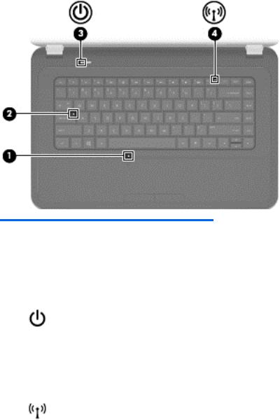
Lights
Component |
|
Description |
|
|
|
|
|
(1) |
TouchPad light |
● |
Amber: The TouchPad is off. |
|
|
● |
Off: The TouchPad is on. |
|
|
|
|
(2) |
Caps lock light |
White: Caps lock is on, which switches the keys to all capital |
|
|
|
letters. |
|
|
|
|
|
(3) |
Power light |
● |
White: The computer is on. |
|
|
● |
Blinking white: The computer is in the Sleep state, which |
|
|
|
is an energy-saving mode. The computer shuts off power |
|
|
|
to the display and other unneeded components. |
|
|
● |
Off: The computer is off or in Hibernation. Hibernation |
|
|
|
is an energy-saving mode that uses the least amount of |
|
|
|
power. |
|
|
|
|
(4) |
Wireless light |
● |
White: An integrated wireless device, such as a wireless |
|
|
|
local area network (WLAN) device, is on. |
|
|
● |
Amber: All wireless devices are off. |
|
|
|
|
Top 9

Button
Component |
Description |
|
|
|
|
Power button |
● |
When the computer is off, press the button to turn on |
|
|
the computer. |
|
● |
When the computer is on, press the button briefly to |
|
|
initiate Sleep (disabled by default). |
|
● |
When the computer is in the Sleep state, press the |
|
|
button briefly to exit Sleep. |
|
● |
When the computer is in Hibernation, press the button |
|
|
briefly to exit Hibernation. |
|
CAUTION: Pressing and holding the power button will |
|
|
result in the loss of unsaved information. |
|
|
If the computer has stopped responding and Microsoft® |
|
|
Windows® shutdown procedures are ineffective, press and |
|
|
hold the power button for at least 5 seconds to turn off the |
|
|
computer. |
|
|
To learn more about your power settings: |
|
|
1. |
From the Start screen, type power. |
|
2. |
Select Settings, and then select Power options. |
|
|
|
10 |
Chapter 2 External component identification |

Keys
Component |
|
Description |
|
|
|
(1) |
esc key |
Displays system information when pressed in combination |
|
|
with the fn key. |
|
|
|
(2) |
Windows logo key |
Displays the Windows Start menu. |
|
|
|
(3) |
Windows applications key |
Displays a shortcut menu for items beneath the cursor. |
|
|
|
(4) |
Action keys |
Execute frequently used system functions. |
|
|
|
Top 11

Bottom
Component |
|
Description |
|
|
|
(1) |
Battery bay |
Holds the battery. |
|
|
|
(2) |
Vents (5) |
Enable airflow to cool internal components. |
|
|
NOTE: The computer fan starts up automatically |
|
|
to cool internal components and prevent |
|
|
overheating. It is normal for the internal fan to cycle |
|
|
on and off during routine operation. |
|
|
|
(3) |
Battery release latch |
Releases the battery from the battery bay. |
(4) |
Wireless compartment, memory |
|
module compartment, solid-state drive |
|
(SSD)/hard drive bay. Also allows |
access to keyboard, and optical disk drive (ODD).
The service door provides access to the keyboard, ODD, SSD/hard drive bay, wireless compartment and memory module compartment.
CAUTION: To prevent an unresponsive system, replace the wireless module only with a wireless module authorized for use in the computer by the governmental agency that regulates wireless devices in your country or region. If you replace the module and then receive a warning message, remove the module to restore computer functionality, and then contact customer support through Help and Support.
12 |
Chapter 2 External component identification |
3 Illustrated parts catalog
Serial number location
When ordering parts or requesting information, provide the computer serial number and model number located in the battery bay of the computer.
Component |
Description |
|
|
|
|
(1) |
Product name |
The name affixed to the front of the computer. |
|
|
|
(2) |
Serial number (s/n) |
An alphanumeric identifier that is unique to each product. |
|
|
|
(3) |
Product number (p/n) |
This number provides specific information about the product’s |
|
|
hardware components. The product number helps a service |
|
|
technician to determine what components and parts are needed. |
|
|
|
(4) |
Warranty period |
The duration of the warranty period for the computer. |
|
|
|
(5) |
Model description (select models only) |
An alphanumeric identifier used to locate documents, drivers, and |
|
|
support for the computer. |
|
|
|
Serial number location |
13 |
 C2M29UA, C2M21UA User Manual")
Computer major components
14 |
Chapter 3 Illustrated parts catalog |

Item Description |
Spare part number |
(1)39.6-cm (15.6-in) HD, LED, BrightView (1366 x 768) display assembly:
NOTE: For more information on the display assembly internal component spare part information, see Display assembly components on page 17.
|
● For use in charcoal grey computer models |
639512-001 |
|
|
|
|
● For use in Pacific blue Compaq computer models only |
701769-001 |
|
|
|
|
● For use in black HP computer models only |
707798-001 |
|
|
|
(2) |
Keyboard (includes keyboard cable): |
|
|
|
|
|
● For use in the United States, Black (Windows 8) |
698694-001 |
|
|
|
|
● For use in Canada (French), Black (Windows 8) |
698694-DB1 |
|
|
|
(3) |
Top cover (includes TouchPad board): |
|
|
|
|
|
● For use in charcoal grey HP computer models |
701883-001 |
|
|
|
|
● For use in Pacific blue Compaq computer models |
701884-001 |
|
|
|
|
● For use in charcoal grey computer models |
639532-001 |
|
|
|
(4) |
Power connector (includes cable) |
640891-001 |
|
|
|
(5) |
USB board |
640883-001 |
|
|
|
(6) |
Power button board |
640884-001 |
|
|
|
(7) |
System board (includes replacement thermal material): |
|
|
|
|
|
● For use in AMD E300 UMA computer models |
701764-501 |
|
|
|
|
● For use in AMD C60 UMA computer models |
701765-501 |
|
|
|
(8) |
Fan/heat sink assembly (includes replacement thermal material): |
|
|
|
|
|
● For use in AMD A50M UMA computer models |
657145-001 |
|
|
|
(9) |
Speaker assembly (includes cable) |
639573-001 |
|
|
|
(10) |
RTC battery (includes mounting adhesive) |
449137-001 |
|
|
|
(11) |
Optical drive activity board |
640883-001 |
|
|
|
(12) |
TouchPad button board |
640885-001 |
|
|
|
(13) |
Base enclosure |
701881-001 |
|
|
|
(14) |
WLAN module |
|
|
|
|
|
● Ralink RT5390R 802.11 b/g/n 1×1 WiFi |
691415-001 |
|
|
|
(15) |
Optical drive cable |
640886-001 |
|
|
|
(16) |
Memory modules (1333 MHz, DDR3) |
|
|
|
|
|
● 4 GB PC3 10600 1333 MHz shared |
641369-001 |
|
|
|
|
● 2 GB PC3 10600 1333 MHz shared |
652972-001 |
|
|
|
(17) |
Hard drive connector cable |
644525-001 |
|
|
|
Computer major components |
15 |

Item |
Description |
Spare part number |
|
|
|
(18) |
Hard drive |
|
|
|
|
|
Supports the following 9.5 mm / 7.0 mm, 6.35 cm (2.5 in) SATA hard drives: |
|
|
|
|
|
● 320 GB, 7200 rpm |
634862-001 |
|
|
|
|
● Hard Drive Hardware Kit (not illustrated, includes bracket and screws). |
640878-001 |
|
|
|
(19) |
Optical drive (select models only) (includes optical drive bezel and bracket) |
|
|
|
|
|
DVD±RW and CD-RW SuperMulti Double-Layer Combo Drive |
660833-001 |
|
|
|
(20) |
Battery |
|
|
|
|
|
● 6-cell Li-lon, 2.20 Ah, 47 Wh |
593553-001 |
|
|
|
(21) |
Service door (included in plastics kit) |
640889-001 |
|
|
|
|
Rubber Kit (not illustrated, includes bumper and rubber feet) |
639572-001 |
|
|
|
16 |
Chapter 3 Illustrated parts catalog |

Display assembly components
Item |
Description |
Spare part number |
|
|
|
(1) |
Display bezel |
|
|
|
|
|
● Black |
639509-001 |
|
|
|
|
● For use in Compaq computer models |
701766-001 |
|
|
|
|
● For use in HP computer models |
701882-001 |
|
|
|
(2) |
Webcam module (high definition) |
708150-001 |
|
|
|
(3) |
39.6-cm (15.6-in) high-definition, BrightView LED display panel |
641663-001 |
|
|
|
(4) |
Display hinges |
639511-001 |
|
|
|
(5) |
Display hinge covers |
640887-001 |
|
|
|
(6) |
Display cable |
639510-001 |
|
|
|
(7) |
Wireless antenna (includes wireless antenna transceivers and cable) |
639499-001 |
|
|
|
Display assembly components |
17 |

Item |
Description |
Spare part number |
|
|
|
|
|
701878-001 |
|
|
|
(8) |
Display back cover (includes logo): |
|
|
|
|
|
● For use in charcoal grey computer models |
639501-001 |
|
|
|
|
● For use in Pacific blue Compaq computer models |
701880-001 |
|
|
|
|
● For use in black HP computer models |
701879-001 |
|
|
|
|
Display Screw Kit (not illustrated) |
640881-001 |
|
|
|
|
Display Rubber Kit (not illustrated, includes display bumper strips) |
640882-001 |
|
|
|
18 |
Chapter 3 Illustrated parts catalog |
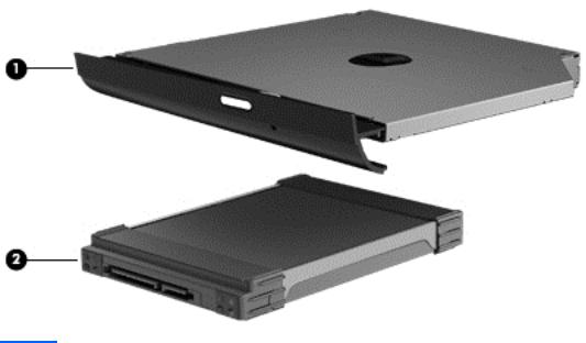
Mass storage devices
Item |
Description |
Spare part number |
|
|
|
(1) |
Hard drive |
|
|
|
|
|
Supports the following 9.5 mm, 6.3 cm (2.5 in) SATA hard drives: |
|
|
|
|
|
● 320 GB, 7200 rpm |
634862-001 |
|
|
|
|
Hard Drive Hardware Kit (not illustrated, includes bracket and screws) |
640878-001 |
|
|
|
(2) |
Optical drive (select models only), (12.7 mm, SATA, fixed, includes bezel and bracket) |
|
|
|
|
|
DVD±RW and CD-RW SuperMulti Double-Layer Combo Drive |
660833-001 |
|
|
|
Mass storage devices |
19 |

Miscellaneous parts
Description |
Spare part number |
|
|
AC adapters |
|
|
|
● 65 W AC adapter |
609939-001 |
|
|
Power cord, AC, 3 wire, black, 1.83-m |
490371-001 |
|
|
Thermal pads kit |
634366-001 |
|
|
Screw kit |
640879-001 |
● Phillips 2.0 x 2.0 (pan head) screw
● Phillips 3.0 x 1.5 screw
● Phillips 3.0 x 2.0 screw
● Phillips 3.0 x 3.0 screw
● Phillips 4.0 x 2.0 (captive) screw
● Phillips 6.0 x 2.5 screw
● Phillips 10.0 x 2.0 (captive) screw
20 |
Chapter 3 Illustrated parts catalog |

Sequential part number listing
Spare part number |
Description |
|
|
449137-001 |
RTC battery (includes mounting adhesive) |
|
|
490371-001 |
Power cord, AC, 3 wire, black, 1.83-m |
|
|
593553-001 |
Battery, 6-cell, 2.20 Ah, 47 Wh |
|
|
609939-001 |
65 W AC adapter |
|
|
634366-001 |
Thermal pads kit |
|
|
634862-001 |
320 GB, 7200 rpm, 7.0 mm, 6.35 cm (2.5 in) SATA hard drive |
|
|
639499-001 |
Wireless antenna (includes wireless antenna transceivers and cable) |
|
|
639501-001 |
Display back cover (includes logo) for use in Charcoal Grey computer models |
|
|
639509-001 |
Display bezel, Black |
|
|
639510-001 |
Display cable |
|
|
639511-001 |
Display hinges |
|
|
639512-001 |
39.6 cm (15.6 in) HD LED BrightView (1366 x 768) display assembly for use in Charcoal Grey |
|
computer models |
|
|
639532-001 |
Top cover (includes TouchPad board) for use in Charcoal Grey computer models |
|
|
639572-001 |
Rubber Kit (includes bumper and rubber feet) |
|
|
639573-001 |
Speaker assembly (includes cable) |
|
|
640878-001 |
Hard Drive Hardware Kit (includes bracket and screws) |
|
|
640879-001 |
Screw Kit |
|
|
640881-001 |
Display Screw Kit |
|
|
640882-001 |
Display Rubber Kit, Black (includes display bumper strips) |
|
|
640883-001 |
USB board |
|
|
640884-001 |
Power button board |
|
|
640885-001 |
TouchPad button board (includes bracket and cable) |
|
|
640886-001 |
Optical drive board |
|
|
640887-001 |
Display hinge covers |
|
|
640889-001 |
Plastics Kit (includes service door) |
|
|
640891-001 |
Power connector (includes cable) |
|
|
641369-001 |
4 GB memory PC3 12800 1600 Mhz Shared |
|
|
641663-001 |
39.6 cm (15.6-in) high-definition, BrightView LED display panel |
|
|
644525-001 |
Hard drive connector board |
|
|
652972-001 |
2 GB memory PC3 12800 1600 Mhz Shared |
|
|
Sequential part number listing |
21 |
Loading...