


 Loading...
HP BladeSystem c7000 Enclosure
Setup and Installation Guide
Abstract
This guide describes identification, operations, setup, configuration and utilities, troubleshooting, regulatory notices, specifications, and technical support. This guide is for an experienced service technician. HP assumes you are qualified in the servicing of computer equipment, trained in recognizing hazards in products, and are familiar with weight and stability precautions.
Part Number: 411272-401
February 2013
Edition: 10
© Copyright 2006, 2013 Hewlett-Packard Development Company, L.P.
The information contained herein is subject to change without notice. The only warranties for HP products and services are set forth in the express warranty statements accompanying such products and services. Nothing herein should be construed as constituting an additional warranty. HP shall not be liable for technical or editorial errors or omissions contained herein.

Contents |
|
Planning the installation................................................................................................................. |
6 |
Verifying the pallet contents ........................................................................................................................ |
6 |
Rack requirements ..................................................................................................................................... |
7 |
Rack-free environment requirements ............................................................................................................. |
8 |
Warning, caution, and important messages.................................................................................................. |
8 |
Space and airflow requirements ................................................................................................................ |
10 |
Temperature requirements ........................................................................................................................ |
11 |
Power requirements ................................................................................................................................. |
11 |
Grounding requirements........................................................................................................................... |
11 |
Component and LED identification ................................................................................................ |
12 |
Enclosure front components ...................................................................................................................... |
12 |
Power supply bay numbering .......................................................................................................... |
13 |
Power supply LEDs......................................................................................................................... |
13 |
Device bay numbering ................................................................................................................... |
14 |
HP BladeSystem Insight Display components ..................................................................................... |
15 |
Location Discovery Services ............................................................................................................ |
15 |
Enclosure rear components ....................................................................................................................... |
16 |
Fan bay numbering ....................................................................................................................... |
17 |
Fan LED........................................................................................................................................ |
18 |
Onboard Administrator components ................................................................................................ |
18 |
HP c7000 Onboard Administrator with KVM components .................................................................. |
19 |
Interconnect bay numbering............................................................................................................ |
20 |
Installation ................................................................................................................................. |
21 |
Installation overview ................................................................................................................................ |
21 |
Disassembling the enclosure ..................................................................................................................... |
21 |
Rack-free installation ................................................................................................................................ |
24 |
Rack installation ...................................................................................................................................... |
24 |
Measuring with the rack template .................................................................................................... |
25 |
Installing the rack rails.................................................................................................................... |
25 |
Installing the enclosure into the rack ................................................................................................. |
26 |
Installing the rear cage into the enclosure ......................................................................................... |
28 |
Component installation ............................................................................................................................ |
29 |
Installing a power supply................................................................................................................ |
29 |
Installing blades ............................................................................................................................ |
31 |
Connecting locally to a server blade with video and USB devices ........................................................ |
40 |
Installing fans................................................................................................................................ |
42 |
Installing Onboard Administrator modules ........................................................................................ |
44 |
Installing interconnect modules ........................................................................................................ |
46 |
Cabling and powering up the enclosure ........................................................................................ |
56 |
Cabling the enclosure .............................................................................................................................. |
56 |
Onboard Administrator cabling....................................................................................................... |
56 |
Enclosure link cabling .................................................................................................................... |
57 |
Cabling a PC to the enclosure service port........................................................................................ |
58 |
Cabling the network to the enclosure ............................................................................................... |
59 |
Contents |
3 |
Powering up the enclosure........................................................................................................................ |
59 |
Single-phase AC configuration ........................................................................................................ |
59 |
Three-phase AC configuration ......................................................................................................... |
64 |
HP BladeSystem Insight Display .................................................................................................... |
65 |
Insight Display overview........................................................................................................................... |
65 |
Running the Insight Display installation steps ............................................................................................... |
65 |
Navigating the Insight Display .................................................................................................................. |
69 |
Health Summary screen.................................................................................................................. |
70 |
Enclosure Settings screen................................................................................................................ |
73 |
Enclosure Info screen ..................................................................................................................... |
73 |
Blade and Port Info screen .............................................................................................................. |
74 |
Turn Enclosure UID On/Off screen................................................................................................... |
75 |
View User Note screen................................................................................................................... |
77 |
Chat Mode screen ......................................................................................................................... |
77 |
Troubleshooting .......................................................................................................................... |
78 |
Troubleshooting resources ........................................................................................................................ |
78 |
Important safety information...................................................................................................................... |
78 |
Symbols on equipment ................................................................................................................... |
78 |
Warnings and cautions .................................................................................................................. |
79 |
Insight Display errors ............................................................................................................................... |
80 |
Power errors ................................................................................................................................. |
80 |
Cooling errors............................................................................................................................... |
81 |
Location errors .............................................................................................................................. |
81 |
Configuration errors....................................................................................................................... |
81 |
Device failure errors....................................................................................................................... |
81 |
Support and other resources ........................................................................................................ |
83 |
Before you contact HP.............................................................................................................................. |
83 |
HP contact information............................................................................................................................. |
83 |
Customer Self Repair ............................................................................................................................... |
83 |
Regulatory compliance notices ..................................................................................................... |
91 |
Regulatory compliance identification numbers ............................................................................................. |
91 |
Federal Communications Commission notice............................................................................................... |
91 |
FCC rating label............................................................................................................................ |
91 |
FCC Notice, Class A Equipment ...................................................................................................... |
91 |
FCC Notice, Class B Equipment ...................................................................................................... |
91 |
Declaration of conformity for products marked with the FCC logo, United States only....................................... |
92 |
Modifications.......................................................................................................................................... |
92 |
Cables................................................................................................................................................... |
92 |
Canadian notice (Avis Canadien).............................................................................................................. |
92 |
European Union regulatory notice ............................................................................................................. |
93 |
Disposal of waste equipment by users in private households in the European Union ......................................... |
93 |
Japanese notice ...................................................................................................................................... |
94 |
BSMI notice ............................................................................................................................................ |
94 |
Korean notice ......................................................................................................................................... |
94 |
Chinese notice ........................................................................................................................................ |
95 |
Laser compliance .................................................................................................................................... |
95 |
Battery replacement notice........................................................................................................................ |
95 |
Taiwan battery recycling notice................................................................................................................. |
96 |
Power cord statement for Japan................................................................................................................. |
96 |
Electrostatic discharge................................................................................................................. |
97 |
Contents |
4 |
Preventing electrostatic discharge .............................................................................................................. |
97 |
Grounding methods to prevent electrostatic discharge.................................................................................. |
97 |
Acronyms and abbreviations........................................................................................................ |
98 |
Documentation feedback ........................................................................................................... |
100 |
Index....................................................................................................................................... |
101 |
Contents 5
Planning the installation
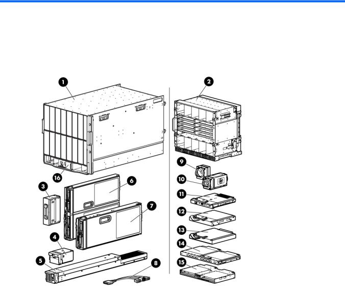
Verifying the pallet contents
Item |
Name |
Description |
|
|
|
1 |
HP BladeSystem c7000 Enclosure |
The HP BladeSystem enclosure |
2 |
Rear cage |
The rear section of the enclosure |
3 |
Device bay blank |
A mandatory insert installed in any unused device bay |
4 |
Power supply blank |
A mandatory insert installed in any unused power |
|
|
supply bay |
5 |
Enclosure hot-plug power supply (quantity |
The power supply for the enclosure |
|
as ordered) |
|
6 |
Full-height device (quantity as ordered) |
The full-height server or storage blade |
7 |
Half-height device (quantity as ordered) |
The half-height server or storage blade |
8 |
Local I/O cable |
A cable with serial, USB, and video connectors that |
|
|
connects to the I/O connector on the front of a blade |
|
|
|
9 |
Fan blank |
A mandatory insert installed in any unused fan bay |
10 |
HP Active Cool 200 Fan (quantity as |
A fan used to cool the components installed in the |
|
ordered) |
enclosure |
Planning the installation 6

Item |
Name |
Description |
|
|
|
11 |
Onboard Administrator module |
Hot-pluggable enclosure management module. One |
|
|
module is required to manage the components |
|
|
installed in the enclosure. To provide redundant |
|
|
enclosure management, you can install an optional |
|
|
second module. |
|
|
|
12 |
Onboard Administrator blank |
A mandatory cover installed in any unused Onboard |
|
|
Administrator bay |
13 |
Interconnect blank |
A mandatory insert installed in any unused |
|
|
interconnect bay |
|
|
|
14 |
Interconnect module (quantity and type as |
Any of several components, such as pass-thrus or |
|
ordered) |
switches that enable communication between the |
|
|
blade and the enclosure |
|
|
|
15 |
Onboard Administrator tray |
Hot-pluggable tray that houses up to two Onboard |
|
|
Administrator modules and provides two enclosure link |
|
|
connectors, the rear enclosure UID, LED, and switch. |
|
|
|
16 |
HP BladeSystem Insight Display |
A display that provides information about the health |
|
|
and operation of the enclosure |
17* |
Power retention ties (single-phase enclosures |
Tie straps that help prevent single-phase power cables |
|
only) |
from disconnecting from the power connectors |
|
|
|
18* |
Documentation CD |
A CD containing detailed documentation on using the |
|
|
enclosure |
|
|
|
19* |
Hard copy installation instructions for |
The printed installation instructions |
|
blades, options, and interconnects |
|
20* |
Installation checklist |
A checklist to guide you through installation of the |
|
|
enclosure and components |
|
|
|
* Not shown |
|
|
Rack requirements
The enclosure is compatible with the following racks:
•All HP 10000 and 10000G2 Series racks except the HP 10614 rack. NOTE: The system is optimized for 10000 Series racks.
•Telco racks
•Third-party rack cabinets that meet the following requirements: o Width: 48.3 cm (19 in)
o Depth:
—88.9 cm (35 in) maximum clearance between front and rear RETMA rails
—62.7 cm (24.7 in) minimum clearance for round-hole racks
—63.5 cm (25 in) minimum clearance for square-hole racks
oClearance—7.6 cm (3 in) minimum clearance between rear RETMA rails and rear rack door to accommodate system cabling
o Clearance—4.5 cm (1.75 in) minimum clearance between rack face and inside of front rack door
Planning the installation 7

oOpen area—Minimum of 65 percent open area to provide adequate airflow through any rack front or rear doors
oAdjustable rack rails are shipped with each enclosure:
—Minimum rail length: 63.5 cm (25 in)
—Maximum rail length: 86.4 cm (34 in)
Rack-free environment requirements
The HP BladeSystem c7000 Enclosure (referred to as the enclosure) can be used in a rack-free environment. The following conditions must be met when performing a rack-free installation:
•A fully-populated enclosure can weigh up to 217.7 kg (480 lb). The object supporting the enclosure must be able to withstand this weight.
•The enclosure should be supported by a sturdy, flat surface.
WARNING: To reduce the risk of personal injury or damage to the equipment in a rack-free environment:
•Never stack the enclosure on top of another enclosure.
•Never place equipment on top of the enclosure.
•Never place the enclosure on a surface that cannot support up to 217.7 kg (480 lb).
Warning, caution, and important messages
WARNING: To reduce the risk of personal injury or damage to equipment, heed all warnings and cautions throughout the installation instructions.
WARNING: To reduce the risk of personal injury or damage to the equipment, be sure that:
•The leveling jacks are extended to the floor.
•The full weight of the rack rests on the leveling jacks.
•The stabilizing feet are attached to the rack if it is a single-rack installation.
•The racks are coupled together in multiple-rack installations.
•Only one component is extended at a time. A rack may become unstable if more than one component is extended for any reason.
WARNING: To reduce the risk of personal injury or equipment damage when unloading a rack:
•At least two people are needed to safely unload the rack from the pallet. An empty 42U rack can weigh as much as 115 kg (253 lb), can stand more than 2.1 m (7 ft) tall, and might become unstable when being moved on its casters.
•Never stand in front of the rack when it is rolling down the ramp from the pallet. Always handle the rack from both sides.
Planning the installation 8
WARNING: The enclosure is very heavy. To reduce the risk of personal injury or damage to the equipment:
•Observe local occupational health and safety requirements and guidelines for manual material handling.
•Remove all installed enclosure components from their enclosures before installing or moving the enclosures.
•Use caution and get help to lift and stabilize enclosures during installation or removal, especially when the enclosure is not fastened to the rack.
WARNING: To reduce the risk of personal injury or damage to the equipment, you must adequately support enclosures during installation and removal.
WARNING: Always use at least two people to lift an enclosure into the rack. If the enclosure is being loaded into the rack above chest level, a third person must assist with aligning the enclosure with the rails while the other two people support the weight of the enclosure.
WARNING: Before installing an enclosure in the rack, be sure that all hot-plug power supplies, server blades, and interconnects are removed from the enclosure. Blanks can be left in the enclosure.
WARNING: Be sure to install enclosures starting from the bottom of the rack and work your way up the rack.
These symbols, on power supplies or systems, indicate that the equipment is supplied by multiple sources of power.
WARNING: To reduce the risk of injury from electric shock, remove all power cords to completely disconnect power from the system.
•Each enclosure has two or more power supply cords. A single rack or cabinet may contain more than one enclosure. Power may be supplied in a redundant fashion. Removing any single source of power does not necessarily remove power from any portion of the system. When performing any service other than hot-plug module replacement, you must completely disconnect all power to that portion of the system.
•When performing service procedures on enclosures, shut off the circuit breakers to both A and B AC power feeds and then disconnect all power cords from the outlets before servicing.
WARNING: To reduce the risk of personal injury from hot surfaces, allow the drives and the internal system components to cool before touching them.
WARNING: To reduce the risk of electric shock or damage to the equipment, enter enclosures or perform service on system components only as instructed in the user documentation.
WARNING: A risk of electric shock from high leakage current exists. Before connecting the AC supply to the power enclosures, be sure that the electrical outlets are properly grounded (earthed).
CAUTION: Always be sure that equipment is properly grounded and that you follow proper grounding procedures before beginning any installation procedure. Improper grounding can result in ESD damage to electronic components. For more information, refer to, "Electrostatic discharge (on page 97)."
Planning the installation 9

CAUTION: When performing non-hot-plug operations, you must power down the server blade and/or the system. Use caution when performing other operations, such as hot-plug installations or troubleshooting.
CAUTION: Protect the equipment from AC power fluctuations and temporary interruptions with a regulating facility UPS device. This device protects the hardware from damage caused by power surges and voltage spikes and keeps the system in operation during a power failure.
IMPORTANT: Data on the dimensions and weights of HP BladeSystem c-Class components can be found in the HP BladeSystem c-Class Maintenance and Service Guide. The same data can be determined by using the online HP BladeSystem c-Class Sizing Utility.
Space and airflow requirements
To enable servicing and ensure adequate airflow, observe the following spatial requirements when deciding where to install an HP branded, Compaq branded, telco, or third-party rack:
•Leave a minimum clearance of 63.5 cm (25 in) in front of the rack.
•Leave a minimum clearance of 76.2 cm (30 in) in back of the rack.
•Leave a minimum clearance of 121.9 cm (48 in) from the back of the rack to the rear of another rack or row of racks.
HP BladeSystem servers draw cool air in through the front and expel warm air through the rear of the enclosure. Therefore, the front of the rack enclosure must be adequately ventilated to enable ambient room air to enter the enclosure, and the rear of the enclosure must be adequately ventilated to enable the warm air to escape from the enclosure.
IMPORTANT: Do not block the ventilation openings.
If the front of the rack is not completely filled with components, the remaining gaps between the components can cause changes in the airflow, which can adversely affect cooling within the rack. Cover these gaps with blanking panels.
CAUTION: Always use blanking panels to fill empty vertical spaces in the rack. This arrangement ensures proper airflow. Using a rack without blanking panels results in improper cooling that can lead to thermal damage.
In high density configurations, the HP 10000 Series Rack Airflow Optimization Kit (AF090A) should be installed to prevent airflow from the rear of the rack to the front the rack via gaps in the rack frame.
HP 10000 Series and 10000 G2 Series racks provide proper server cooling from flow-through perforations in the front and rear doors that provide 65 percent open area for ventilation.
CAUTION: Always use blanks to fill empty spaces in enclosures. This arrangement ensures proper airflow. Using an enclosure without the proper blanks results in improper cooling that can lead to thermal damage.
Planning the installation 10
Temperature requirements
To ensure continued safe and reliable equipment operation, install or position the rack in a well ventilated, climate-controlled environment.
The operating temperature inside the rack is always higher than the room temperature and is dependent on the configuration of equipment in the rack. Check the TMRA for each piece of equipment before installation.
CAUTION: To reduce the risk of damage to the equipment when installing third-party options:
•Do not permit optional equipment to impede airflow around the enclosure or to increase the internal rack temperature beyond the maximum allowable limits.
•Do not exceed the manufacturer’s TMRA.
Power requirements
Installation of this equipment must comply with local and regional electrical regulations governing the installation of IT equipment by licensed electricians. This equipment is designed to operate in installations covered by NFPA 70, 1999 Edition (National Electric Code) and NFPA-75, 1992 (code for Protection of Electronic Computer/Data Processing Equipment). For electrical power ratings on options, refer to the product rating label or the user documentation supplied with that option.
WARNING: To reduce the risk of personal injury, fire, or damage to the equipment, do not overload the AC supply branch circuit that provides power to the rack. Consult the electrical authority having jurisdiction over wiring and installation requirements of your facility.
CAUTION: Protect the enclosure from power fluctuations and temporary interruptions with a regulating UPS. This device protects the hardware from damage caused by power surges and voltage spikes and keeps the enclosure in operation during a power failure.
Grounding requirements
This equipment must be grounded properly for proper operation and safety. In the United States, you must install the equipment in accordance with NFPA 70, 1999 Edition (National Electric Code), Article 250, as well as any local and regional building codes.
In Canada, you must install the equipment in accordance with Canadian Standards Association, CSA C22.1, Canadian Electrical Code.
In all other countries, you must install the equipment in accordance with any regional or national electrical wiring codes, such as the International Electrotechnical Commission (IEC) Code 364, parts 1 through 7. Furthermore, you must be sure that all power distribution devices used in the installation, such as branch wiring and receptacles, are listed or certified grounding-type devices.
Because of the high ground-leakage currents associated with this equipment, HP recommends the use of a PDU that is either permanently wired to the building’s branch circuit or includes a nondetachable cord that is wired to an industrial-style plug. NEMA locking-style plugs or those complying with IEC 60309 are considered suitable for this purpose. Using common power outlet strips to supply power to this equipment is not recommended.
Planning the installation 11
Component and LED identification
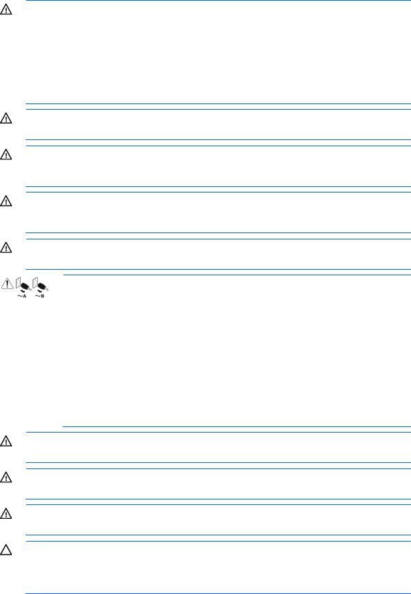
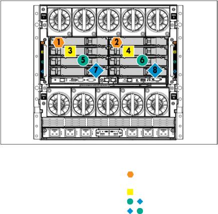
Enclosure front components
Item |
Description |
|
|
1 |
Device bays* |
|
|
2 |
Air intake slot (Do not block.) |
|
|
3 |
Power supply bay 1 |
|
|
4 |
Power supply bay 2 |
|
|
5 |
Power supply bay 3 |
|
|
6 |
Power supply bay 4 |
|
|
7 |
Insight Display |
|
|
8 |
Power supply bay 5 |
|
|
9 |
Power supply bay 6 |
|
|
10 |
Air intake slot (Do not block.) |
|
|
*For more information, see "Device bay numbering (on page 14)."
Component and LED identification 12
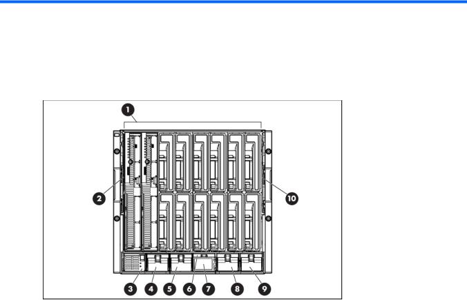
Power supply bay numbering
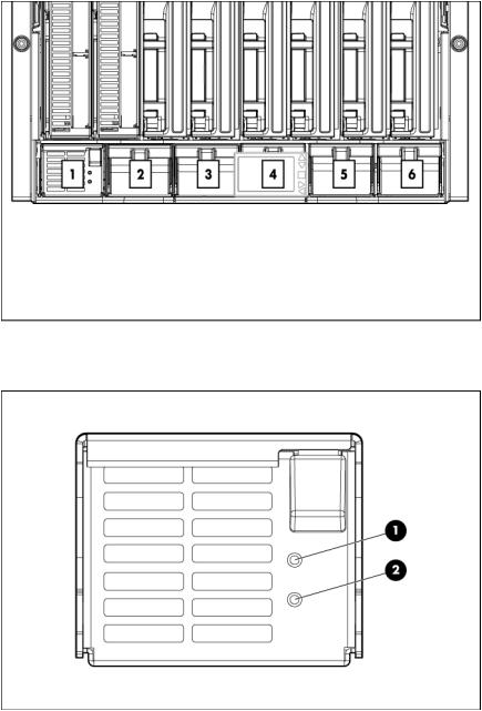
Power supply LEDs
Power LED 1 |
Fault LED 2 |
Condition |
(green) |
(amber) |
|
|
|
|
Off |
Off |
No AC power to the power supply |
On |
Off |
Normal |
Off |
On |
Power supply failure |
For power supply configuration information, see Installing a power supply (on page 29).
Component and LED identification 13
 c7000 User Manual")
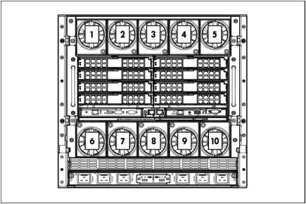
Device bay numbering
Each enclosure requires interconnects to provide network access for data transfer. Interconnects reside in bays located on the rear of the enclosure. Be sure to review device bay numbering to determine which external network connections on the interconnects are active.
IMPORTANT: When looking at the rear of the enclosure, front device bay numbering is reversed.
Full-height device bay numbering
Half-height device bay numbering
Component and LED identification 14
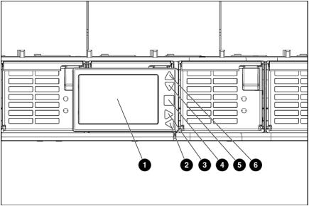
HP BladeSystem Insight Display components
Item |
Description |
Function |
|
|
|
1 |
Insight Display screen |
Displays Main Menu error messages and instructions |
2 |
Left arrow button |
Moves the menu or navigation bar selection left one position |
3 |
Right arrow button |
Moves the menu or navigation bar selection right one position |
4 |
OK button |
Accepts the highlighted selection and navigates to the selected |
|
|
menu |
|
|
|
5 |
Down arrow button |
Moves the menu selection down one position |
6 |
Up arrow button |
Moves the menu selection up one position |
|
|
|
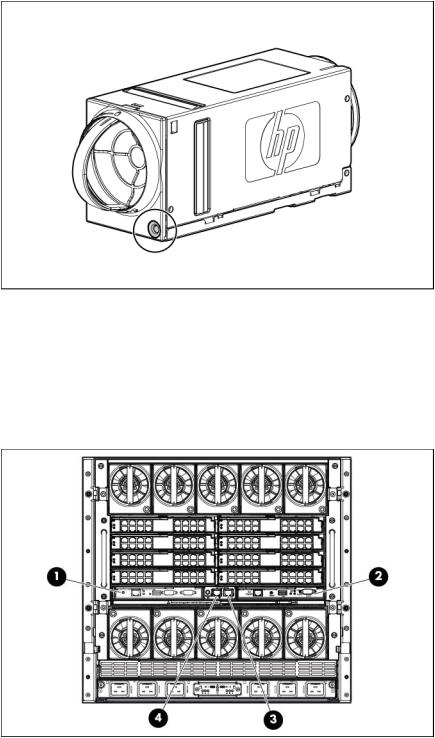
Location Discovery Services
HP provides built-in location awareness in the new ProLiant servers, a capability that works hand-in-hand with technology in the new HP Intelligent Series racks. Together these technologies provide the rack identification number and precise U location of the servers. This information is communicated through SIM, ICPM, and HP iPDUs.
For LDS software requirements, see the QuickSpecs on the HP website (http://www.hp.com/go/rackandpower).
This feature is only available on HP BladeSystem c7000 Platinum Enclosures.
Component and LED identification 15

The following figure shows the location of the contacts on the c7000 enclosure that enable use of LDS.
Enclosure rear components
Item |
Description |
|
|
1 |
Fan bay 1 |
2 |
Fan bay 2 |
3 |
Fan bay 3 |
4 |
Fan bay 4 |
5 |
Fan bay 5 |
6 |
Interconnect bay 2 |
7 |
Interconnect bay 4 |
8 |
Interconnect bay 6 |
9 |
Interconnect bay 8 |
Component and LED identification 16
Item |
Description |
|
|
10 |
Onboard Administrator bay 2 |
11 |
Power supply exhaust vent (do not block) |
12 |
Fan bay 10 |
13 |
Fan bay 9 |
14 |
Fan bay 8 |
15 |
Fan bay 7 |
16 |
Fan bay 6 |
17 |
AC power connectors |
18 |
Onboard Administrator bay 1 |
19 |
Interconnect bay 7 |
20 |
Interconnect bay 5 |
21 |
Interconnect bay 3 |
22 |
Interconnect bay 1 |
Fan bay numbering
Component and LED identification 17
Fan LED
LED color |
Fan status |
|
|
Solid green |
The fan is working. |
Solid amber |
The fan has failed. |
Flashing amber |
See the Insight Display screen. |
|
|
Onboard Administrator components
Item |
Description |
|
|
1 |
Onboard Administrator bay 1 |
2 |
Onboard Administrator bay 2 (redundant, if used) |
3 |
Enclosure link-up port |
4 |
Enclosure link-down port |
Component and LED identification 18
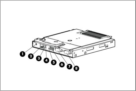
HP c7000 Onboard Administrator with KVM components
Item |
Name |
Description |
|
|
|
|
|
1 |
Reset button |
— |
|
2 |
OA/iLO management port |
Ethernet 100BaseT RJ45 |
|
|
|
connector, which |
|
|
|
provides Ethernet access |
|
|
|
to the Onboard |
|
|
|
Administrator and the |
|
|
|
iLO on each blade. Also |
|
|
|
supports interconnect |
|
|
|
modules with |
|
|
|
management processors |
|
|
|
configured to use the |
|
|
|
enclosure management |
|
|
|
network. Also supports |
|
|
|
GbE. |
|
|
|
|
|
3 |
UID LED |
Blue = UID on |
|
4 |
Active Onboard |
Indicates which |
|
|
Administrator LED |
Onboard Administrator |
|
|
|
is active |
|
|
|
|
|
5 |
Health LED |
Green = OK |
|
|
|
Red = Critical error |
|
|
|
|
|
6 |
USB |
USB 2.0 Type A |
|
|
|
connector used for |
|
|
|
connecting supported |
|
|
|
USB devices such as DVD |
|
|
|
drives, USB key drives, or |
|
|
|
a keyboard or mouse for |
|
|
|
enclosure KVM use. To |
|
|
|
connect multiple devices, |
|
|
|
a USB hub (not included) |
|
|
|
is required. |
|
|
|
|
|
|
|
Component and LED identification 19 |
|
Item |
Name |
Description |
|
|
|
7 |
Serial connector |
Serial RS232 DB-9 |
|
|
connector with PC |
|
|
standard pinout. Connect |
|
|
a computer with a |
|
|
null-modem serial cable |
|
|
to the Onboard |
|
|
Administrator command |
|
|
line interface (CLI). |
|
|
|
8 |
VGA |
VGA DB-15 connector |
|
|
with PC standard pinout. |
|
|
To access the KVM menu |
|
|
or Onboard |
|
|
Administrator CLI, |
|
|
connect a VGA monitor |
|
|
or rack KVM monitor for |
|
|
enclosure KVM. |
|
|
|
Interconnect bay numbering
To support network connections for specific signals, install the interconnect module into the appropriate bay.
Server blade signal |
Interconnect bay |
Interconnect bay label |
|
number |
|
|
|
|
NICs 1, 2, 3, and 4 |
1, 2 |
|
(embedded) |
|
|
Mezzanine 1 |
3, 4 |
|
Mezzanine 2 |
5, 6 and then 7, 8 |
|
Mezzanine 3 |
7, 8 and then 5, 6 |
|
For information on the location of LEDs and ports on individual interconnect modules, see the documentation that ships with the interconnect module.
For more information, see "Mapping to interconnect ports (on page 48)."
Component and LED identification 20
Installation
Installation overview
To set up and install the enclosure:
1.Disassemble the enclosure ("Disassembling the enclosure" on page 21).
2.For rack-free installations ("Rack-free installation" on page 24), set up the enclosure on an appropriate surface, then install the rear cage and enclosure components.
3.For rack installations, install the enclosure into the rack ("Installing the enclosure into the rack" on page 26) then reassemble the enclosure.
4.Install the enclosure components ("Component installation" on page 29) into the enclosure.
5.Connect the enclosure components ("Cabling and powering up the enclosure" on page 56) in the enclosure.
6.Connect the AC power cables and power up the enclosure ("Powering up the enclosure" on page 59).
7.Configure the enclosure ("Running the Insight Display installation steps" on page 65) using the Insight Display.
Disassembling the enclosure
Before installing the enclosure into the rack, you must disassemble the enclosure. Because a fully-populated enclosure can weigh up to 217.7 kg (480 lb), remove the components and the rear cage from the enclosure to make moving and installing the enclosure easier. Two people should work together to remove the rear cage from the enclosure.
The empty enclosure with the rear cage installed weighs 58.6 kg (129 lb). When the enclosure is disassembled, the empty enclosure without the rear cage installed weighs 35.5 kg (78 lb). The empty rear cage weighs 23.2 kg (51 lb).
Installation 21
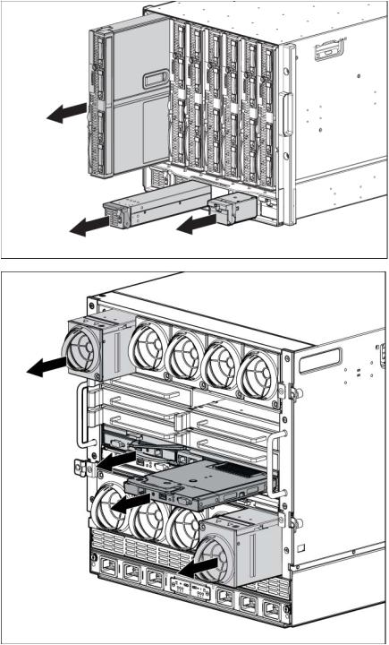
1.With the enclosure still on the pallet, remove all components from the front and rear of the enclosure.
2.Remove the rear cage:
a. Loosen the thumbscrews and open the hinges completely.
Installation 22
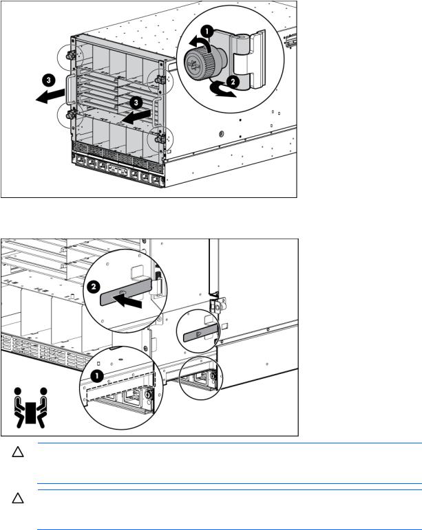
b.Use the handles to extend the rear cage until the release levers engage on both sides of the rear cage.
c.Grasp the handholds below the release levers.
d.Disengage the release levers on both sides of the rear cage.
CAUTION: When removing and lifting the rear cage, always grasp the handholds as far forward as possible. The front end of the rear cage is heavy and the handholds provide a more balanced location to distribute the weight of the cage during lifting.
CAUTION: When removing the rear cage and midplane assembly, the connectors on the midplane assembly are susceptible to damage. Use caution to avoid damage to the pins and connectors.
Installation 23
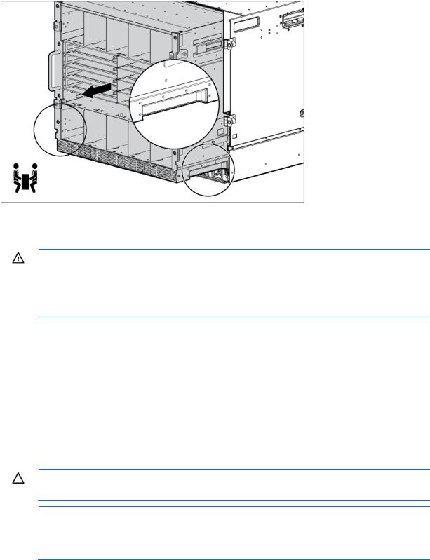
e. Use the handholds to extend and remove the rear cage from the enclosure.
Rack-free installation
WARNING: To reduce the risk of personal injury or damage to the equipment in a rack-free environment:
•Never stack the enclosure on top of another enclosure.
•Never place equipment on top of the enclosure.
•Never place the enclosure on a surface that cannot support up to 217.7 kg (480 lb).
To set up the enclosure in a rack-free environment:
1.Select the location for the enclosure. For more information, see "Rack-free environment requirements (on page 8)."
2.Disassemble the enclosure ("Disassembling the enclosure" on page 21).
3.Place the enclosure on a flat, sturdy surface to support the enclosure.
4.Install the rear cage into the enclosure. ("Installing the rear cage into the enclosure" on page 28)
Rack installation
CAUTION: Always plan the rack installation so that the heaviest item is on the bottom of the rack. Install the heaviest item first, and continue to populate the rack from the bottom to the top.
NOTE: Up to four 10U enclosures can be installed in a 42U rack. If you are installing more than one enclosure, install the first enclosure in the bottom of the rack, and then install additional enclosures by moving up the rack with each subsequent enclosure. Plan rack installation carefully because it is difficult to change the location of components after they are installed.
To install an enclosure into the rack:
1.Disassemble the enclosure ("Disassembling the enclosure" on page 21).
Installation 24
2.Use the rack template ("Measuring with the rack template" on page 25) to mark the locations for the rack rails.
3.Install the rack rails ("Installing the rack rails" on page 25) for each enclosure.
4.Install the enclosure into the rack ("Installing the enclosure into the rack" on page 26).
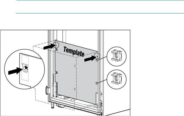
Measuring with the rack template
The rack template ships with the rack rail kit and provides detailed instructions on where to position the enclosure rack rails and where to install the four cage or clip nuts. Each enclosure kit includes the rack rails recommended for that enclosure.
NOTE: Four cage nuts and four clip nuts are included with the enclosure. Cage nuts should be used in racks with square holes. Clip nuts should be used in racks with round holes.
When installing multiple enclosures, install the rack rails and cage or clip nuts for one enclosure, and then install the enclosure. Repeat for each additional enclosure.
Installing the rack rails
The rack rails are marked for easy identification. The left rack rail is marked "L" and the right rack rail is marked "R."
To install the rack rails:
1.Begin with the left rack rail. Align the end of the rail with the rear rack column.
2.Slide the rack rail closed until the end of the rail is locked in place, wrapping behind the rear rack column.
Installation 25
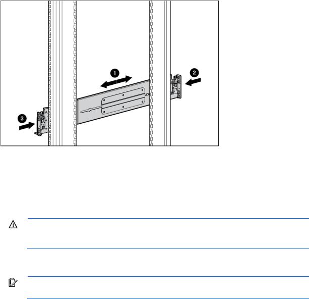
3.Slide the front end of the rail to the rack front column. When fully seated, the rack rail will lock into place.
4.Repeat the procedure for the right rack rail.
Installing the enclosure into the rack
The empty enclosure with the rear cage installed weighs 58.6 kg (129 lb). When the enclosure is disassembled, the empty enclosure without the rear cage installed weighs 35.5 kg (78 lb). The empty rear cage weighs 23.2 kg (51 lb).
WARNING: Always use at least two people to lift an enclosure into the rack. If the enclosure is being loaded into the rack above chest level, a third person must assist with aligning the enclosure with the rails while the other two people support the weight of the enclosure.
To install the enclosure into the rack:
1.At the front of the rack, lift and align the enclosure guiding fins with the guiding groove in the rack rails.
IMPORTANT: Be sure that the guiding fins on the enclosure seat properly in the guiding groove on the rack rail.
Installation 26
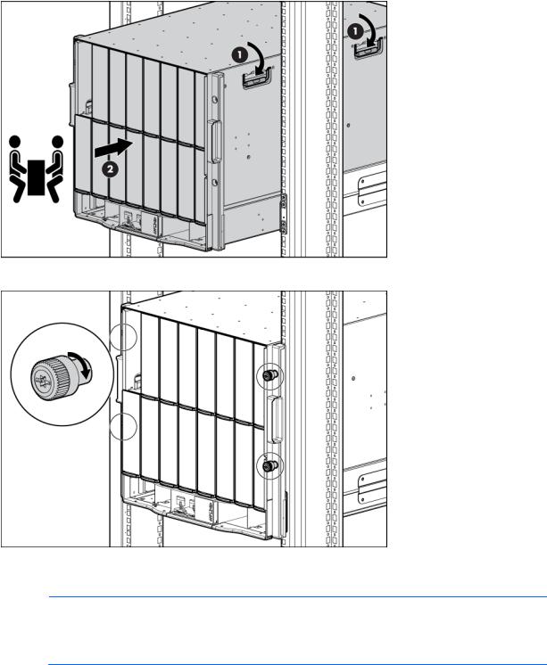
2.Push the handles down on each side of the enclosure, and slide the enclosure fully into the rack.
3.Tighten the thumbscrews to secure the enclosure to the rack.
4.Install the rear cage into the enclosure. ("Installing the rear cage into the enclosure" on page 28)
5.Repeat the procedure for the remaining enclosures.
NOTE: Up to four 10U enclosures can be installed in a 42U rack. If you are installing more than one enclosure, install the first enclosure in the bottom of the rack, and then install additional enclosures by moving up the rack with each subsequent enclosure. Plan rack installation carefully because it is difficult to change the location of components after they are installed.
Installation 27

Installing the rear cage into the enclosure
1.Open all hinges completely.
2.Position the rear cage at the rear of the enclosure, and align the rear cage guiding fins with the guiding groove in the rack rails.
3.Slide the rear cage fully into the enclosure.
CAUTION: Do not touch or bump rear cage connector pins when installing the rear cage into the enclosure.
Installation 28

4.Close the hinges, and tighten the thumbscrews to secure the rear cage.
Component installation
The following sections contain installation instructions for the individual enclosure components. All components must be installed and cabled before you power up the enclosure. There is no specific installation order requirement for the enclosure components.
Installing a power supply
See "Running the Insight Display installation steps (on page 65)" for information on the types of power configurations available and how to set them up.
If your HP BladeSystem c7000 Enclosure is equipped with a three-phase power configuration, six power supplies are required. Single-phase configurations can have fewer than six power supplies.
Install the power supplies based on the total number of supplies needed:
•Two power supplies: Bays 1 and 4
•Three power supplies: Bays 1, 2, and 4
•Four power supplies: Bays 1, 2, 4, and 5
•Five power supplies: Bays 1, 2, 3, 4, and 5
•Six power supplies: All bays
Install power supply blanks in any unused power supply bays.
Power supplies are installed in this manner to provide maximum flexibility for redundancy in three-phase configuration options.
CAUTION: Do not mix HP 2250W, HP 2400W High Efficiency, HP BL7000 2400W Platinum, or -48vDC power supplies in one enclosure. Install only one type of power supply in a single enclosure.
Installation 29
NOTE: This document discusses installation of AC power supplies only. For information on configuring DC power supplies or HP Carrier Grade Solutions, see the documentation that came with your power supply.
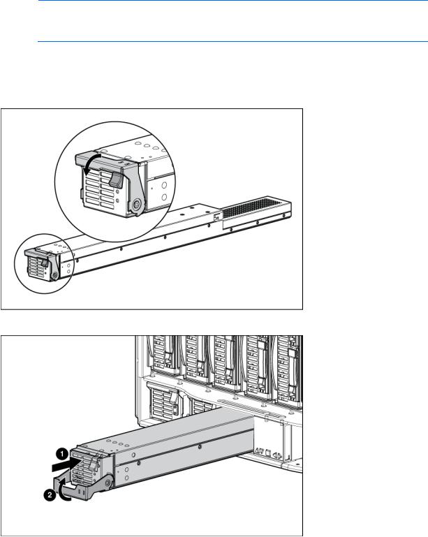
To install a power supply:
1.Slide the HP BladeSystem Insight Display to the right or left to gain access to all power supply bays.
2.Open the power supply bracket.
3.Insert the power supply into the enclosure, and then close the bracket.
Check the power supply LEDs (on page 13) to determine the status of the power supply.
To calculate how many power supplies are needed, see the HP BladeSystem Power Sizer (http://www.hp.com/go/bladesystem/powercalculator).
Installation 30
Loading...