


 Loading...
Cut Sheet Printers
Maintenance Manual
Models C30 and C30D
HP Part No. C4000-90006

Notice
Hewlett-Packard makes no warranty of any kind with regard to this material, including, but not limited to, the implied warranties of merchantability and fitness for a particular purpose. Hewlett-Packard shall not be liable for errors contained herein or for incidental or consequential damages in connection with the furnishing, performance, or use of this material.
Hewlett-Packard assumes no responsibility for the use or reliability of its software on equipment that is not furnished by Hewlett-Packard.
This document contains proprietary information which is protected by copyright. All rights are reserved. No part of this document may be photocopied, reproduced, or translated to another language without the prior written consent of Hewlett-Packard Company. The information contained in this document is subject to change without notice.
Printing History
New editions are complete revisions of the manual. The dates on the title page change only when a new edition is published.
The software code (EXXX) printed below the date indicates the version level of the software product at the time of publication.
Edition 1 . . . . . . . . . . . . . . . . . . . . . . . . . . .March 1994
Edition 2. . . . . . . . . . . . . . . . . . . . . . . . . . .December 1994
Trademarks
PCL is a trademark of the Hewlett-Packard Company. CG Times, a product of Agfa Corporation, is based on Times New Roman, a registered trademark of Monotype Corporation PLC. ITC Zapf Dingbats is a U.S. registered trademark of International Typeface Corporation. PostScript is a registered trademark of Adobe Systems, Inc. in the U.S.A. and other countries. Times Roman and Univers are trademarks of Linotype AG and its subsidiaries. Centronics is a U.S. registered trademark of Centronics Corporation. PhoenixPage is a trademark of Phoenix technologies, Ltd. UNIX is a registered trademark of UNIX System Laboratories Inc. in the U.S.A. and other countries. DEC LN03+ is a registered trademark of Digital Equipment Corporation. All other trademarks are the properties of their respective owners.
-ii

Warnings and Cautions
A WARNING denotes a hazard. It calls attention to a procedure or practice, which, if not done correctly or adhered to, could result in personal injury. Do not proceed beyond a WARNING sign until the indicated conditions are fully understood and met.
A CAUTION denotes a hazard. It calls attention to a procedure which, if done incorrectly or inattentively, could damage or destroy part or all of the product. Do not proceed beyond a CAUTION until the indicated conditions are fully understood and met.
Conventions
The following conventions are used throughout this manual:
Note
Notes contain important information set off from the text.
Caution
Caution messages indicate procedures which, if not observed, could result in damage to the equipment.
Warning
Warning messages call attention to situations that could result in personal injury.
-iii

Preface
The C30/C30D Maintenance Manual contains all the information needed to maintain and service Hewlett Packard C30 and C30D printers. The C30 printer series are high-speed, non-impact printers utilizing electrophotographic imaging technology.
The information in this maintenance manual is for authorized field representatives who are familiar with basic printer operations. It serves as a supplement to training classes and provides a basis for discussion with regional field service engineers and customer support representatives.
Using This Manual
This manual is organized into the following sections:
Chapter 1, “Printer and Troubleshooting Overview”
Reviews the organization of the manual, the way the printer works, and how to troubleshoot the printer, including some standard procedures to follow when troubleshooting. This chapter also includes a chart detailing exactly what each causes each error code, illustrations of all sensors in the printer, and a list of abbreviations used throughout the manual.
Chapter 2, “TAG CrossReference Tables”
Provides cross-reference tables; look up specific printer problem description (in either the mechanical malfunction, error code, or print quality description tables), then turn to the TAG indicated on the chart to troubleshoot the problem.
Chapter 3, “Troubleshooting Analysis Guide (TAGs)”
Detailed step-by-step procedures to help you isolate and resolve specific printer problems. If you are not sure which TAG to start with, begin with the overview, TAG 001.
Chapter 4, “Print Quality Samples”
Shows print test patterns indicating specific problems, and referencing the TAG that treats each problem.
Chapter 5, “Diagnostic Tests”
Reviews each printer software diagnostic.
Chapter 6, “Wiring Diagrams and Electrical Data”
Shows printer schematics and locations of individual components.
Chapter 7, “Removal/Replacement Procedures”
Outlines procedures to follow when removing and replacing printer parts, also called FRUs (Field-Replaceable Units).
-iv
Chapter 8, “Options”
Provides information about the optional High Capacity Input and High Capacity Output bins.
Chapter 9, “General Printer Maintenance”
Reviews printer maintenance procedures to complete during service calls.
Appendix A
Lists the abbreviations and acronyms used in the manual.
Index
Provides a list of references to topics and part numbers mentioned in the Maintenance Manual
Other Manuals
The C-Series Illustrated Parts Catalog shows every FRU and CRU (customer-replaceable unit) in the printer, including part number information. This information is frequently updated.
The HP C30 and C30D Guide to Operations, C4000-96006, contains all the information needed to operate Hewlett Packard C40D printers.
The HP C30 and C40D Paper Specifications Guide, C4672-90002, explains the various kinds of papers usable in the printer, how to care for them, and how to minimize paperrelated problems with the C40D.
Copyright © 1995 Hewlett-Packard Company. All rights reserved. January 1995
Please address any comments or questions with respect to this document to:
Publication Department
Hewlett-Packard Company
HP Printers - MS 44MC
System Peripherals Operation
19111 Pruneridge Avenue
Cupertino, CA 95014
-v
-vi

Contents
Printer and Troubleshooting Overview
Contents . . . . . . . . . . . . . . . . . . . . . . . . . . . . . . . . . . . . . . . . . . . . . . . . . . . . . . . . . . 1-2 Theory of Operation . . . . . . . . . . . . . . . . . . . . . . . . . . . . . . . . . . . . . . . . . . . . . . . . . 1-3 Paper Path and Cycle Sequence . . . . . . . . . . . . . . . . . . . . . . . . . . . . . . . . . . . . . . . . 1-5
Simplex Printing . . . . . . . . . . . . . . . . . . . . . . . . . . . . . . . . . . . . . . . . . . . . . . . . . . . . . . . 1-5 Duplex Printing . . . . . . . . . . . . . . . . . . . . . . . . . . . . . . . . . . . . . . . . . . . . . . . . . . . . . . . 1-5
Error Code Technical Definitions. . . . . . . . . . . . . . . . . . . . . . . . . . . . . . . . . . . . . . . 1-7 Sensor and Switch Locations . . . . . . . . . . . . . . . . . . . . . . . . . . . . . . . . . . . . . . . . . 1-11 Troubleshooting Overview . . . . . . . . . . . . . . . . . . . . . . . . . . . . . . . . . . . . . . . . . . . 1-15
General Troubleshooting Tips . . . . . . . . . . . . . . . . . . . . . . . . . . . . . . . . . . . . . . . . . . . 1-15 The Problem: Printer or Host? . . . . . . . . . . . . . . . . . . . . . . . . . . . . . . . . . . . . . . . . . . . 1-16 Protocol Converters . . . . . . . . . . . . . . . . . . . . . . . . . . . . . . . . . . . . . . . . . . . . . . . . . . . 1-17 Reading the Error Log . . . . . . . . . . . . . . . . . . . . . . . . . . . . . . . . . . . . . . . . . . . . . . . . . 1-17 Confirming Line Power . . . . . . . . . . . . . . . . . . . . . . . . . . . . . . . . . . . . . . . . . . . . . . . . 1-18
Using the Troubleshooting Analysis Guide (TAG) . . . . . . . . . . . . . . . . . . . . . . . . 1-19
Sample TAG . . . . . . . . . . . . . . . . . . . . . . . . . . . . . . . . . . . . . . . . . . . . . . . . . . . . . . . . . 1-19
Standard Procedures . . . . . . . . . . . . . . . . . . . . . . . . . . . . . . . . . . . . . . . . . . . . . . . . 1-21
Power-on-reset (POR) . . . . . . . . . . . . . . . . . . . . . . . . . . . . . . . . . . . . . . . . . . . . . . . . . 1-21
Checking Continuity. . . . . . . . . . . . . . . . . . . . . . . . . . . . . . . . . . . . . . . . . . . . . . . . . . . 1-21
Installing the Interlock By-pass Tool . . . . . . . . . . . . . . . . . . . . . . . . . . . . . . . . . . . . . . 1-22
Producing a Developed Image . . . . . . . . . . . . . . . . . . . . . . . . . . . . . . . . . . . . . . . . . . . 1-22
Producing a Toner Patch . . . . . . . . . . . . . . . . . . . . . . . . . . . . . . . . . . . . . . . . . . . . . . . 1-22
Completing a Service Call . . . . . . . . . . . . . . . . . . . . . . . . . . . . . . . . . . . . . . . . . . . . . . 1-23
Clearing the Error Log . . . . . . . . . . . . . . . . . . . . . . . . . . . . . . . . . . . . . . . . . . . . . . . . . 1-24
TAG Cross-Reference Tables
TAG Cross-Reference Tables . . . . . . . . . . . . . . . . . . . . . . . . . . . . . . . . . . . . . . . . . 2-2
Error Code/TAG Cross-Reference . . . . . . . . . . . . . . . . . . . . . . . . . . . . . . . . . . . . . . 2-3
Print Quality/TAG Cross-Reference . . . . . . . . . . . . . . . . . . . . . . . . . . . . . . . . . . . . 2-9
Mechanical Malfunction/TAG Cross-Reference . . . . . . . . . . . . . . . . . . . . . . . . . . 2-12
Troubleshooting Analysis Guide (TAGs)
Contents . . . . . . . . . . . . . . . . . . . . . . . . . . . . . . . . . . . . . . . . . . . . . . . . . . . . . . . . . . 3-2
Troubleshooting Analysis Guide (TAGs) . . . . . . . . . . . . . . . . . . . . . . . . . . . . . . . . . 3-4
TAG 001: Troubleshooting a Problem . . . . . . . . . . . . . . . . . . . . . . . . . . . . . . . . . . . . . . 3-5
TAG 002: Check & Problem Resolution . . . . . . . . . . . . . . . . . . . . . . . . . . . . . . . . . . . . 3-8
TAG 010: Upper Cassette Malfunction . . . . . . . . . . . . . . . . . . . . . . . . . . . . . . . . . . . . 3-12
E10: Envelope Tray Out of Envelopes . . . . . . . . . . . . . . . . . . . . . . . . . . . . . . . . . . . . . 3-14
TAG 011: Lower Cassette Malfunction . . . . . . . . . . . . . . . . . . . . . . . . . . . . . . . . . . . . 3-16
vii
TAG 012: Upper Cassette Not Latched . . . . . . . . . . . . . . . . . . . . . . . . . . . . . . . . . . . . 3-18 TAG E12: Envelope Tray or Feeder Not Latched . . . . . . . . . . . . . . . . . . . . . . . . . . . . 3-21 TAG 013: Lower Cassette Not Latched . . . . . . . . . . . . . . . . . . . . . . . . . . . . . . . . . . . . 3-24 TAG 020: Paper Jam/Misfeed in Upper Cassette Area . . . . . . . . . . . . . . . . . . . . . . . . 3-26 TAG 021: Paper Jam/Misfeed in /Lower Cassette Area. . . . . . . . . . . . . . . . . . . . . . . . 3-30 TAG 022: Paper Jam in the Transfer or Fuser Area . . . . . . . . . . . . . . . . . . . . . . . . . . . 3-34 TAG 023: Paper Jam in the Output Area . . . . . . . . . . . . . . . . . . . . . . . . . . . . . . . . . . . 3-39 TAG 025: Paper in Input Area Before Printing . . . . . . . . . . . . . . . . . . . . . . . . . . . . . . 3-41 TAG 026: Paper in Output Area Before Printing . . . . . . . . . . . . . . . . . . . . . . . . . . . . . 3-43 TAG 030: Developer Bias Short/Failure . . . . . . . . . . . . . . . . . . . . . . . . . . . . . . . . . . . 3-44 TAG 031: Toner Patch Reference Level Too Low. . . . . . . . . . . . . . . . . . . . . . . . . . . . 3-47 TAG 032: Toner Patch Too Light. . . . . . . . . . . . . . . . . . . . . . . . . . . . . . . . . . . . . . . . . 3-49 TAG 035: Out of Toner or ADD TONER Indicator On. . . . . . . . . . . . . . . . . . . . . . . . 3-51 TAG 036: Developer Unit Not Installed. . . . . . . . . . . . . . . . . . . . . . . . . . . . . . . . . . . . 3-53 TAG 040: Photoconductor Seam Sensor Malfunction . . . . . . . . . . . . . . . . . . . . . . . . . 3-54 TAG 044: Main Charger/Transfer Charger Circuit Open. . . . . . . . . . . . . . . . . . . . . . . 3-58 TAG 045: Main Charger Circuit Shorted . . . . . . . . . . . . . . . . . . . . . . . . . . . . . . . . . . . 3-61 TAG 050: Transfer Charger Circuit Shorted . . . . . . . . . . . . . . . . . . . . . . . . . . . . . . . . 3-63 TAG 055: Erase Lamp Malfunction . . . . . . . . . . . . . . . . . . . . . . . . . . . . . . . . . . . . . . . 3-65 TAG 070: Fuser Unit Malfunction . . . . . . . . . . . . . . . . . . . . . . . . . . . . . . . . . . . . . . . . 3-67 TAG 071: Open Fuser Thermistor . . . . . . . . . . . . . . . . . . . . . . . . . . . . . . . . . . . . . . . . 3-72 TAG 072: Fuser Unit Temperature Too High . . . . . . . . . . . . . . . . . . . . . . . . . . . . . . . 3-73 TAG 083: Job Offset Mechanism Malfunction . . . . . . . . . . . . . . . . . . . . . . . . . . . . . . 3-75 TAG 097: +12 Vdc Power Shorted or Sensing Problem . . . . . . . . . . . . . . . . . . . . . . . 3-79 TAG 098: -12 Vdc Power Shorted . . . . . . . . . . . . . . . . . . . . . . . . . . . . . . . . . . . . . . . . 3-90 TAG 099: +24 Vdc Power Shorted. . . . . . . . . . . . . . . . . . . . . . . . . . . . . . . . . . . . . . . . 3-92 TAG 100: PCL Board Interface Malfunction . . . . . . . . . . . . . . . . . . . . . . . . . . . . . . . 3-102 TAG 101: IGS Controller Diagnostic Failure. . . . . . . . . . . . . . . . . . . . . . . . . . . . . . . 3-103 TAG 130: Diskette/Disk Drive Malfunction . . . . . . . . . . . . . . . . . . . . . . . . . . . . . . . 3-104 TAG 200: IGS Internal Communication Malfunction . . . . . . . . . . . . . . . . . . . . . . . . 3-108 TAG 201: IGS-PCL Interface Malfunction . . . . . . . . . . . . . . . . . . . . . . . . . . . . . . . . 3-110 TAG 405: IGS Bit-Map RAM Malfunction . . . . . . . . . . . . . . . . . . . . . . . . . . . . . . . . 3-112 TAG 500: +5 Vdc Power Malfunction . . . . . . . . . . . . . . . . . . . . . . . . . . . . . . . . . . . . 3-113 TAG 600: AC Power Malfunction . . . . . . . . . . . . . . . . . . . . . . . . . . . . . . . . . . . . . . . 3-118 TAG 610: Operator Panel Malfunction . . . . . . . . . . . . . . . . . . . . . . . . . . . . . . . . . . . 3-125 TAG 700: Output Tray Circuit Malfunction. . . . . . . . . . . . . . . . . . . . . . . . . . . . . . . . 3-130 TAG 702: Paper Size Detection Malfunction . . . . . . . . . . . . . . . . . . . . . . . . . . . . . . . 3-132 TAG 703: Upper Cassette Malfunction . . . . . . . . . . . . . . . . . . . . . . . . . . . . . . . . . . . 3-135 TAG 704: Lower Cassette Malfunction . . . . . . . . . . . . . . . . . . . . . . . . . . . . . . . . . . . 3-136 TAG 705: Multiple Paper Feeding . . . . . . . . . . . . . . . . . . . . . . . . . . . . . . . . . . . . . . . 3-137 TAG 706: Paper Damaged or Wrinkled . . . . . . . . . . . . . . . . . . . . . . . . . . . . . . . . . . . 3-138 TAG 707: Upper Paper Guide Assembly Not Closing . . . . . . . . . . . . . . . . . . . . . . . . 3-139 TAG 750: Counter Malfunction . . . . . . . . . . . . . . . . . . . . . . . . . . . . . . . . . . . . . . . . . 3-140 TAG 751: Main Drive Motor Runs Continuously . . . . . . . . . . . . . . . . . . . . . . . . . . . 3-142 TAG 753: External Communications Malfunction. . . . . . . . . . . . . . . . . . . . . . . . . . . 3-143 TAG 754: Attachment Option Malfunction . . . . . . . . . . . . . . . . . . . . . . . . . . . . . . . . 3-146 TAG 800: Prints Blank or With Dark Horizontal Bands . . . . . . . . . . . . . . . . . . . . . . 3-148 TAG 801: Prints Light or Light With Carrier Particles . . . . . . . . . . . . . . . . . . . . . . . 3-152 TAG 802: Prints With Voids or White Spots . . . . . . . . . . . . . . . . . . . . . . . . . . . . . . . 3-158 TAG 803: Prints With Light or White Vertical Streaks . . . . . . . . . . . . . . . . . . . . . . . 3-160
viii

TAG 804: Prints With Light Horizontal Bands . . . . . . . . . . . . . . . . . . . . . . . . . . . . . 3-162 TAG 805: Black Prints . . . . . . . . . . . . . . . . . . . . . . . . . . . . . . . . . . . . . . . . . . . . . . . . 3-163 TAG 806: Prints with Dark Spots or Scratches . . . . . . . . . . . . . . . . . . . . . . . . . . . . . 3-166 TAG 807: Misregistered/Skewed Prints (Simplex) . . . . . . . . . . . . . . . . . . . . . . . . . . 3-168 TAG 808: Prints Overtoned/Dark Vertical Streaks . . . . . . . . . . . . . . . . . . . . . . . . . . 3-172 TAG 809: Blurred or Smeared Vertical Streaks on Prints . . . . . . . . . . . . . . . . . . . . . 3-177 TAG 810: Uneven Density or Dark Areas on Prints . . . . . . . . . . . . . . . . . . . . . . . . . 3-180 TAG 811: Background/Residual Images/Dark Prints . . . . . . . . . . . . . . . . . . . . . . . . 3-182 TAG 812: Uneven or No Fusing on Prints . . . . . . . . . . . . . . . . . . . . . . . . . . . . . . . . . 3-187 TAG 813: Residual Images on Prints. . . . . . . . . . . . . . . . . . . . . . . . . . . . . . . . . . . . . 3-189 TAG 815: Prints Resulting From Printhead Malfunctions. . . . . . . . . . . . . . . . . . . . . 3-191 TAG 900: Top Cover Interlock Malfunction, Duplex . . . . . . . . . . . . . . . . . . . . . . . . 3-192 TAG 901: Misregistration/Skewed Prints (Duplex). . . . . . . . . . . . . . . . . . . . . . . . . . 3-194 TAG 902: Paper Jam in Duplex Area. . . . . . . . . . . . . . . . . . . . . . . . . . . . . . . . . . . . . 3-198
Print Quality Samples
Contents . . . . . . . . . . . . . . . . . . . . . . . . . . . . . . . . . . . . . . . . . . . . . . . . . . . . . . . . . . 4-2 Print Quality Samples . . . . . . . . . . . . . . . . . . . . . . . . . . . . . . . . . . . . . . . . . . . . . . . . 4-3 Sample 1: Good Quality Print. . . . . . . . . . . . . . . . . . . . . . . . . . . . . . . . . . . . . . . . . . 4-4 Sample 2: Washout . . . . . . . . . . . . . . . . . . . . . . . . . . . . . . . . . . . . . . . . . . . . . . . . . . 4-5 Sample 3: Blank Print . . . . . . . . . . . . . . . . . . . . . . . . . . . . . . . . . . . . . . . . . . . . . . . . 4-6 Sample 4: Light Print . . . . . . . . . . . . . . . . . . . . . . . . . . . . . . . . . . . . . . . . . . . . . . . . 4-7 Sample 5: Light Print With Background . . . . . . . . . . . . . . . . . . . . . . . . . . . . . . . . . 4-8 Sample 6: Voids or White Spots. . . . . . . . . . . . . . . . . . . . . . . . . . . . . . . . . . . . . . . . 4-9 Sample 7: Light Vertical Streaks . . . . . . . . . . . . . . . . . . . . . . . . . . . . . . . . . . . . . . 4-10 Sample 8: Blank Vertical Bands . . . . . . . . . . . . . . . . . . . . . . . . . . . . . . . . . . . . . . . 4-11 Sample 9: Light Horizontal Bands . . . . . . . . . . . . . . . . . . . . . . . . . . . . . . . . . . . . . 4-12 Sample 10: Black or Dark Print . . . . . . . . . . . . . . . . . . . . . . . . . . . . . . . . . . . . . . . 4-13 Sample 11: Dark Specks, Lines, or Areas . . . . . . . . . . . . . . . . . . . . . . . . . . . . . . . 4-14 Sample 12: Dark Vertical Lines . . . . . . . . . . . . . . . . . . . . . . . . . . . . . . . . . . . . . . . 4-15 Sample 13: Skewed Prints . . . . . . . . . . . . . . . . . . . . . . . . . . . . . . . . . . . . . . . . . . . 4-16 Sample 14: Misregistration . . . . . . . . . . . . . . . . . . . . . . . . . . . . . . . . . . . . . . . . . . . 4-17 Sample 15: Overtoned Print . . . . . . . . . . . . . . . . . . . . . . . . . . . . . . . . . . . . . . . . . . 4-18 Sample 16: Blurred Images or Characters . . . . . . . . . . . . . . . . . . . . . . . . . . . . . . . 4-19 Sample 17: Varying Print Density . . . . . . . . . . . . . . . . . . . . . . . . . . . . . . . . . . . . . 4-20 Sample 18: Background . . . . . . . . . . . . . . . . . . . . . . . . . . . . . . . . . . . . . . . . . . . . . 4-21 Sample 19: Residual Images. . . . . . . . . . . . . . . . . . . . . . . . . . . . . . . . . . . . . . . . . . 4-22 Sample 20: Wrinkles. . . . . . . . . . . . . . . . . . . . . . . . . . . . . . . . . . . . . . . . . . . . . . . . 4-23 Sample 21: Fusing Problems . . . . . . . . . . . . . . . . . . . . . . . . . . . . . . . . . . . . . . . . . 4-24
Diagnostic Tests
Contents . . . . . . . . . . . . . . . . . . . . . . . . . . . . . . . . . . . . . . . . . . . . . . . . . . . . . . . . . . 5-2 Diagnostic Tests . . . . . . . . . . . . . . . . . . . . . . . . . . . . . . . . . . . . . . . . . . . . . . . . . . . . 5-3 How to Run Diagnostics . . . . . . . . . . . . . . . . . . . . . . . . . . . . . . . . . . . . . . . . . . . . . 5-3
ix

001 Operator Panel Test . . . . . . . . . . . . . . . . . . . . . . . . . . . . . . . . . . . . . . . . . . . . . . 5-4 002 Upper Cassette Test . . . . . . . . . . . . . . . . . . . . . . . . . . . . . . . . . . . . . . . . . . . . . . 5-4 003 Lower Cassette Test. . . . . . . . . . . . . . . . . . . . . . . . . . . . . . . . . . . . . . . . . . . . . . 5-5 005 Sensor Test Sequence . . . . . . . . . . . . . . . . . . . . . . . . . . . . . . . . . . . . . . . . . . . . 5-6 006 Paper Transport Clutch Test Sequence . . . . . . . . . . . . . . . . . . . . . . . . . . . . . . . 5-7 007 Counter Test. . . . . . . . . . . . . . . . . . . . . . . . . . . . . . . . . . . . . . . . . . . . . . . . . . . . 5-7 008 Jogging Motor Test . . . . . . . . . . . . . . . . . . . . . . . . . . . . . . . . . . . . . . . . . . . . . . 5-8 009 Photoconductor Test . . . . . . . . . . . . . . . . . . . . . . . . . . . . . . . . . . . . . . . . . . . . . 5-8 010 Toner Supply Motor Test. . . . . . . . . . . . . . . . . . . . . . . . . . . . . . . . . . . . . . . . . . 5-9 011 Main Charger Test . . . . . . . . . . . . . . . . . . . . . . . . . . . . . . . . . . . . . . . . . . . . . . 5-10 012 Transfer Charger Test . . . . . . . . . . . . . . . . . . . . . . . . . . . . . . . . . . . . . . . . . . . 5-11 013 Erase Lamp Test . . . . . . . . . . . . . . . . . . . . . . . . . . . . . . . . . . . . . . . . . . . . . . . 5-12 015 Negative Developer Bias Test . . . . . . . . . . . . . . . . . . . . . . . . . . . . . . . . . . . . . 5-13 016 Duplex Feed Motor Test . . . . . . . . . . . . . . . . . . . . . . . . . . . . . . . . . . . . . . . . . 5-14 017 Duplex Input Sensor Test Sequence . . . . . . . . . . . . . . . . . . . . . . . . . . . . . . . . 5-15 018 Duplex Clutch Test Sequence . . . . . . . . . . . . . . . . . . . . . . . . . . . . . . . . . . . . . 5-16 019 Duplex Tray Paper-Guide Motor Test . . . . . . . . . . . . . . . . . . . . . . . . . . . . . . . 5-17 020 High-Capacity Output Unit Test . . . . . . . . . . . . . . . . . . . . . . . . . . . . . . . . . . . 5-18 021 High-Capacity Input Unit Test . . . . . . . . . . . . . . . . . . . . . . . . . . . . . . . . . . . . 5-19 022 Envelope Fuser Solenoid Test . . . . . . . . . . . . . . . . . . . . . . . . . . . . . . . . . . . . . 5-19 101 EIGS/MIGS Board Test. . . . . . . . . . . . . . . . . . . . . . . . . . . . . . . . . . . . . . . . . . 5-20 102 EIGS/MIGS Board Test (Continuous Loop) . . . . . . . . . . . . . . . . . . . . . . . . . . 5-20 103 Communication Loop-back Test (Single Loop) . . . . . . . . . . . . . . . . . . . . . . . 5-21 104 Communication Loop-back Test (Continuous Loop) . . . . . . . . . . . . . . . . . . . 5-22 105 EIGS Program RAM Test (Continuous Loop) . . . . . . . . . . . . . . . . . . . . . . . . 5-22 107 EIGS/MIGS Bit Map Test (Single Loop) . . . . . . . . . . . . . . . . . . . . . . . . . . . . 5-23 108 EIGS/MIGS Bit Map Test (Continuous Loop) . . . . . . . . . . . . . . . . . . . . . . . . 5-23 110Format Disk/Clear Error Log . . . . . . . . . . . . . . . . . . . . . . . . . . . . . . . . . . . . . . 5-24 111 LED Printhead Test . . . . . . . . . . . . . . . . . . . . . . . . . . . . . . . . . . . . . . . . . . . . . 5-24 112 Disk Drive Test (Single Loop With Stop on Error). . . . . . . . . . . . . . . . . . . . . 5-25 113 Disk Drive Test (Continuous Loop) . . . . . . . . . . . . . . . . . . . . . . . . . . . . . . . . 5-26
Wiring Diagrams and Electrical Data
Contents . . . . . . . . . . . . . . . . . . . . . . . . . . . . . . . . . . . . . . . . . . . . . . . . . . . . . . . . . . 6-2 Wiring Diagrams and Electrical Data . . . . . . . . . . . . . . . . . . . . . . . . . . . . . . . . . . . . 6-3 Connector (J/P) Index . . . . . . . . . . . . . . . . . . . . . . . . . . . . . . . . . . . . . . . . . . . . . . . . 6-4 Connector Locations . . . . . . . . . . . . . . . . . . . . . . . . . . . . . . . . . . . . . . . . . . . . . . . . . 6-6
Connectors Inside the Front Cover . . . . . . . . . . . . . . . . . . . . . . . . . . . . . . . . . . . . . . . . . 6-6 Connectors Inside the Left Cover . . . . . . . . . . . . . . . . . . . . . . . . . . . . . . . . . . . . . . . . . . 6-7 Connectors on the Duplex Cover . . . . . . . . . . . . . . . . . . . . . . . . . . . . . . . . . . . . . . . . . . 6-8 Connectors Inside the Right Cover . . . . . . . . . . . . . . . . . . . . . . . . . . . . . . . . . . . . . . . . . 6-9 Connectors Inside the Top Cover . . . . . . . . . . . . . . . . . . . . . . . . . . . . . . . . . . . . . . . . . 6-10 Connectors on the Back Cover . . . . . . . . . . . . . . . . . . . . . . . . . . . . . . . . . . . . . . . . . . . 6-11 Connectors Inside the Back Cover (J/P2-14) . . . . . . . . . . . . . . . . . . . . . . . . . . . . . . . . 6-12
x
Connectors Inside the Back Cover (Continued) J/P18-62 . . . . . . . . . . . . . . . . . . . . . . 6-13 Connectors Inside the Back Cover (Continued) J/P 64-85. . . . . . . . . . . . . . . . . . . . . . 6-14 Connectors Inside the Back Cover (Continued) J/P 90-800. . . . . . . . . . . . . . . . . . . . . 6-15
Voltage Isolation Diagrams . . . . . . . . . . . . . . . . . . . . . . . . . . . . . . . . . . . . . . . . . . 6-16 Ground System . . . . . . . . . . . . . . . . . . . . . . . . . . . . . . . . . . . . . . . . . . . . . . . . . . . . 6-21 Host Interface Reference . . . . . . . . . . . . . . . . . . . . . . . . . . . . . . . . . . . . . . . . . . . . 6-22
RS-232C Host Interface . . . . . . . . . . . . . . . . . . . . . . . . . . . . . . . . . . . . . . . . . . . . . . . . 6-22 Standard DCE to DTE RS-232C Cable . . . . . . . . . . . . . . . . . . . . . . . . . . . . . . . . . . . . 6-23 Special Considerations for RS-232 Host Interface Users. . . . . . . . . . . . . . . . . . . . . . . 6-23 DTE Host to Printer (Option 1) . . . . . . . . . . . . . . . . . . . . . . . . . . . . . . . . . . . . . . . . . . 6-24 DTE Host to Printer (Option 2) . . . . . . . . . . . . . . . . . . . . . . . . . . . . . . . . . . . . . . . . . . 6-24 IBM PC/XT to Printer . . . . . . . . . . . . . . . . . . . . . . . . . . . . . . . . . . . . . . . . . . . . . . . . . 6-25 IBM PC/AT to Printer . . . . . . . . . . . . . . . . . . . . . . . . . . . . . . . . . . . . . . . . . . . . . . . . . 6-25 Macintosh Communication Port to Printer. . . . . . . . . . . . . . . . . . . . . . . . . . . . . . . . . . 6-26 RS-422 Host interface . . . . . . . . . . . . . . . . . . . . . . . . . . . . . . . . . . . . . . . . . . . . . . . . . 6-26 Centronics Parallel Host Interface . . . . . . . . . . . . . . . . . . . . . . . . . . . . . . . . . . . . . . . . 6-27 IBM Parallel to Printer . . . . . . . . . . . . . . . . . . . . . . . . . . . . . . . . . . . . . . . . . . . . . . . . . 6-28 Special Considerations for Centronics Parallel Interface Users. . . . . . . . . . . . . . . . . . 6-29
Circuit Board Settings. . . . . . . . . . . . . . . . . . . . . . . . . . . . . . . . . . . . . . . . . . . . . . . 6-30
Signal Interface Board Settings . . . . . . . . . . . . . . . . . . . . . . . . . . . . . . . . . . . . . . . . . . 6-30
PCL Board Settings . . . . . . . . . . . . . . . . . . . . . . . . . . . . . . . . . . . . . . . . . . . . . . . . . . . 6-31
Printhead Circuit Board Settings . . . . . . . . . . . . . . . . . . . . . . . . . . . . . . . . . . . . . . . . . 6-31
Removal/Replacement Procedures
Contents . . . . . . . . . . . . . . . . . . . . . . . . . . . . . . . . . . . . . . . . . . . . . . . . . . . . . . . . . . 7-2
Removal . . . . . . . . . . . . . . . . . . . . . . . . . . . . . . . . . . . . . . . . . . . . . . . . . . . . . . . . . . 7-4
Before You Begin . . . . . . . . . . . . . . . . . . . . . . . . . . . . . . . . . . . . . . . . . . . . . . . . . . 7-4
Power Considerations . . . . . . . . . . . . . . . . . . . . . . . . . . . . . . . . . . . . . . . . . . . . . . . . . . . 7-4
Photoconductor Removal . . . . . . . . . . . . . . . . . . . . . . . . . . . . . . . . . . . . . . . . . . . . . . . . 7-4
Front Cover Removal . . . . . . . . . . . . . . . . . . . . . . . . . . . . . . . . . . . . . . . . . . . . . . . . 7-5
Back Cover Removal . . . . . . . . . . . . . . . . . . . . . . . . . . . . . . . . . . . . . . . . . . . . . . . . 7-6
Lower Back Cover Removal. . . . . . . . . . . . . . . . . . . . . . . . . . . . . . . . . . . . . . . . . . . 7-7
Left Side Cover Removal . . . . . . . . . . . . . . . . . . . . . . . . . . . . . . . . . . . . . . . . . . . . . 7-8
Right Side Cover Removal (Simplex) . . . . . . . . . . . . . . . . . . . . . . . . . . . . . . . . . . . 7-9
Right Side Cover Removal (Duplex) . . . . . . . . . . . . . . . . . . . . . . . . . . . . . . . . . . . 7-10
Vacuum Transport Unit Removal (Simplex) . . . . . . . . . . . . . . . . . . . . . . . . . . . . . 7-11
Vacuum Transport Unit Removal (Duplex) . . . . . . . . . . . . . . . . . . . . . . . . . . . . . . 7-13
Top Cover Removal . . . . . . . . . . . . . . . . . . . . . . . . . . . . . . . . . . . . . . . . . . . . . . . . 7-14
Top Cover Support Removal . . . . . . . . . . . . . . . . . . . . . . . . . . . . . . . . . . . . . . . . . 7-15
Top Cover Hinge Removal . . . . . . . . . . . . . . . . . . . . . . . . . . . . . . . . . . . . . . . . . . . 7-16
Rear Duplex Cover Removal . . . . . . . . . . . . . . . . . . . . . . . . . . . . . . . . . . . . . . . . . 7-17
Front DuplexCover Removal . . . . . . . . . . . . . . . . . . . . . . . . . . . . . . . . . . . . . . . . . 7-18
Operator Panel Removal . . . . . . . . . . . . . . . . . . . . . . . . . . . . . . . . . . . . . . . . . . . . . 7-19
xi
Counter Removal . . . . . . . . . . . . . . . . . . . . . . . . . . . . . . . . . . . . . . . . . . . . . . . . . . 7-20 IGS Board Removal . . . . . . . . . . . . . . . . . . . . . . . . . . . . . . . . . . . . . . . . . . . . . . . . 7-21 PCL Board Removal . . . . . . . . . . . . . . . . . . . . . . . . . . . . . . . . . . . . . . . . . . . . . . . . 7-22 Printhead Assembly Removal. . . . . . . . . . . . . . . . . . . . . . . . . . . . . . . . . . . . . . . . . 7-23 Disk Drive Housing Removal. . . . . . . . . . . . . . . . . . . . . . . . . . . . . . . . . . . . . . . . . 7-25 Cooling Fan Removal . . . . . . . . . . . . . . . . . . . . . . . . . . . . . . . . . . . . . . . . . . . . . . . 7-26 Duplex Fan Removal . . . . . . . . . . . . . . . . . . . . . . . . . . . . . . . . . . . . . . . . . . . . . . . 7-27 Toner Motor Removal . . . . . . . . . . . . . . . . . . . . . . . . . . . . . . . . . . . . . . . . . . . . . . 7-28 AC Power Supply Removal . . . . . . . . . . . . . . . . . . . . . . . . . . . . . . . . . . . . . . . . . . 7-29 DC Power Supply Removal . . . . . . . . . . . . . . . . . . . . . . . . . . . . . . . . . . . . . . . . . . 7-31 High Voltage Unit Removal . . . . . . . . . . . . . . . . . . . . . . . . . . . . . . . . . . . . . . . . . . 7-32 PhotoconductorSeam Sensor Removal . . . . . . . . . . . . . . . . . . . . . . . . . . . . . . . . . . 7-33 Photoconductor Rear Guide Rail Removal. . . . . . . . . . . . . . . . . . . . . . . . . . . . . . . 7-35 Signal Interface Board Removal. . . . . . . . . . . . . . . . . . . . . . . . . . . . . . . . . . . . . . . 7-37 Power Control Board Removal. . . . . . . . . . . . . . . . . . . . . . . . . . . . . . . . . . . . . . . . 7-38 Jogging Motor Control Board Removal . . . . . . . . . . . . . . . . . . . . . . . . . . . . . . . . . 7-39 Upper or LowerPaper Size Sensor Removal . . . . . . . . . . . . . . . . . . . . . . . . . . . . . 7-40 Upper Cassette Mount Removal . . . . . . . . . . . . . . . . . . . . . . . . . . . . . . . . . . . . . . . 7-41 Lower Cassette Mount Removal. . . . . . . . . . . . . . . . . . . . . . . . . . . . . . . . . . . . . . . 7-45 Upper Paper Guide Removal . . . . . . . . . . . . . . . . . . . . . . . . . . . . . . . . . . . . . . . . . 7-48 Upper Paper Guide Roller Removal . . . . . . . . . . . . . . . . . . . . . . . . . . . . . . . . . . . . 7-50 Lower Paper Guide Removal . . . . . . . . . . . . . . . . . . . . . . . . . . . . . . . . . . . . . . . . . 7-51 Paper Timing Guide Removal . . . . . . . . . . . . . . . . . . . . . . . . . . . . . . . . . . . . . . . . 7-52 Cleaner Drive Belt Removal. . . . . . . . . . . . . . . . . . . . . . . . . . . . . . . . . . . . . . . . . . 7-54 Cleaner Drive Removal . . . . . . . . . . . . . . . . . . . . . . . . . . . . . . . . . . . . . . . . . . . . . 7-55 Fuser Drive Belt Removal . . . . . . . . . . . . . . . . . . . . . . . . . . . . . . . . . . . . . . . . . . . 7-56 Fuser Drive Removal . . . . . . . . . . . . . . . . . . . . . . . . . . . . . . . . . . . . . . . . . . . . . . . 7-57 Paper Feed Drive Belt Removal . . . . . . . . . . . . . . . . . . . . . . . . . . . . . . . . . . . . . . . 7-58 Paper Timing Roller Removal . . . . . . . . . . . . . . . . . . . . . . . . . . . . . . . . . . . . . . . . 7-59 Upper Feed Roller Removal . . . . . . . . . . . . . . . . . . . . . . . . . . . . . . . . . . . . . . . . . . 7-60 Lower Feed Roller Removal. . . . . . . . . . . . . . . . . . . . . . . . . . . . . . . . . . . . . . . . . . 7-61 Upper Pick-Up Roller Removal . . . . . . . . . . . . . . . . . . . . . . . . . . . . . . . . . . . . . . . 7-62 Upper Pick-Up Roller Drive Removal . . . . . . . . . . . . . . . . . . . . . . . . . . . . . . . . . . 7-63 Lower Pick-Up Roller Removal . . . . . . . . . . . . . . . . . . . . . . . . . . . . . . . . . . . . . . . 7-64 Lower Pick-Up Roller Drive Removal . . . . . . . . . . . . . . . . . . . . . . . . . . . . . . . . . . 7-65 Job Offset Assembly Removal . . . . . . . . . . . . . . . . . . . . . . . . . . . . . . . . . . . . . . . . 7-66 Exit Pinch Roller Removal . . . . . . . . . . . . . . . . . . . . . . . . . . . . . . . . . . . . . . . . . . . 7-68 Upper Static Brush Removal . . . . . . . . . . . . . . . . . . . . . . . . . . . . . . . . . . . . . . . . . 7-70 Lower Static Brush Removal . . . . . . . . . . . . . . . . . . . . . . . . . . . . . . . . . . . . . . . . . 7-71 Exit Roller Assembly Removal . . . . . . . . . . . . . . . . . . . . . . . . . . . . . . . . . . . . . . . 7-72 Exit Cover Removal (Simplex). . . . . . . . . . . . . . . . . . . . . . . . . . . . . . . . . . . . . . . . 7-74 Exit Cover Removal (Duplex) . . . . . . . . . . . . . . . . . . . . . . . . . . . . . . . . . . . . . . . . 7-76 Paper Exit Sensor Removal . . . . . . . . . . . . . . . . . . . . . . . . . . . . . . . . . . . . . . . . . . 7-78 Paper Full Sensor Removal. . . . . . . . . . . . . . . . . . . . . . . . . . . . . . . . . . . . . . . . . . . 7-79 Front Cover Interlock Switch Removal . . . . . . . . . . . . . . . . . . . . . . . . . . . . . . . . . 7-80 Back Cover Interlock Switch Removal . . . . . . . . . . . . . . . . . . . . . . . . . . . . . . . . . 7-81
xii

Top Cover Interlock Switch Removal . . . . . . . . . . . . . . . . . . . . . . . . . . . . . . . . . . 7-82
Erase Lamp Removal . . . . . . . . . . . . . . . . . . . . . . . . . . . . . . . . . . . . . . . . . . . . . . . 7-83
EP Cover Removal . . . . . . . . . . . . . . . . . . . . . . . . . . . . . . . . . . . . . . . . . . . . . . . . . 7-84
Main Motor Removal . . . . . . . . . . . . . . . . . . . . . . . . . . . . . . . . . . . . . . . . . . . . . . . 7-86
Main Gear Drive Removal . . . . . . . . . . . . . . . . . . . . . . . . . . . . . . . . . . . . . . . . . . . 7-88
Duplex Control Board #1 Removal . . . . . . . . . . . . . . . . . . . . . . . . . . . . . . . . . . . . 7-89
Duplex Control Board #2 Removal . . . . . . . . . . . . . . . . . . . . . . . . . . . . . . . . . . . . 7-90
Duplex Tray Registration Motor Removal . . . . . . . . . . . . . . . . . . . . . . . . . . . . . . . 7-91
Duplex Skew Correction Cable Removal . . . . . . . . . . . . . . . . . . . . . . . . . . . . . . . . 7-92
Upper Duplex Drive/Clutch Assembly Removal . . . . . . . . . . . . . . . . . . . . . . . . . . 7-94
Duplex Route Motor/Solenoid Assembly Removal . . . . . . . . . . . . . . . . . . . . . . . . 7-95
“A” Roller Removal . . . . . . . . . . . . . . . . . . . . . . . . . . . . . . . . . . . . . . . . . . . . . . . . 7-96
“B” Roller Removal . . . . . . . . . . . . . . . . . . . . . . . . . . . . . . . . . . . . . . . . . . . . . . . . 7-97
“C” Roller Removal . . . . . . . . . . . . . . . . . . . . . . . . . . . . . . . . . . . . . . . . . . . . . . . . 7-98
“C” Roller Solenoid Removal. . . . . . . . . . . . . . . . . . . . . . . . . . . . . . . . . . . . . . . . . 7-99
Duplex Route Separator Removal . . . . . . . . . . . . . . . . . . . . . . . . . . . . . . . . . . . . 7-100
Duplex Paper Path Sensor Removal . . . . . . . . . . . . . . . . . . . . . . . . . . . . . . . . . . . 7-102
Options
Contents . . . . . . . . . . . . . . . . . . . . . . . . . . . . . . . . . . . . . . . . . . . . . . . . . . . . . . . . . . 8-2
Introduction. . . . . . . . . . . . . . . . . . . . . . . . . . . . . . . . . . . . . . . . . . . . . . . . . . . . . . . . 8-3
1200-Sheet/2500-Sheet Feeder . . . . . . . . . . . . . . . . . . . . . . . . . . . . . . . . . . . . . . . . . 8-4
Bench Test Procedure. . . . . . . . . . . . . . . . . . . . . . . . . . . . . . . . . . . . . . . . . . . . . . . . . . . 8-5
Prefeed Adjustment Procedure . . . . . . . . . . . . . . . . . . . . . . . . . . . . . . . . . . . . . . . . . . . . 8-6
Input Control Board Logic . . . . . . . . . . . . . . . . . . . . . . . . . . . . . . . . . . . . . . . . . . . . . . . 8-7
1400-Sheet Stacker . . . . . . . . . . . . . . . . . . . . . . . . . . . . . . . . . . . . . . . . . . . . . . . . . . 8-9
Bench Test Procedure. . . . . . . . . . . . . . . . . . . . . . . . . . . . . . . . . . . . . . . . . . . . . . . . . . 8-10
Connector Locations. . . . . . . . . . . . . . . . . . . . . . . . . . . . . . . . . . . . . . . . . . . . . . . . . . . 8-12
Output Control Board Logic. . . . . . . . . . . . . . . . . . . . . . . . . . . . . . . . . . . . . . . . . . . . . 8-14
General Printer Maintenance
Contents . . . . . . . . . . . . . . . . . . . . . . . . . . . . . . . . . . . . . . . . . . . . . . . . . . . . . . . . . . 9-2
General Printer Maintenance . . . . . . . . . . . . . . . . . . . . . . . . . . . . . . . . . . . . . . . . . . 9-3
Introduction . . . . . . . . . . . . . . . . . . . . . . . . . . . . . . . . . . . . . . . . . . . . . . . . . . . . . . . 9-3
Every-Call Cleaning Procedure . . . . . . . . . . . . . . . . . . . . . . . . . . . . . . . . . . . . . . . . . . . 9-3
Paper Feed Tension Adjustment Procedure . . . . . . . . . . . . . . . . . . . . . . . . . . . . . . . . . . 9-3
Lubrication Procedures. . . . . . . . . . . . . . . . . . . . . . . . . . . . . . . . . . . . . . . . . . . . . . . . . . 9-3
Tune-Up Procedure . . . . . . . . . . . . . . . . . . . . . . . . . . . . . . . . . . . . . . . . . . . . . . . . . . . . 9-3
Safety Precautions . . . . . . . . . . . . . . . . . . . . . . . . . . . . . . . . . . . . . . . . . . . . . . . . . . . . . 9-3
Tool Requirements: Service Kit . . . . . . . . . . . . . . . . . . . . . . . . . . . . . . . . . . . . . . . . . . . 9-4
Tools/Supplies . . . . . . . . . . . . . . . . . . . . . . . . . . . . . . . . . . . . . . . . . . . . . . . . . . . . . . . . 9-4
End User Cleaning Kit . . . . . . . . . . . . . . . . . . . . . . . . . . . . . . . . . . . . . . . . . . . . . . . . . . 9-4
xiii

Printer/Maintenance Record . . . . . . . . . . . . . . . . . . . . . . . . . . . . . . . . . . . . . . . . . . . . . . 9-4
Every-Call Cleaning Procedure . . . . . . . . . . . . . . . . . . . . . . . . . . . . . . . . . . . . . . . . 9-6
Remove Major Consumable Supplies. . . . . . . . . . . . . . . . . . . . . . . . . . . . . . . . . . . . . . . 9-6
Inspect and Vacuum . . . . . . . . . . . . . . . . . . . . . . . . . . . . . . . . . . . . . . . . . . . . . . . . . . . . 9-6
Clean Internal Areas . . . . . . . . . . . . . . . . . . . . . . . . . . . . . . . . . . . . . . . . . . . . . . . . . . . . 9-6
Clean the Fuser Unit . . . . . . . . . . . . . . . . . . . . . . . . . . . . . . . . . . . . . . . . . . . . . . . . . . . . 9-6
Clean the Developer Unit . . . . . . . . . . . . . . . . . . . . . . . . . . . . . . . . . . . . . . . . . . . . . . . . 9-7
Clean the Cleaner Unit/Main Charger . . . . . . . . . . . . . . . . . . . . . . . . . . . . . . . . . . . . . . 9-7
Clean the Photoconductor Unit Area . . . . . . . . . . . . . . . . . . . . . . . . . . . . . . . . . . . . . . . 9-7
Clean the Transfer Charger . . . . . . . . . . . . . . . . . . . . . . . . . . . . . . . . . . . . . . . . . . . . . . . 9-7
Run Test Prints . . . . . . . . . . . . . . . . . . . . . . . . . . . . . . . . . . . . . . . . . . . . . . . . . . . . . . . . 9-7
Adjusting Paper Feed Tension . . . . . . . . . . . . . . . . . . . . . . . . . . . . . . . . . . . . . . . . . 9-8
Printers With Paper Tension Levers . . . . . . . . . . . . . . . . . . . . . . . . . . . . . . . . . . . . . . . . 9-8
Printers With Pick Pressure Adjusters . . . . . . . . . . . . . . . . . . . . . . . . . . . . . . . . . . . . . . 9-9
Lubrication Procedure. . . . . . . . . . . . . . . . . . . . . . . . . . . . . . . . . . . . . . . . . . . . . . . 9-11
Front View Lubrication Tables . . . . . . . . . . . . . . . . . . . . . . . . . . . . . . . . . . . . . . . . . . . 9-13
Duplex Only . . . . . . . . . . . . . . . . . . . . . . . . . . . . . . . . . . . . . . . . . . . . . . . . . . . . . . . . . 9-13
Rear View Lubrication Tables . . . . . . . . . . . . . . . . . . . . . . . . . . . . . . . . . . . . . . . . . . . 9-15
Duplex Only . . . . . . . . . . . . . . . . . . . . . . . . . . . . . . . . . . . . . . . . . . . . . . . . . . . . . . . . . 9-15
Tune-Up Maintenance Procedure . . . . . . . . . . . . . . . . . . . . . . . . . . . . . . . . . . . . . . 9-18
Abbreviations and Acronyms
xiv

Chapter 1
Printer and
Troubleshooting
Overview
Printer and Troubleshooting Overview |
1-1 |

Contents
Printing and Troubleshooting Overview
Theory of Operation . . . . . . . . . . . . . . . . . . . . . . . . . . . . . . . . . . . . . . . . . . . . . . . . . 1-3
Paper Path and Cycle Sequence. . . . . . . . . . . . . . . . . . . . . . . . . . . . . . . . . . . . . . . .1-5
Simplex Printing . . . . . . . . . . . . . . . . . . . . . . . . . . . . . . . . . . . . . . . . . . . . . . . . 1-5
Duplex Printing . . . . . . . . . . . . . . . . . . . . . . . . . . . . . . . . . . . . . . . . . . . . . . . . . 1-5
Error Code Technical Definitions . . . . . . . . . . . . . . . . . . . . . . . . . . . . . . . . . . . . . .1-7
Sensor and Switch Locations . . . . . . . . . . . . . . . . . . . . . . . . . . . . . . . . . . . . . . . . .1-11
Troubleshooting Overview . . . . . . . . . . . . . . . . . . . . . . . . . . . . . . . . . . . . . . . . . . .1-15 General Troubleshooting Tips . . . . . . . . . . . . . . . . . . . . . . . . . . . . . . . . . . . . .1-15 The Problem: Printer or Host? . . . . . . . . . . . . . . . . . . . . . . . . . . . . . . . . . . . . .1-16 Protocol Converters . . . . . . . . . . . . . . . . . . . . . . . . . . . . . . . . . . . . . . . . . . . . . 1-17 Reading the Error Log . . . . . . . . . . . . . . . . . . . . . . . . . . . . . . . . . . . . . . . . . . . 1-17 Confirming Line Power . . . . . . . . . . . . . . . . . . . . . . . . . . . . . . . . . . . . . . . . . . 1-18
Using the Troubleshooting Analysis Guide (TAG) . . . . . . . . . . . . . . . . . . . . . . . . 1-19
Sample TAG . . . . . . . . . . . . . . . . . . . . . . . . . . . . . . . . . . . . . . . . . . . . . . . . . .1-19
Standard Procedures . . . . . . . . . . . . . . . . . . . . . . . . . . . . . . . . . . . . . . . . . . . . . . . . 1-21
Power-on-reset (POR) . . . . . . . . . . . . . . . . . . . . . . . . . . . . . . . . . . . . . . . . . . .1-21
Checking Continuity . . . . . . . . . . . . . . . . . . . . . . . . . . . . . . . . . . . . . . . . . . . . 1-21
Installing the Interlock By-pass Tool. . . . . . . . . . . . . . . . . . . . . . . . . . . . . . . .1-22
Producing a Developed Image . . . . . . . . . . . . . . . . . . . . . . . . . . . . . . . . . . . . .1-22
Producing a Toner Patch . . . . . . . . . . . . . . . . . . . . . . . . . . . . . . . . . . . . . . . . .1-22
Completing a Service Call . . . . . . . . . . . . . . . . . . . . . . . . . . . . . . . . . . . . . . . . 1-23
Clearing the Error Log . . . . . . . . . . . . . . . . . . . . . . . . . . . . . . . . . . . . . . . . . . .1-24
1-2 |
Printer and Troubleshooting Overview |

Theory of Operation
The printer uses an electrophotographic imaging system based on LED array technology. Two key components of the printer are the image generation system (IGS) controller and the printer control logic (PCL) board.
Image Generation System (IGS) controller: Each printer is equipped with an IGS controller, which provides the interface between the host computer, the PCL board, LED printhead, and the disk drives. The controller may be an EIGS or RIGS board.
Printer Control Logic (PCL) board: The PCL board directs the mechanical functions of the printer and print cycle timing. The PCL board also receives initial machine information, such as empty paper cassettes, paper jams, and fuser unit problems.
The illustration on the following page details the printing process. The numbers represent the sequence of events from the time that the system interface receives data, through the production of a print image, to the preparation for another print.
1Receiving data
Data from the host is received by the Signal Interface (SI) PCA and is passed to the Image Generating System (IGS) PCA, which temporarily stores the data in RAM. The data may consist of information generated on the host computer and sent over the host communication interface or it may consist of information generated by printer software, such as a request for test prints or to print the directory of a diskette.
2Bit Image
The IGS transforms the host file into a bit map image of 1s and 0s and stores them in user bitmap RAM. Bitmap memory is nothing more than an electronic piece of paper.
3Charging the photoconductor belt
When the IGS controller has a full page of data, it causes the PCL board to turn on the main motor, which rotates the photoconductor belt. As the photoconductor belt rotates, the main charger applies a high negative charge to it, which repels toner from the photoconductor belt except in the areas to print.
4Exposing the image
The negatively charged belt then passes the LED printhead, where the IGS controller turns the LEDs on and off to discharge the areas of the belt at a density of 300 dots per inch. The 1s in the bitmap memory turn the LEDs on; 0s turn the LEDs off. The discharged areas create a latent mirror image of the print on the photoconductor belt.
5Developing the image
As the photoconductor belt continues to rotate, it brings the latent image to the developer unit. A negative developer bias is applied to toner and the toner is transferred to the surface of the photoconductor belt. The negatively charged toner (which clings to small metal carrier beads) is attracted to the discharged areas of the belt. The carrier beads do not transfer. The belt, with the developed image on its surface, rotates out of the developer unit. At this time you can remove the photoconductor belt and read what is printed on it, which you may need to do when troubleshooting print problems.
Printer and Troubleshooting Overview |
1-3 |
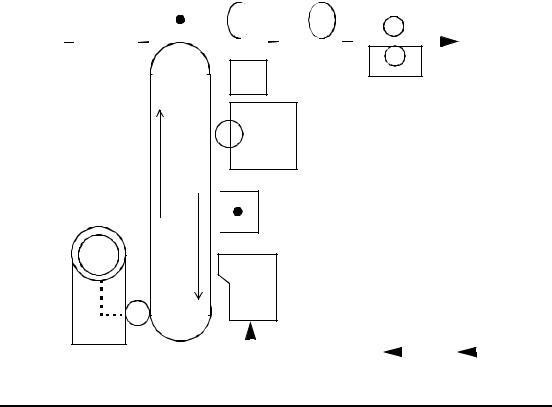
6Activating paper
As the image is being developed, a sheet of paper is transported to the photoconductor belt. The PCL board controls this activity. A series of paper pick-up, feed, and timing rollers guide the paper so the developed image is properly registered with the leading edge of the sheet.
7Transferring the image to the paper
Next, the paper contacts the surface of the photoconductor belt. Above the paper and the belt is the transfer corona, which has a high positive charge, and attracts the developed image from the belt to the surface of the paper. At this point, you can remove the printed image to verify print quality, but the toner is not yet fused.
8Fusing the image to the paper
The vacuum transport unit advances the paper with the developed image to the fuser unit where heat and pressure bond the toner to the paper. The finished print then arrives at the paper output tray.
9Cleaning routine
After a print is made, the photoconductor belt must be cleaned for the next print. The belt first passes the erase lamp where any remaining latent image is erased. The belt continues to the cleaning unit where a charged brush rotates against the surface to remove any residual toner. This toner is recycled to the developer unit for reuse.
|
|
|
|
|
|
Transfer Charger Vacuum Transport |
|
Fuser Unit |
|
||||||||||||||||||||||||||||||
6 |
7 |
|
|
|
|
|
|
|
|
|
|
|
|
|
|
|
|
|
|
|
|
8 |
|
|
|
|
|
|
|
|
|
|
|||||||
|
|
|
|
|
|
|
|
|
|
|
|
|
|
|
|
|
|
|
|
|
|
|
|
|
|
|
|
|
|
||||||||||
|
|
|
|
|
|
|
|
|
|
|
|
|
|
|
|
|
|
|
|
|
|
|
|
|
|
|
|
|
|
|
|
|
|
|
|
|
|
|
|
Paper Input
Toner |
5 |
Developer Unit
Photoconductor |
Paper
Output
Erase Lamp
9 Cleaner
|
3 |
|
Charge Corona |
4 |
LED Printhead |
|
|
|
|
|
|
|
|
|
SI |
|
|
|
|
|
|
|
Bitmap |
|
|
|
|
|
Host |
|||
|
|
|
RAM |
IGS |
|
|
|
1 |
|
|
|
|
|
|
|
2 |
|
|
|
|
|
|
|||
|
|
|
|
|
|
|
|
|
|
|
||
|
|
|
|
|
|
|
|
|
|
|
|
|
|
|
|
|
|
|
|
|
|
|
|
|
|
Figure 1-1. Cycle of Operation
1-4 |
Printer and Troubleshooting Overview |

Paper Path and Cycle Sequence
The IGS board signals the PCL board that a page of data is ready to be printed. When this happens the following sequence takes place.
Simplex Printing
1PCL software downloaded to the PCL board from the disk drive system turns on the main motor.
2The PCL board engages the paper pick clutch which causes the roller to feed a sheet of paper.
3The paper is passed to the feed roller where the PCL board has engaged the feed roller clutch.
4The feed roller passes the paper to the paper timing roller. Prior to reaching the paper timing roller, the paper passes over the paper timing sensor. (If the paper does not energize this sensor in a specified amount of time, an error 020/021 will occur.) The leading edge of the paper is registered against the paper timing roller. The paper timing clutch is engaged and the paper is passed over the photoconductor for transfer. This registers the paper to the printer and the image to the paper. The paper timing sensor signal also alerts the PCL to inform the IGS that it can begin to send the data.
5The PCL board engages the paper timing roller clutch and, at the same time, turns on the transfer charger to provide a high positive voltage. The developed image on the photoconductor comes in contact with the paper and the high positive voltage causes the image to transfer to the paper.
6Because the toner is not yet fixed to the paper, a vacuum transport assembly, gripping the paper from the back side, moves the paper to the fuser unit, where heat and pressure bond the toner to the paper.
7Upon leaving the fuser unit, the paper comes in contact with the paper exit sensor. (If the paper does not energize this sensor in a given amount of time after leaving the paper timing sensor [step 4], an error 022 will occur.)
8The exit roller moves the paper to the exit tray. (If the exit sensor is not cleared in a specified amount of time, an error 023 will occur.)
Duplex Printing
When duplex is selected, the PCL board controls the paper motion with page scheduling assistance from the IGS board. The duplex page router is engaged. When in duplex mode, it is important to note that the printer runs multiple pages through the paper path at the same time to increase speed. (See Figure 1-2, “Paper Path,” on page 1-6 .)
1In a duplex job, the duplex router solenoid behind the fuser is engaged and mechanical fingers route the paper to the duplex area. Also, the “A” roller clutch engages to turn the “A” and “B” rollers (connected via a belt).
Printer and Troubleshooting Overview |
1-5 |
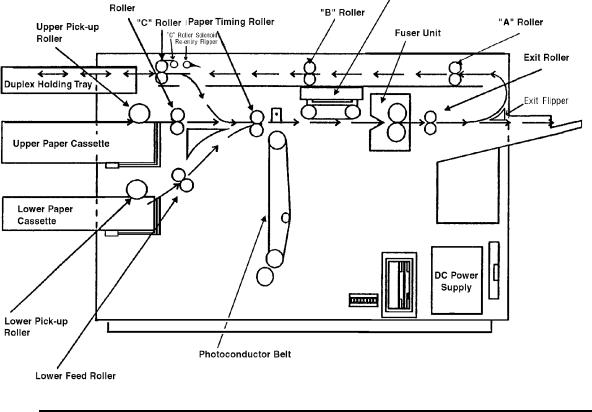
2The paper upon passing through the “B” roller comes in contact with the duplex sensor. (If the paper does not energize this sensor in a given amount of time, an error 060 will occur.)
3The “C” roller bidirectional motor turns on and passes the paper into the turnaround tray. The paper sensor in the turnaround tray is activated and the paper is center registered. (If the paper does not energize this sensor in a given amount of time after leaving the duplex sensor, an error 061 will occur.)
4At this time the solenoid for the router at the turnaround tray engages so the paper can be routed to be printed on the duplex side.
5In a given amount of time after the paper energizes the paper sensor in the turnaround tray, the bi-directional motor reverses and passes the paper to the paper timing roller. (If the paper does not energize the paper timing sensor in a given amount of time after leaving the turnaround sensor, an error 062 will occur.)
6At this point, the same steps happen as during a simplex cycle.
Figure 1-2. Paper Path
1-6 |
Printer and Troubleshooting Overview |
Error Code Technical Definitions
The following table lists the printer error codes and their descriptions.
Table 1-1. Error Code Technical Definitions
Type |
Error |
Description |
|
|
|
|
|
Errors |
010, E10 |
PCL board detected no signal from upper paper cassette empty |
|
|
sensor indicating no paper present |
||
|
|
||
|
|
|
|
Cassette |
011 |
PCL board detected no signal from lower paper cassette empty |
|
013 |
PCL board detected no signal from lower cassette in switch |
||
|
|
sensor indicating no paper present |
|
|
012, E12 |
PCL board detected no signal from upper cassette in switch |
|
|
|
|
|
|
020 |
PCL board detected that the paper being fed from the upper cas- |
|
Path |
|
sette did not reach the timing paper sensor within the allotted time |
|
|
|
||
021 |
PCL board detected that the paper being fed from the lower cas- |
||
Paper |
|
sette did not reach the timing paper sensor within the allotted time |
|
|
|
||
022 |
PCL board detected that the exit paper sensor did not activate or |
||
Primary |
|
the timing sensor did not deactivate within the allotted time |
|
|
|
||
023 |
PCL board detected that either: |
||
|
|||
|
|
1. The exit paper sensor (within the printer) became activated but |
|
the |
|
did not deactivate within the specified time. |
|
|
2. (HCO only). The paper exit sensor (within the HCO) did not |
||
in |
|
become activated or deactivated within the allotted time |
|
|
|
||
Jams |
025 |
PCL board detected that the timing paper sensor was activated |
|
|
|
immediately after one of the covers was closed |
|
|
|
|
|
Paper |
026 |
PCL board detected that either the exit paper sensor (within the |
|
|
printer) or the paper exit sensor (within the HCO) was activated |
||
|
immediately after one of the covers was closed |
||
|
|
|
|
|
027 |
PCL board detected paper in the duplex area after clearing a jam |
|
|
|
|
|
|
030 |
PCL board detected a signal from the high-voltage power supply |
|
|
|
unit indicating an abnormal load on the bias voltage to either the |
|
Errors |
|
developer unit, cleaner unit, or printhead-cleaning bias plates. |
|
|
|
||
031 |
PCL board detected a signal from the toner patch sensor board |
||
Control |
|
indicating that the reference voltage level on the photoconductor |
|
|
indicating that the toner patch on the photoconductor was too light. |
||
|
|
was too low. |
|
|
032 |
PCL board detected a signal from the toner patch sensor board |
|
Toner |
|
|
|
035 |
PCL board detected too many successive signals from the toner |
||
|
|
patch sensor board for a toner feed. |
|
|
|
|
|
|
036 |
PCL board detected no developer unit electrical interlock signal |
|
|
|
from the J25 connector. |
|
|
|
|
Printer and Troubleshooting Overview |
1-7 |
Table 1-1. Error Code Technical Definitions (Continued)
Type |
Error |
Description |
|
|
|
|
040 |
PCL board sensed that the signal from the photoconductor seam |
|
|
sensor either was not of sufficient amplitude or did not show the |
|
|
proper timing. |
|
|
|
|
041 |
PCL board detected an abnormally high amount of current needed |
Errors |
042 |
to drive the photoconductor seam sensor LED (within the photo- |
PCL board detected an open connection to the photoconductor |
||
|
|
conductor unit). |
Rotation |
|
seam sensor LED (within the photoconductor unit). |
|
|
|
044 |
PCL board detected a signal from the high-voltage power supply |
|
|
|
unit indicating that either the main charger or transfer charger cir- |
OPC |
|
cuits have an open connection. |
|
|
|
045 |
PCL board detected a signal from the high-voltage power supply |
|
|
|
unit indicating an abnormally high load on the bias voltage to the |
|
|
main charger. |
|
|
|
|
046 |
PCL board detected a signal from the high-voltage power supply |
|
|
unit indicating an open connection in the main charger circuit (diag- |
|
|
nostic test only). |
|
|
|
|
050 |
PCL board detected a signal from the high-voltage power supply |
Errors |
051 |
unit indicating an abnormally high load on the bias voltage to the |
PCL board detected a signal from the high-voltage power supply |
||
|
|
transfer charger. |
HVPS |
|
unit indicating an open connection in the transfer charger circuit |
|
(diagnostic test only). |
|
|
|
|
|
|
|
|
055 |
PCL board detected that the current needed to drive the erase |
|
|
lamp assembly was either higher or lower than the specified limits. |
|
|
|
|
060 |
PCL board detected that the exit paper sensor did not deactivate |
Jams |
|
or the paper path sensor did not activate within the allotted time. |
|
|
|
061 |
PCL board detected that the duplex paper path sensor did not |
|
Duplex |
|
deactivate, the turnaround tray sensor did not activate in the allot- |
|
ted time, or the duplex paper path sensor activated at POR. |
|
|
|
|
|
|
|
|
062 |
PCL board detected that paper leaving the duplex turnaround tray |
|
|
did not reach the timing sensor within the allotted time or the |
|
|
duplex turnaround sensor was activated at POR. |
|
|
|
Errors |
070 |
PCL board sensed, via the fuser thermistor, that the temperature of |
|
the fuser unit did not change within the allotted time. |
|
|
|
|
|
|
|
|
071 |
PCL board sensed an open connection in the fuser thermistor cir- |
Control |
|
cuit |
|
|
|
072 |
PCL board sensed that the resistance of the fuser thermistor was |
|
|
|
too low indicating that the temperature of the fuser unit was higher |
Fuser |
|
than the specified limit. |
|
|
|
073 |
too high indicating that the temperature of the fuser unit was lower |
|
|
PCL board sensed that the resistance of the fuser thermistor was |
|
|
|
than the specified limit. |
|
|
|
1-8 |
Printer and Troubleshooting Overview |
Table 1-1. Error Code Technical Definitions (Continued)
Type |
Error |
Description |
|
|
|
|
081 |
PCL board activated the jogging motor but did not detect a change |
|
|
in the signal from the front sensor in the job offset assembly (diag- |
|
|
nostic test only). |
|
|
|
|
082 |
PCL board activated the jogging motor but did not detect a change |
|
|
in the signal from the rear sensor in the job offset assembly (diag- |
|
|
nostic test only). |
|
|
|
|
083 |
PCL board activated the jogging motor but did not detect a change |
Errors |
|
in the signal from either the front or rear sensors in the job offset |
|
assembly. |
|
|
|
|
|
|
|
|
084 |
PCL board detected a signal from the duplex control board #2 indi- |
Jogger |
|
cating that the registration side sensor did not activate after com- |
|
mand was sent to the duplex control board #2 to turn on the resist |
|
|
|
motor (diagnostic test only). |
|
|
|
|
085 |
PCL board detected a signal from the duplex control board #2 indi- |
|
|
cating that the registration side sensor did not deactivate after a |
|
|
command was sent to the duplex control board #2 to turn on the |
|
|
resist motor (diagnostic test only). |
|
|
|
|
086 |
PCL board detected a signal from the duplex control board #2 indi- |
|
|
cating that either the registration side sensor was activated and |
|
|
would not deactivate or was deactivated and would not activate |
|
|
after a command was sent to the duplex control board #2 to turn on |
|
|
the resist motor. |
|
|
|
|
090 |
PCL board detected that one of the cover interlocks was not acti- |
Errors |
|
vated (diagnostic test only). |
|
|
|
097 |
PCL board detected a signal from the IGS board indicating the |
|
|
|
absence of +12 Vdc. |
|
|
|
LVPS |
098 |
PCL board detected a signal from the IGS board indicating the |
|
absence of ‚-12 Vdc. |
|
|
|
|
|
|
|
|
099 |
PCL board detected a signal from the IGS board indicating the |
|
|
absence of +24 Vdc. |
|
|
|
|
100, 102 |
IGS board detected a failure of the PCL board status codes. |
|
|
|
|
101 |
PCL board detected that the IGS board was in a halt state (diag- |
|
|
nostic test only). |
|
|
|
|
121-127 |
PCL board detected an error in the communication between the |
|
|
PCL board and the IGS board. |
|
|
|
Errors |
130-134 |
PCL board detected an error during the internal diagnostic testing |
|
of the PCL board. |
|
|
|
|
|
|
|
Controller |
140 |
PCL board detected an error during the internal diagnostic testing |
|
of the PCL board. |
|
|
|
|
|
|
|
|
145 |
PCL board detected an error during the internal diagnostic testing |
|
|
of the PCL board. |
|
|
|
|
160-182 |
PCL board detected an error during the internal diagnostic testing |
|
|
of the PCL board. |
|
|
|
|
199-215 |
PCL board detected an error in the communication between the |
|
|
PCL board and the IGS board. |
|
|
|
|
301-401 |
IGS board detected an error during the internal diagnostic testing |
|
|
of the IGS board. |
|
|
|
Printer and Troubleshooting Overview |
1-9 |
Table 1-1. Error Code Technical Definitions (Continued)
Type |
Error |
Description |
|
|
|
Errors |
405-409 |
IGS board detected an error in the program RAM during the inter- |
450-566 |
IGS board detected an error during the internal diagnostic testing |
|
|
|
nal diagnostic testing of the IGS board. |
DD |
|
of the IGS board and software. |
|
|
|
|
|
|
Controller Errors |
570-586 |
IGS board detected an error when communicating with the floppy |
|
disk drive. |
|
|
|
|
|
|
|
|
600-610 |
IGS board detected an error during the internal diagnostic testing |
|
|
of the IGS board. |
|
|
|
Communication Errors |
701-703 |
IGS board detected an error when communicating with a host |
|
using RS232 communications. |
|
|
|
|
|
|
|
|
770-784 |
IGS board detected an error when communicating with a host |
|
|
using RS422 communications. |
|
|
|
|
888 |
IGS board detected that the PCL board was in a halt or reset state. |
|
|
|
1-10 |
Printer and Troubleshooting Overview |

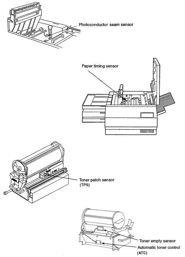
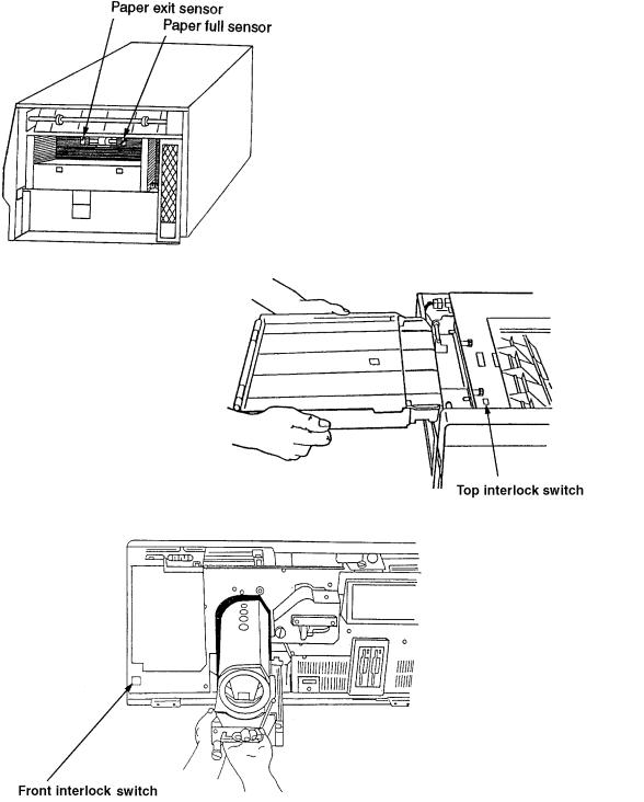
Sensor and Switch Locations
The following pages illustrate the locations of the printer’s sensors and switches. Table 1- 2, “Sensor and Switch List,” on page 1-14 , lists them.
Left end view
Left end view
Front left view
Top view, duplex
Printer and Troubleshooting Overview |
1-11 |
Top view
Front view
Developer right view
Developer left view
1-12 |
Printer and Troubleshooting Overview |
Right side view
Top left, duplex tray view
Front view
Printer and Troubleshooting Overview |
1-13 |
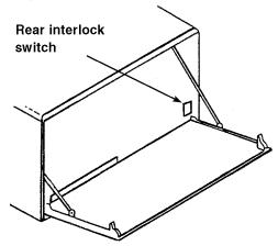
Rear view
Table 1-2. Sensor and Switch List
Sensor/Switch Name |
Page No. |
|
|
Automatic toner control sensor |
1-12 |
|
|
Cassette paper present sensors, upper and lower |
1-11 |
|
|
Cassette present micro switches, upper and lower |
1-11 |
|
|
Duplex registration sensor |
1-11 |
|
|
Duplex paper path sensor |
1-11 |
|
|
Duplex cover interlock switch |
1-11 |
|
|
Interlock switch, top |
1-13 |
|
|
Interlock switch, front |
1-13 |
|
|
Interlock switch, rear |
1-14 |
|
|
Paper exit sensor |
1-13 |
|
|
Paper full sensor |
1-13 |
|
|
Paper size sensors, upper and lower |
1-11 |
|
|
Paper timing sensor |
1-12 |
|
|
Photoconductor seam sensor |
1-12 |
|
|
Toner empty sensor |
1-12 |
|
|
Toner patch sensor |
1-12 |
|
|
1-14 |
Printer and Troubleshooting Overview |

Troubleshooting Overview
Throughout the printer’s life problems occur, such as those indicated when an error code displays on the operator panel, a printer produces poor quality prints, or the printer malfunctions. Use the tools provided in this manual to diagnose and resolve printer problems.
These tools include:
•The Troubleshooting Analysis Guide, which contains troubleshooting procedures called TAGs. TAG 001: Troubleshooting A Printer Problem provides an overview of how to use TAGs.
•Cross reference tables, which link error codes, print quality problems, and mechanical malfunctions to specific TAGs.
•Print quality samples, which you can use to identify a printing problem and its associated TAGs.
•Diagnostics, through which the printer checks itself for a range of problems.
The next several pages review troubleshooting basics and standard procedures followed in every troubleshooting session, including:
•
•
•
•
•
•
•
•
•
•
•
•
•
Identifying whether a problem belongs to the printer or host
Isolating protocol converter problems
Running test prints
Reading the error log
Confirming line power
Using TAGs
Power-On Reset
Installing the interlock by-pass tool
Checking continuity
Producing a developed image
Producing a toner patch
Completing a service call
Clearing the error log
General Troubleshooting Tips
When a printer problem arises, swapping out all printer supplies may temporarily mask the problem. This is an unsatisfactory, short-term, and expensive solution to correcting the problem. Dust and other contamination, rather than printer supplies, are more often the causes of problems. Clean consumable connectors, alignment guides, and areas before changing consumables.
Many failures add excess toner to the printer’s engine. When you are advised to de-tone the printer as part of a problem fix, run at least 200 test prints before evaluating whether the problem has been resolved.
Printer and Troubleshooting Overview |
1-15 |
The Problem: Printer or Host?
The printer is one component in a large host system. Before you start any troubleshooting, make sure that the problem really belongs to the printer rather than to some other component in the host system. Print quality problems and mechanical malfunctions are almost always associated with the printer. However, host interface and software emulation problems can be caused by some other component of the host system even though, at first Z glance, they appear to be printer problems. For instance, text printed in the wrong location on a page, improper page breaks, and missing segments of data strongly indicate a host, not a printer, problem.
The first step in troubleshooting any problem is to isolate the printer from the host system; you can then run test prints. Producing test prints exercises the printer as a stand-alone ones machine, ensuring that the basic printer software and all mechanical functions of the printer are working.
Running Test Prints
To run test prints:
1Disconnect the host interface.
2Run a series of test prints. A directory of the boot device and multiple listings of fonts print, followed by an unformatted and formatted error log. A continuous flow of the test pattern then prints. To run test prints:
•
•
•
For simplex printers, press:
STOP
TEST
For duplex printers, press:
STOP
DUPLEX
TEST
To stop printing the test pattern, press:
STOP
On pressing STOP, the printer will print all test prints stored in the printer’s buffer, then stop.
If the test pattern prints successfully, the problem probably originates with the host system or a protocol converter connected to the host.
1-16 |
Printer and Troubleshooting Overview |
Loading...