


Brocade 16Gb SAN Switch for
nl
HP BladeSystem c-Class
User Guide
HP Part Number: 5697-3043
Published: December 2013
Edition: 2
©Copyright 2013 Hewlett-Packard Development Company, L.P.
©Copyright 2013 Brocade Communications Systems, Incorporated
Warranty
The information contained herein is subject to change without notice. The only warranties for HP products and services are set forth in the express warranty statements accompanying such products and services. Nothing herein should be construed as constituting an additional warranty. HP shall not be liable for technical or editorial errors or omissions contained herein.
Acknowledgements
Microsoft® and Windows® are U.S. registered trademarks of Microsoft Corporation.

Contents |
|
1 Overview.................................................................................................. |
5 |
16Gb SAN Switch features........................................................................................................ |
5 |
Component identification...................................................................................................... |
5 |
Port side of the 16Gb SAN Switch .................................................................................... |
6 |
Internal ports summary......................................................................................................... |
6 |
16Gb SAN Switch redundancy.............................................................................................. |
7 |
16Gb SAN Switch licensing.................................................................................................. |
7 |
ISL trunking groups................................................................................................................... |
7 |
Supported optional software...................................................................................................... |
7 |
Additional software options in HP BladeSystem c-Class Power Pack+ models..................................... |
8 |
Supported SFP transceiver options.............................................................................................. |
8 |
2 Setup...................................................................................................... |
11 |
Kit contents............................................................................................................................ |
11 |
Installation and safety considerations........................................................................................ |
11 |
Installing multiple switches................................................................................................... |
11 |
Electrical considerations...................................................................................................... |
11 |
Environmental considerations .............................................................................................. |
11 |
Installing the 16Gb SAN Switch ............................................................................................... |
12 |
OA power verification........................................................................................................ |
13 |
Verifying the configuration....................................................................................................... |
13 |
Checking LEDs.................................................................................................................. |
14 |
Set the switch Ethernet IP address.............................................................................................. |
14 |
Using EBIPA...................................................................................................................... |
14 |
Using external DHCP ......................................................................................................... |
14 |
Setting the IP address manually............................................................................................ |
14 |
Firmware update.................................................................................................................... |
15 |
Configuring the 16Gb SAN Switch ........................................................................................... |
15 |
Items required for configuration............................................................................................ |
15 |
Connecting to the CLI......................................................................................................... |
15 |
Setting the date and time.................................................................................................... |
16 |
Verifying installed licenses................................................................................................... |
16 |
Modifying the FC domain ID (optional)................................................................................. |
17 |
Disabling and enabling a switch.......................................................................................... |
17 |
Disabling and enabling a port............................................................................................. |
18 |
Using DPOD..................................................................................................................... |
18 |
DPOD commands.............................................................................................................. |
18 |
Backing up the configuration............................................................................................... |
19 |
3 Managing the 16Gb SAN Switch .............................................................. |
20 |
Management features............................................................................................................. |
20 |
Maintaining the 16Gb SAN Switch .......................................................................................... |
20 |
Installing dust covers in empty ports...................................................................................... |
21 |
Replacing an SFP transceiver............................................................................................... |
21 |
Diagnostic tests.................................................................................................................. |
21 |
Powering on and off................................................................................................................ |
22 |
Interpreting LED activity........................................................................................................... |
22 |
LED indicators................................................................................................................... |
22 |
LED patterns........................................................................................................................... |
22 |
Module status LED patterns.................................................................................................. |
22 |
Port link status LED patterns................................................................................................. |
23 |
POST and boot specifications................................................................................................... |
24 |
Contents 3
POST................................................................................................................................ |
24 |
Boot................................................................................................................................. |
24 |
Interpreting POST results..................................................................................................... |
24 |
Firmware update.................................................................................................................... |
25 |
About the reset button............................................................................................................. |
25 |
Rebooting the switch.......................................................................................................... |
25 |
Replacing a faulty 16Gb SAN Switch........................................................................................ |
25 |
4 Support and other resources...................................................................... |
27 |
Intended audience.................................................................................................................. |
27 |
SAN Switch related documentation........................................................................................... |
27 |
HP BladeSystem c-Class related documentation........................................................................... |
27 |
Before you contact HP Technical Support................................................................................... |
27 |
HP contact information............................................................................................................ |
27 |
Document conventions and symbols.......................................................................................... |
28 |
Subscription service................................................................................................................ |
28 |
Other HP websites.................................................................................................................. |
29 |
Documentation feedback......................................................................................................... |
29 |
A Regulatory information.............................................................................. |
30 |
Turkey RoHS material content declaration................................................................................... |
30 |
Ukraine RoHS material content declaration................................................................................ |
30 |
Warranty information.............................................................................................................. |
30 |
B Electrostatic discharge and grounding recommendations............................... |
31 |
Electrostatic discharge recommendations................................................................................... |
31 |
Grounding methods................................................................................................................ |
31 |
C SAN Switch technical specifications............................................................ |
32 |
General specifications............................................................................................................. |
32 |
Weight and physical dimensions.............................................................................................. |
33 |
Environmental requirements...................................................................................................... |
33 |
Supported SFPs...................................................................................................................... |
33 |
Supported HBAs..................................................................................................................... |
33 |
Glossary.................................................................................................... |
34 |
Index......................................................................................................... |
40 |
4Contents

1 Overview
The Brocade 16Gb SAN Switch is an FC switch that supports link speeds of up to 16 Gbps. The 16Gb SAN Switch can operate in a fabric containing multiple switches or it can operate as the only switch in a fabric.
NOTE: In this document, the Brocade 16Gb SAN Switch refers to those Brocade FC switch modules compatible with the HP BladeSystem c-Class enclosure only.
16Gb SAN Switch features
The 16Gb SAN Switch provides the following features:
•Fully integrated, embedded FC SAN design that connects directly to the HP BladeSystem c-Class enclosure midplane
•DPOD, which automatically detects port connections, assigns port licenses, and enables ports
•Easy-to-manage HP Systems Insight Manager support
•Full compatibility with HP B-series switches and Brocade fabrics
•Sixteen internal 8/16 Gbps auto-sensing ports with the following characteristics:
◦Independent automatic negotiation to the highest common speed for each server FC port connected to the switch
◦Universal self-configuring ports, which are capable of becoming F_Ports (fabric enabled)
•Twelve external 4/8/16 Gbps FC SFP ports, with the following characteristics:
◦Automatic negotiation to the highest common speed of all devices connected to the port
◦Port-interface-compatible SFP transceivers, both SWL and LWL
◦Universal self-configuring ports, which are capable of becoming F_Ports, FL_Ports (fabric loop enabled), or E_Ports (expansion ports)
•Heterogeneous support for mixed storage fabrics
•Power supplies controlled by the BladeSystem enclosure
•Identification to HP chassis management with HP specified SEEPROMs
•Hot-swap capability
•Compatibility with redundant and dual redundant switch configurations in c-Class BladeSystem
•Hot code activation
•Real-time clock
•SFP port monitoring
Component identification
Figure 1 (page 6) identifies the physical components of the 16Gb SAN Switch.
16Gb SAN Switch features 5
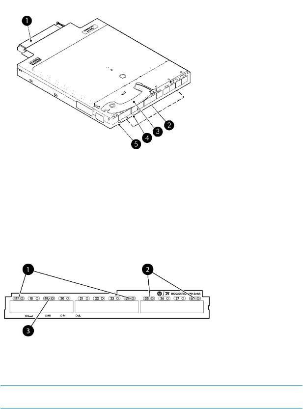
Figure 1 Brocade 16Gb SAN Switch components
1. Midplane connector |
2. External FC ports |
|
3. |
Installation handle |
4. Unit ID (UID), Health LED, and Status LEDs |
5. |
Reset button |
|
Port side of the 16Gb SAN Switch
Figure 2 (page 6) identifies the 16Gb SAN Switch external ports (ports 17 through 20, and ports 21 through 0).
Figure 2 External ports
1. Trunk Group A (ports 17 through 24)
3. User port number
2. Trunk Group B (ports 25 through 0)
NOTE: See Interpreting LED activity (page 22) for complete information on 16Gb SAN Switch LEDs.
Internal ports summary
Sixteen logical internal ports (numbered 1 through 16) connect sequentially to server bays 1 through 16 with the enclosure midplane. Server bay 1 is connected to Switch Port 1, Server bay 2 is connected to Switch port 2, and so forth.
6Overview

16Gb SAN Switch redundancy
The HP BladeSystem c-Class was engineered as a no-single-point-of-failure bladed solution. Attributes that contribute to switch redundancy include:
•Redundant power and cooling
•Redundant HP OA sure management access to the switch
NOTE: The HP OA is the enclosure management module that supports and manages the HP BladeSystem c-Class and all managed devices used in the enclosure.
16Gb SAN Switch licensing
The 16Gb SAN Switch integrates one of three license options that complement existing HP product lines. Models and their specific licenses are as follows:
•Brocade 16Gb/16 SAN Switch for HP BladeSystem c-Class, base, integrating 16 active ports (in any combination of internal and external ports). Software components include a Full Fabric license, the Advanced Web Tools GUI, and Zoning software
•Brocade 16Gb/28 SAN Switch for HP BladeSystem c-Class, base, integrating 28 active ports (16 internal and 12 external). Software components include a Full Fabric license, Advanced Web Tools GUI, and Zoning software
•Brocade 16Gb/28 SAN Switch Pwr Pk+ for HP BladeSystem c-Class, integrating 28 active ports (16 internal and 12 external). Software components include a Full Fabric license, Advanced Web Tools GUI, and zoning software, plus these additional software options:
◦Fabric Watch
◦ISL Trunking
◦Advanced Performance Monitoring
◦Extended Fabrics
NOTE: Adaptive Networking and Server Application Optimization features are included by default in all Fabric OS releases for this switch and do not require a separate license.
IMPORTANT: Upgrade the 16Gb SAN Switch by purchasing optional licenses; see the latest version of the HP Fabric OS Administrator Guide to learn how to add a license.
ISL trunking groups
If your 16Gb SAN Switch is licensed for ISL trunking, use the trunking groups available on the switch.
The FC ports are numbered from left to right, and are part of the same ISL trunking group. The trunking group consists of the ports shown in Figure 2 (page 6).
NOTE: ISL Trunking is optional software that allows you to create trunking groups of ISLs between adjacent switches. ISL trunking is available on the Brocade 16Gb SAN Switch Power Pack+ model, or by purchasing the optional license described in “16Gb SAN Switch licensing” (page 7). For more information about trunking, see the latest version of the HP Fabric OS Administrator Guide.
Supported optional software
Table 1 (page 8) lists the optional software kits and licenses, which can be activated by purchasing a license key.
NOTE: Availability of optional components may change.
ISL trunking groups |
7 |

Table 1 Optional software
 Option
Brocade 16Gb SAN Switch for HP BladeSystem c-Class Power Pack+ Upgrade LTU
 HP StoreFabric B-series 8Gb and 16Gb SAN Director Switch Fabric Vision LTU 1
Brocade 8 and 16 Gb SAN Switch for HP BladeSystem c-Class 12-port Upgrade LTU
 Fabric Watch2
ISL Trunking
 Advanced Performance Monitoring2
Extended Fabrics2
 HP B-series SAN Network Advisor Enterprise Software
HP B-series SAN Network Advisor Professional Plus Software
 HP B-series SAN Network Advisor Professional Plus Upgrade Software
1 Fabric OS 7.2.0a or later
2To obtain Fabric Watch, Advanced Performance Monitoring, or Extended Fabrics Software, a purchase of the TC464A Power Pack+ Software Bundle is required.
NOTE: For the latest information on supported software components, see the Product QuickSpecs available from the HP website: http://h18004.www1.hp.com/products/quickspecs/14647_na/ 14647_na.pdf.
Additional software options in HP BladeSystem c-Class Power Pack+ models
The 16Gb SAN Switch Power Pack+ includes the following optional software:
•ISL Trunking
•Fabric Watch
•Advanced Performance Monitoring
•Extended Fabrics
For information on any of these options, see the latest version of the HP Fabric OS Administrator Guide.
NOTE: Adaptive Networking and Server Application Optimization options are included by default in all Fabric OS releases for this switch and do not require a separate license.
Supported SFP transceiver options
Table 2 (page 8) lists the only supported SFPs, Table 3 (page 9) lists the supported optical cables, and Table 4 (page 9) lists the supported Fibre Channel cables.
Table 2 Supported SFPs
Option |
Part number |
16 Gb Optical Transceivers (SFP+) |
|
HP B-series 16Gb SFP+ Short Wave Transceiver |
QK724A |
HP B-series 16Gb SFP+ Long Wave 10 Km Transceiver |
QK725A |
8 Gb Optical Transceivers (SFP+) |
|
Short Wave: HP 8Gb Short Wave B-series FC SFP+ 1 Pack |
AJ716B |
8Overview

 Table 2 Supported SFPs (continued)
Option |
Part number |
Long Wave: HP 8Gb Long Wave B-series 10 km FC SFP+ |
AJ717A |
1 Pack |
|
Extended Long Wave: HP 8Gb Long Wave B-series 25 km |
AW538A |
FC SFP+ 1Pack |
|
Table 3 Optical cables
Option |
Part number |
1m HP PremierFlex OM4 LC/LC Multi-mode |
QK732A |
2m HP PremierFlex OM4 LC/LC Multi-mode |
QK733A |
5m HP PremierFlex OM4 LC/LC Multi-mode |
QK734A |
15m HP PremierFlex OM4 LC/LC Multi-mode |
QK735A |
30m HP PremierFlex OM4 LC/LC Multi-mode |
QK736A |
50m HP PremierFlex OM4 LC/LC Multi-mode |
QK737A |
Table 4 LC-LC FC cables for use between 4/8 Gb and 4/8 Gb FC devices
Option |
Part number |
0.5 m LC-LC Multi-Mode OM3 |
AJ833A |
1 m LC-LC Multi-Mode OM3 |
AJ834A |
2 m LC-LC Multi-Mode OM3 |
AJ835A |
5 m LC-LC Multi-Mode OM3 |
AJ836A |
15 m LC-LC Multi-Mode OM3 |
AJ837A |
30 m LC-LC Multi-Mode OM3 |
AJ838A |
50 m LC-LC Multi-Mode OM3 |
AJ839A |
Table 5 (page 10) provides transceiver, port speed, and cable data transmission ranges.
Supported SFP transceiver options |
9 |

Table 5 Optic, speed, cable, and distance data transmission ranges
|
|
|
|
|
|
Multimode media |
|
|
|
Transceiver |
Form |
|
|
62.5 µm |
50 µm (OM2) |
50 µm |
50 µm (OM4) |
Single mode |
|
type |
factor |
Speed |
(OM1) |
|
(OM3) |
|
media 9 µm |
||
SWL |
SFP+ |
2 |
Gbps1 |
150 m (492 |
300 m (984 |
500 m |
N/A |
N/A |
|
|
|
|
|
|
ft) |
ft) |
(1,640 ft) |
|
|
|
|
SFP+ |
4 |
Gbps2 |
70 m (229 ft) |
150 m (492 |
380 m |
400 m |
N/A |
|
|
|
|
|
|
ft) |
(1,48 ft) |
(1,312 ft) |
|
|
|
SFP+ |
8 |
Gbps |
21 m (68 ft) |
50 m (164 ft) |
150 m (492 |
190 m (623 |
N/A |
|
|
|
|
|
|
|
ft) |
ft) |
|
|
|
SFP+ |
16 Gbps |
15m (49 ft) |
35 m (115 ft) |
100 m (328 |
125 m (410 |
N/A |
|
|
|
|
|
|
|
|
ft) |
ft) |
|
LWL |
SFP+ |
2, 4, 8, 16 |
N/A |
N/A |
N/A |
N/A |
10 km (6.2 |
||
|
|
|
Gbps1, 2 |
|
|
|
|
mi) |
|
ELWL |
SFP+ |
2, 4 Gbps1, 2 |
N/A |
N/A |
N/A |
N/A |
30 km (18.6 |
||
|
|
|
|
|
|
|
|
|
mi) |
|
|
SFP+ |
8 |
Gbps |
N/A |
N/A |
N/A |
N/A |
25 km (15.5 |
|
|
|
|
|
|
|
|
|
mi) |
1 |
2 Gbps SFPs are not supported on this switch. |
|
|
|
|
||||
2 |
4 Gbps SFPs are not supported on this switch |
|
|
|
|
||||
10 Overview
2 Setup
Kit contents
The Brocade 16Gb SAN Switch kit contains:
•Brocade 16 Gb SAN Switch for HP BladeSystem c-Class Quick Start Instructions
•One of the following switch models:
◦Brocade 16Gb/16-ports enabled SAN Switch for HP BladeSystem c-Class
◦Brocade 16Gb/28-ports enabled SAN Switch HP BladeSystem c-Class
◦Brocade 16Gb/28-ports enabled SAN Switch Pwr Pk+ HP BladeSystem c-Class
•HP Read Me First document
•HP End User License Agreement letter
Installation and safety considerations
The 16Gb SAN Switch installs in the I/O bays in the rear of the HP BladeSystem c-Class enclosure. See the appropriate BladeSystem Enclosure Setup and Installation Guide for specific enclosure requirements.
Installing multiple switches
If you do not have a DHCP server connected to the OA, install and configure one 16Gb SAN Switch at a time. This is required so that Ethernet IP address conflicts do not occur with duplicate default Ethernet IP addresses.
IMPORTANT: DHCP is enabled by default on this switch. In cases where DHCP is available, IP address conflicts do not occur, simplifying multiple switch installations. See “Using external DHCP ” (page 14). See also the most current documentation for interconnects and other HP BladeSystem c-Class components at the HP website: http://www.hp.com/go/bladesystem/interconnects.
Each switch must be assigned a unique Ethernet IP address during configuration. Once the default Ethernet IP address on the 16Gb SAN Switch has been changed, you may install additional 16Gb SAN Switches in the enclosure.
See the appropriate HP BladeSystem Enclosure Setup and Installation Guide for help identifying your specific enclosure setup, available connections, and power requirements.
Electrical considerations
The 16Gb SAN Switch requires 35 watts, provided by the enclosure. No other power requirement or provision exists.
Environmental considerations
Ensure proper cooling and ventilation by verifying the following:
•The air vents on the enclosure are not blocked or restricted.
•The ambient air temperature at the front of the enclosure does not exceed 35°C (95°F) while the switch is operating.
IMPORTANT: The dust covers that ship with your 16Gb SAN Switch must be inserted into any ports where SFPs are not installed, to help contain air flow in the BladeSystem chassis.
Kit contents |
11 |
Installing the 16Gb SAN Switch
For help identifying your specific enclosure setup and available connections, see the HP BladeSystem c-Class Enclosure Setup and Installation Guide, provided with your enclosure, or the HP website http://www.hp.com/go/bladesystem/documentation.
Install the Brocade 16Gb SAN Switch into the enclosure:
1.Locate the appropriate interconnect bay in the rear of the enclosure.
CAUTION: Properly ground yourself before handling the switch.
NOTE: Populate all enclosure interconnect bays with an interconnect module or one of the blank panels provided.
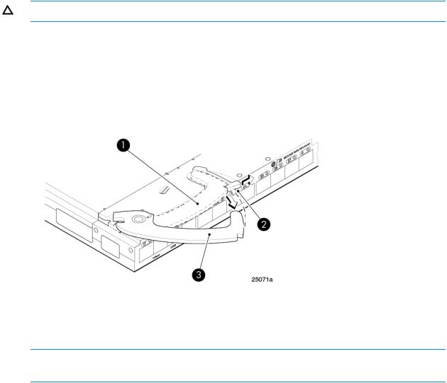
2.Press the handle latch to release the installation handle.
Figure 3 Releasing the installation handle
1. Installation handle latched position |
2. Handle latch |
3. Installation handle released
NOTE: The Brocade 16Gb SAN Switch for HP BladeSystem c-Class is a hot-pluggable device. The enclosure power may be on or off during installation.
3.Align the Brocade 16Gb SAN Switch for HP BladeSystem c-Class with the appropriate interconnect bay according to your enclosure’s specific configuration. Push the switch firmly into the interconnect bay.
12 Setup
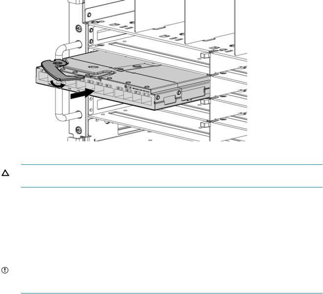
Figure 4 Installing the Brocade 16Gb SAN Switch for HP BladeSystem c-Class into an interconnect bay
4.Press the installation handle into the latch to lock the Switch in place.
CAUTION: For proper cooling and EMI emissions control, all panels and doors should be in place and securely fastened while the switch is in operation.
NOTE: The HP BladeSystem c7000 Platinum Enclosure is required to permit 16 Gbps speed. Other HP BladeSystem c7000 Enclosures have a maximum speed of 8 Gbps.
OA power verification
The OA is the enclosure management processor that manages the devices contained within the enclosure. The OA provides a single point from which to perform basic management tasks on switches or server blades installed in the enclosure.
IMPORTANT: HP recommends reading the appropriate HP BladeSystem Enclosure User Guide and the HP BladeSystem Onboard Administrator User Guide. Reading these guides in sequence will promote an overall understanding of your specific enclosure model.
Once the switch is installed in the interconnect bay, the OA verifies that the switch type matches the mezzanine cards present on the servers. If there is no mismatch, the OA powers up the switch.
If the switch does not power up, check the enclosure and switch status with the OA web interface. See the HP BladeSystem Onboard Administrator User Guide for more information.
Verifying the configuration
The OA is the enclosure management module that supports and manages the HP BladeSystem c-Class enclosure and all the devices used in the enclosure.
Once the switch is installed in the interconnect bay, the OA verifies that the switch type matches the mezzanine cards present on the server blades. If there is no mismatch, the OA powers up the switch.
If the switch does not power up, check the enclosure and switch status using the OA web interface. See the HP BladeSystem Onboard Administrator User Guide for more information and troubleshooting tips.
Verifying the configuration |
13 |
 Loading...