


BLADESYSTEM C3000
Table of contents
 Loading...
HP BladeSystem c3000 Tower Enclosure Setup and Installation Guide
Part Number 457022-002
August 2008 (Second Edition)

© Copyright 2007, 2008 Hewlett-Packard Development Company, L.P.
The information contained herein is subject to change without notice. The only warranties for HP products and services are set forth in the express
warranty statements accompanying such products and services. Nothing herein should be construed as constituting an additional warranty. HP
shall not be liable for technical or editorial errors or omissions contained herein.
Microsoft, Windows, and Windows Server are U.S. registered trademarks of Microsoft Corporation.
Intended audience
This document is for the person who installs, administers, and troubleshoots servers and storage systems. HP assumes you are qualified in the
servicing of computer equipment and trained in recognizing hazards in products with hazardous energy levels.

Contents
Planning the installation................................................................................................................. 5
Pallet contents........................................................................................................................................... 5
Installation environment requirements........................................................................................................... 6
Warning, caution, and important messages.................................................................................................. 7
Space and airflow requirements.................................................................................................................. 8
Temperature requirements .......................................................................................................................... 9
Power requirements ................................................................................................................................... 9
Grounding requirements............................................................................................................................. 9
Identifying components and LEDs.................................................................................................. 11
Enclosure front components ...................................................................................................................... 11
Device bay numbering ................................................................................................................... 11
HP BladeSystem Insight Display components ..................................................................................... 13
HP BladeSystem Onboard Administrator components.........................................................................13
Enclosure rear components ....................................................................................................................... 14
Fan bay numbering ....................................................................................................................... 15
Fan LEDs ...................................................................................................................................... 15
Power supply bay numbering.......................................................................................................... 16
Power supply LED.......................................................................................................................... 16
Interconnect bay numbering............................................................................................................ 17
Installing components .................................................................................................................. 18
Setting up the enclosure ...........................................................................................................................18
Component installation ............................................................................................................................ 18
Installing a power supply................................................................................................................ 19
Installing a full-height blade ............................................................................................................ 20
Installing a half-height blade ........................................................................................................... 26
Installing fans................................................................................................................................ 29
Installing an HP BladeSystem c3000 KVM module............................................................................ 30
Installing interconnect modules ........................................................................................................ 33
Cabling and powering up the enclosure........................................................................................ 44
Cabling the enclosure .............................................................................................................................. 44
HP BladeSystem Onboard Administrator cabling ............................................................................... 44
Cabling a PC to the enclosure service port........................................................................................ 45
Cabling the network to the enclosure ............................................................................................... 45
Installing a PDU ......................................................................................................................................45
Powering up the enclosure........................................................................................................................ 46
Using the HP BladeSystem Insight Display...................................................................................... 47
Insight Display overview........................................................................................................................... 47
Running the Insight Display installation steps............................................................................................... 47
Accessing the HP BladeSystem Insight Display............................................................................................. 52
Navigating the Insight Display .................................................................................................................. 53
Health Summary screen.................................................................................................................. 54
Enclosure Settings screen................................................................................................................ 55
Enclosure Info screen ..................................................................................................................... 55
Contents 3

Blade or Port Info screen ................................................................................................................ 56
Turn Enclosure UID On/Off screen................................................................................................... 57
View User Note screen................................................................................................................... 59
Chat Mode screen......................................................................................................................... 59
Troubleshooting.......................................................................................................................... 60
Troubleshooting resources ........................................................................................................................60
Important safety information...................................................................................................................... 60
Symbols on equipment ................................................................................................................... 60
Warnings and cautions.................................................................................................................. 61
Insight Display errors ............................................................................................................................... 62
Power errors ................................................................................................................................. 62
Cooling errors............................................................................................................................... 63
Location errors .............................................................................................................................. 63
Configuration errors....................................................................................................................... 63
Device failure errors....................................................................................................................... 63
Technical support........................................................................................................................ 65
Before you contact HP.............................................................................................................................. 65
HP contact information............................................................................................................................. 65
Customer Self Repair ...............................................................................................................................65
Regulatory compliance notices ..................................................................................................... 73
Regulatory compliance identification numbers............................................................................................. 73
Federal Communications Commission notice............................................................................................... 73
FCC rating label............................................................................................................................ 73
Class A equipment......................................................................................................................... 73
Class B equipment......................................................................................................................... 73
Declaration of conformity for products marked with the FCC logo, United States only....................................... 74
Modifications.......................................................................................................................................... 74
Cables................................................................................................................................................... 74
Canadian notice (Avis Canadien).............................................................................................................. 75
European Union regulatory notice .............................................................................................................75
Disposal of waste equipment by users in private households in the European Union......................................... 75
Japanese notice ...................................................................................................................................... 76
BSMI notice............................................................................................................................................ 76
Korean notice ......................................................................................................................................... 76
Chinese notice ........................................................................................................................................ 77
Laser compliance .................................................................................................................................... 77
Battery replacement notice........................................................................................................................ 77
Taiwan battery recycling notice................................................................................................................. 78
Power cord statement for Japan................................................................................................................. 78
Electrostatic discharge................................................................................................................. 79
Preventing electrostatic discharge..............................................................................................................79
Grounding methods to prevent electrostatic discharge.................................................................................. 79
Acronyms and abbreviations........................................................................................................ 80
Index......................................................................................................................................... 82
Contents 4
Planning the installation
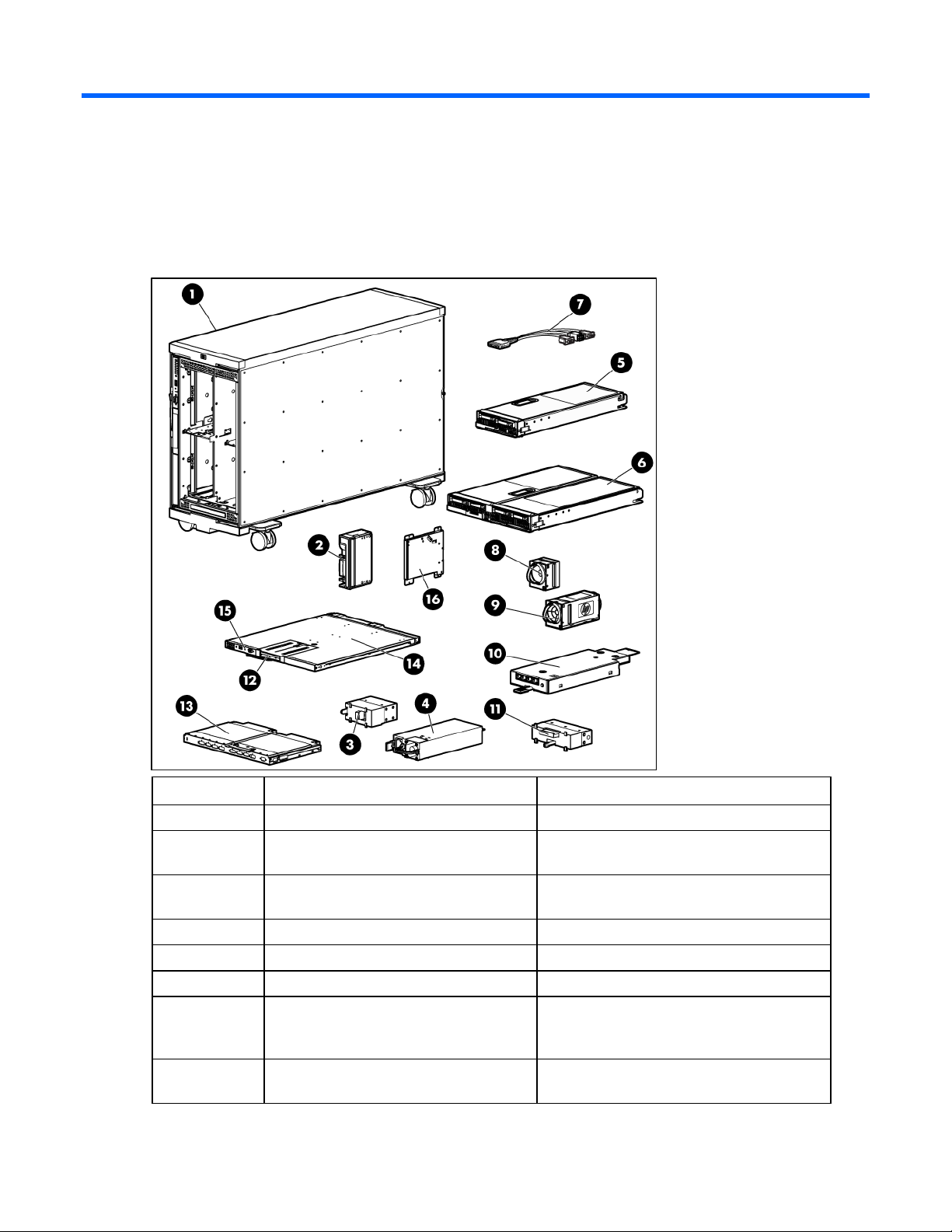
Pallet contents
Item Name Description
1 HP BladeSystem c3000 Tower Enclosure The HP BladeSystem tower enclosure
2 Device bay blank A mandatory insert installed in any unused
device bay
3 Power supply blank A mandatory insert installed in any unused
power supply bay
4 Power supply (quantity as ordered) The power supply for the enclosure
5 Half-height device (quantity as ordered) A half-height server or storage blade
6 Full-height device (quantity as ordered) A full-height server or storage blade
7 HP c-Class Blade SUV cable (local I/O
cable)
8 Fan blank A mandatory insert installed in any unused fan
A cable with serial, USB, and video
connectors that attaches to the I/O connector
on the front of a blade
bay
Planning the installation 5

Item Name Description
9 HP Active Cool fan (quantity as ordered) A fan used to cool the components installed in
the enclosure
10 Enclosure/Onboard Administrator link
module
11 Module blank A mandatory cover installed in the reserved
12 HP BladeSystem Insight Display A display that provides information about the
13 Interconnect module (quantity and type as
ordered)
14 Onboard Administrator tray A removable tray that houses the Onboard
15 Onboard Administrator module The module used to manage the components
16 DVD drive An optional DVD drive for the enclosure
17* Onboard Administrator blank A mandatory cover installed in any unused
18* Interconnect blank A mandatory insert installed in any unused
19* Documentation CD A CD containing detailed documentation
20* SmartStart CD A CD containing SmartStart software that
21* Printed installation instructions The printed installation instructions for blades,
22* Installation checklist A checklist that guides you through installation
* Not shown
The module used to provide enclosure-link
connectivity and Onboard
Administrator/iLO/interconnect management
access
module bay
health and operation of the enclosure
Any of several components, such as pass-
throughs or switches that enable
communication between the blade and the
enclosure
Administrator module and Insight Display
installed in the enclosure. The module is built
into the Onboard Administrator tray for a
single Onboard Administrator.
Onboard Administrator bay
interconnect bay
about using the enclosure
optimizes single-server setup
options, and interconnects
of the enclosure and its components
Installation environment requirements
The HP BladeSystem c3000 Tower Enclosure (referred to as the enclosure) is designed to be used in a
rack-free environment. The following conditions must be met when performing a rack-free installation:
• A fully populated enclosure can weigh up to 153.7 kg (338.9 lb). The object supporting the
enclosure must be able to withstand this weight.
• The enclosure should be supported by a sturdy, flat surface.
Planning the installation 6
WARNING: To reduce the risk of personal injury or damage to the equipment in a rack-free
environment:
• Never stack an enclosure on top of another enclosure.
• Never place equipment on top of an enclosure.
• Never place an enclosure on a surface that cannot support up to 153.7 kg (338.9 lb).
Warning, caution, and important messages
WARNING: To reduce the risk of personal injury or damage to equipment, heed all warnings
and cautions throughout the installation instructions.
WARNING: The enclosure is very heavy. To reduce the risk of personal injury or damage to
the equipment, observe local occupational health and safety requirements and guidelines for
manual material handling.
WARNING: To reduce the risk of personal injury or damage to the equipment, you must
adequately support enclosures during installation and removal.
These symbols, on power supplies or systems, indicate that the equipment is supplied
by multiple sources of power.
WARNING: To reduce the risk of injury from electric shock, remove all power cords
to completely disconnect power from the system.
• Each enclosure has two or more power supply cords. A single rack or cabinet
may contain more than one enclosure. Power may be supplied in a redundant
fashion. Removing any single source of power does not necessarily remove power
from any portion of the system. When performing any service other than hot-plug
module replacement, you must completely disconnect all power to that portion of
the system.
• When performing service procedures on enclosures, shut off the circuit breakers to
both A and B AC power feeds and then disconnect all power cords from the
WARNING: To reduce the risk of personal injury from hot surfaces, allow the drives and the
outlets before servicing.
internal system components to cool before touching them.
WARNING: To reduce the risk of electric shock or damage to the equipment, enter enclosures
or perform service on system components only as instructed in the user documentation.
Planning the installation 7

WARNING: A risk of electric shock from high leakage current exists. Before connecting the AC
supply to the power enclosures, be sure that the electrical outlets are properly grounded
(earthed).
The area where the enclosure is installed should be designated as a restricted access area,
and the enclosure is intended to be used with a dedicated uninterruptible power supply (UPS)
that uses an industrial style wall plug to insure a reliable protective earth ground connection.
Each power supply in the enclosure can also be plugged directly into a low-line wall outlet. Be
sure there is enough total amperage available in the wall outlets of your facility to handle all
power supplies installed in the enclosure. To determine the total amperage draw of your HP
BladeSystem c3000 Tower Enclosure configuration, see the HP power calculator
(http://www.hp.com/go/bladesystem/powercalculator
).
Only trained service personnel must perform installation and maintenance.
CAUTION: Always be sure that equipment is properly grounded and that you follow proper
grounding procedures before beginning any installation procedure. Improper grounding can
result in ESD damage to electronic components. For more information, refer to, "Electrostatic
discharge (on page 79)."
CAUTION: When performing non-hot-plug operations, you must power down the server blade
and/or the system. Use caution when performing other operations, such as hot-plug
installations or troubleshooting.
CAUTION: Protect the equipment from AC power fluctuations and temporary interruptions with
a regulating facility UPS device. This device protects the hardware from damage caused by
power surges and voltage spikes and keeps the system in operation during a power failure.
IMPORTANT: Data on the dimensions and weights of HP BladeSystem c-Class components can
be found in the HP BladeSystem c-Class Maintenance and Service Guide. The same data can
be determined by using the online HP BladeSystem c-Class Sizing Utility.
Space and airflow requirements
To enable servicing and ensure adequate airflow, observe the following spatial requirements when
deciding where to install the HP BladeSystem c3000 Tower Enclosure:
• Leave a minimum clearance of 63.5 cm (25 in) in front of the enclosure.
• Leave a minimum clearance of 76.2 cm (30 in) in back of the enclosure.
• Leave a minimum clearance of 121.9 cm (48 in) from the back of the enclosure to the rear of
another enclosure, rack, or row of racks.
HP BladeSystem servers draw cool air in through the front and expel warm air through the rear of the
enclosure. Therefore, the front of the enclosure must be adequately ventilated to enable ambient room air
to enter the enclosure, and the rear of the enclosure must be adequately ventilated to enable the warm air
to escape from the enclosure.
IMPORTANT: Do not block the ventilation openings.
Planning the installation 8

If the enclosure is not completely filled with components, the remaining gaps between the components can
cause changes in the airflow, which can adversely affect cooling within the enclosure. Fill these gaps with
blanks.
CAUTION: Always use blanks to fill empty spaces in enclosures. This arrangement ensures
proper airflow. Using an enclosure without the proper blanks results in improper cooling that
can lead to thermal damage.
Temperature requirements
To ensure continued safe and reliable equipment operation, install or position the enclosure in a wellventilated, climate-controlled environment.
The operating temperature inside the enclosure is higher than the room temperature and is dependent on
the configuration of equipment in the enclosure. Check the TMRA for each piece of equipment before
installation.
CAUTION: To reduce the risk of damage to the equipment when installing third-party options:
• Do not permit optional equipment to impede airflow around the enclosure or to increase the
internal enclosure temperature beyond the maximum allowable limits.
• Do not exceed the TMRA of the manufacturer.
Power requirements
Installation of this equipment must comply with local and regional electrical regulations governing the
installation of IT equipment by licensed electricians. This equipment is designed to operate in installations
covered by NFPA 70, 1999 Edition (National Electric Code) and NFPA-75, 1992 (code for Protection of
Electronic Computer/Data Processing Equipment). For electrical power ratings on options, refer to the
product rating label or the user documentation supplied with that option.
WARNING: To reduce the risk of personal injury, fire, or damage to the equipment, do not
overload the AC supply branch circuit that provides power to the enclosure. Consult the
electrical authority having jurisdiction over wiring and installation requirements of your facility.
CAUTION: Protect the enclosure from power fluctuations and temporary interruptions with a
regulating UPS. This device protects the hardware from damage caused by power surges and
voltage spikes and keeps the enclosure in operation during a power failure.
Grounding requirements
This equipment must be grounded properly for proper operation and safety. In the United States, you must
install the equipment in accordance with NFPA 70, 1999 Edition (National Electric Code), Article 250,
as well as any local and regional building codes.
In Canada, you must install the equipment in accordance with Canadian Standards Association, CSA
C22.1, Canadian Electrical Code.
In all other countries, you must install the equipment in accordance with any regional or national electrical
wiring codes, such as the International Electrotechnical Commission (IEC) Code 364, parts 1 through 7.
Planning the installation 9

Furthermore, you must be sure that all power distribution devices used in the installation, such as branch
wiring and receptacles, are listed or certified grounding-type devices.
Because of the high ground-leakage currents associated with this equipment, HP recommends the use of a
PDU that is either permanently wired to the building’s branch circuit or includes a nondetachable cord
that is wired to an industrial-style plug. NEMA locking-style plugs or those complying with IEC 60309 are
considered suitable for this purpose. Using common power outlet strips to supply power to this equipment
is not recommended.
Planning the installation 10
Identifying components and LEDs
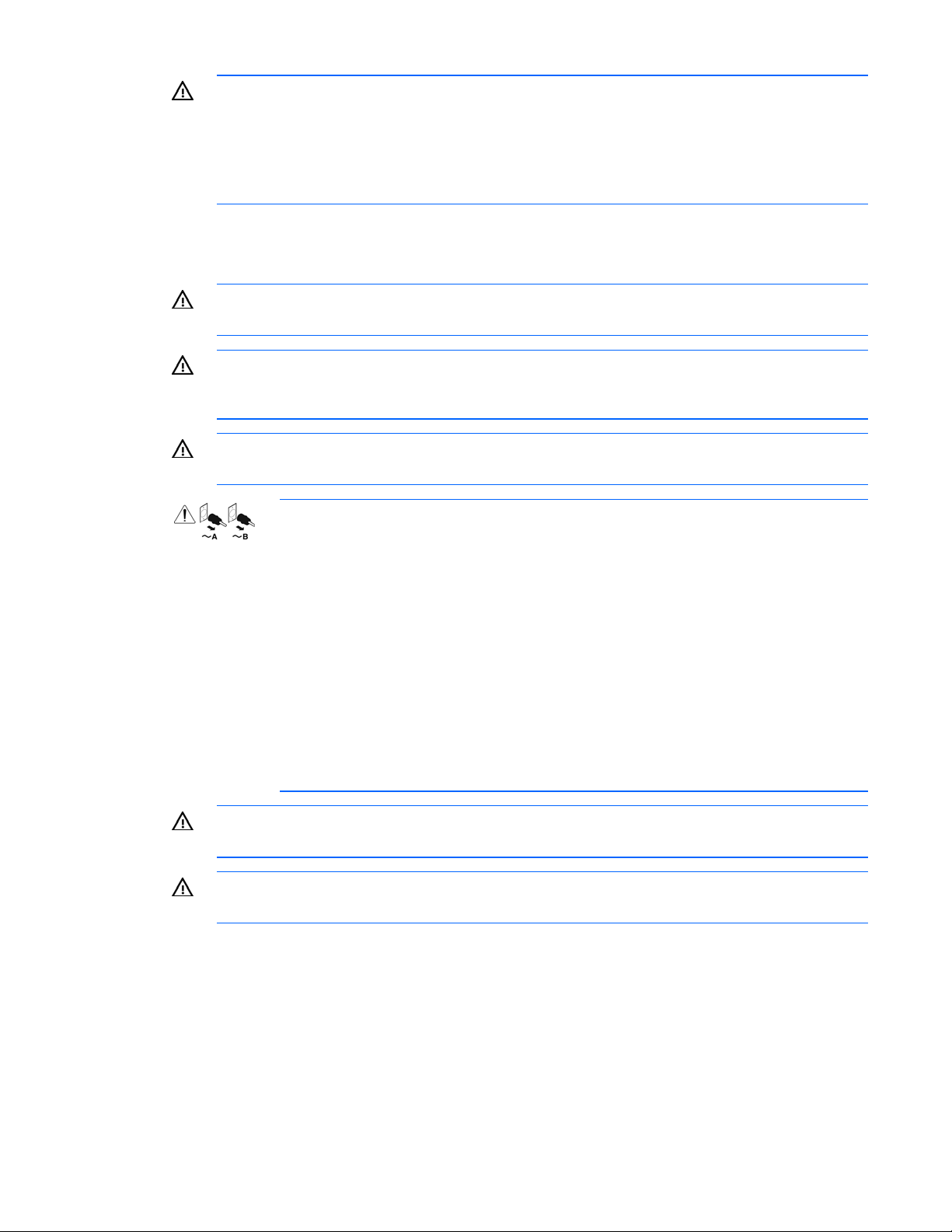
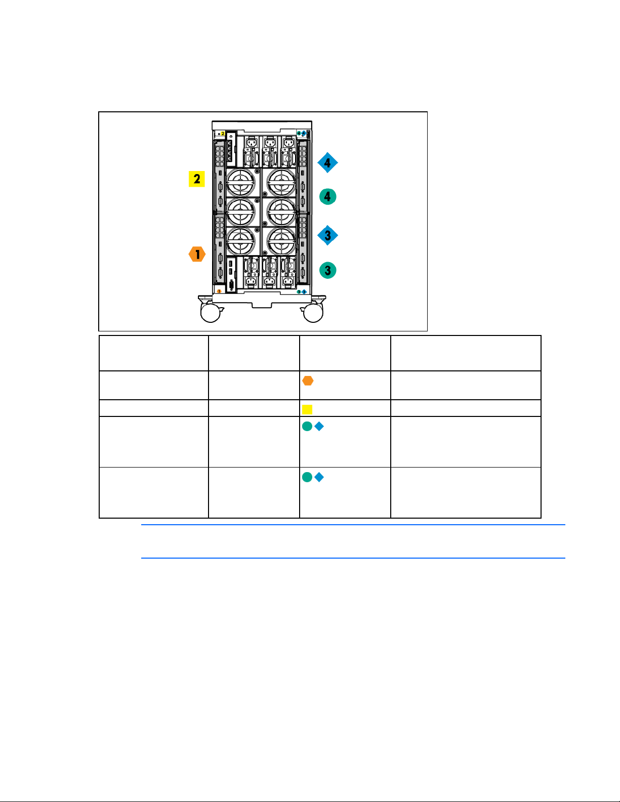
Enclosure front components
Item Description
1 Device bays ("Device bay numbering" on page 11)
2 CD/DVD-ROM drive blank or CD/DVD-ROM drive (optional)
3 Onboard Administrator tray (reserved for future use)
4 Insight Display
5 Onboard Administrator tray containing Onboard
Administrator 1
Device bay numbering
Each enclosure requires interconnects to provide network access for data transfer. Interconnects reside in
bays located on the rear of the enclosure. Be sure to review device bay numbering to determine which
external network connections on the interconnects are active.
IMPORTANT: When looking at the rear of the enclosure, device bay numbering is reversed.
Identifying components and LEDs 11
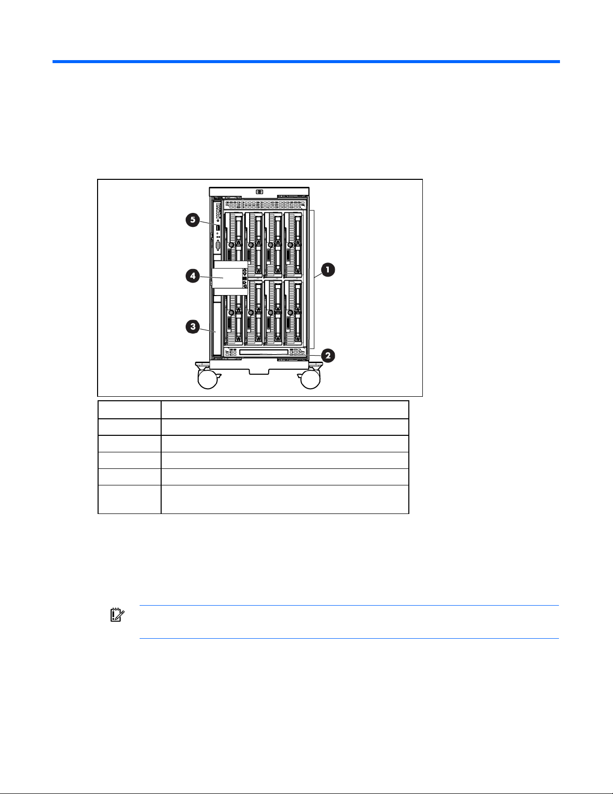
Full-height device bay numbering
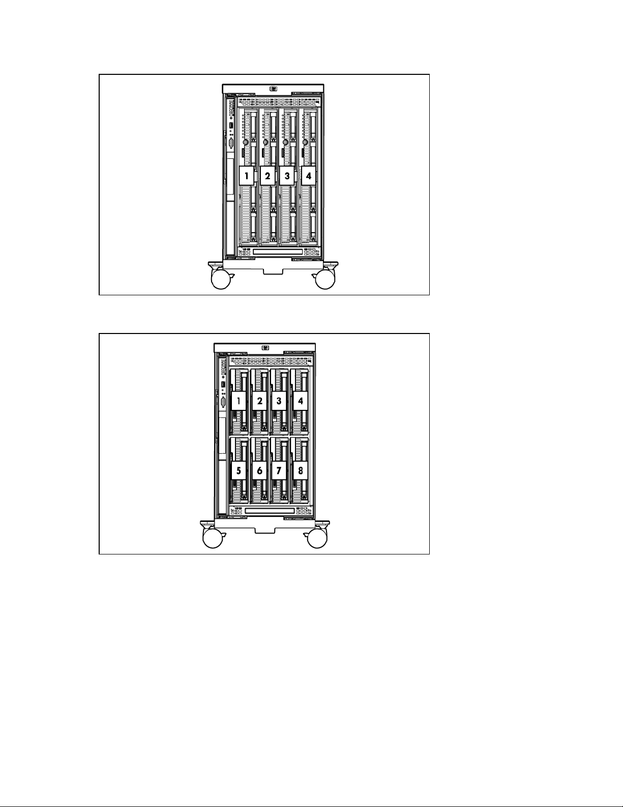
Half-height device bay numbering
Identifying components and LEDs 12
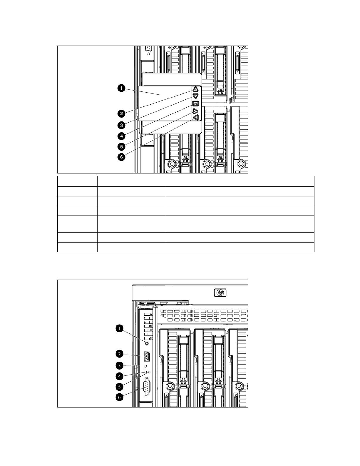
HP BladeSystem Insight Display components
Item Description Function
1 Insight Display screen Displays Main Menu error messages and instructions
2 Up arrow button Moves the menu selection up one position
3 Down arrow button Moves the menu selection down one position
4 OK button Accepts the highlighted selection and navigates to the selected
menu
5 Left arrow button Moves the menu or navigation bar selection left one position
6 Right arrow button Moves the menu or navigation bar selection right one position
HP BladeSystem Onboard Administrator components
Identifying components and LEDs 13
Item Description Status
1 Reset button —
2 USB connector —
3 Health LED Green = Normal
Red = OA firmware issue. See the HP
Onboard Administrator User Guide on the HP
website
(http://www.hp.com/go/bladesystem/docum
entation).
4 Active LED Green = Primary OA module
Off = Standby OA module
5 UID LED Blue = Activated
Off = Deactivated
6 Serial connector —
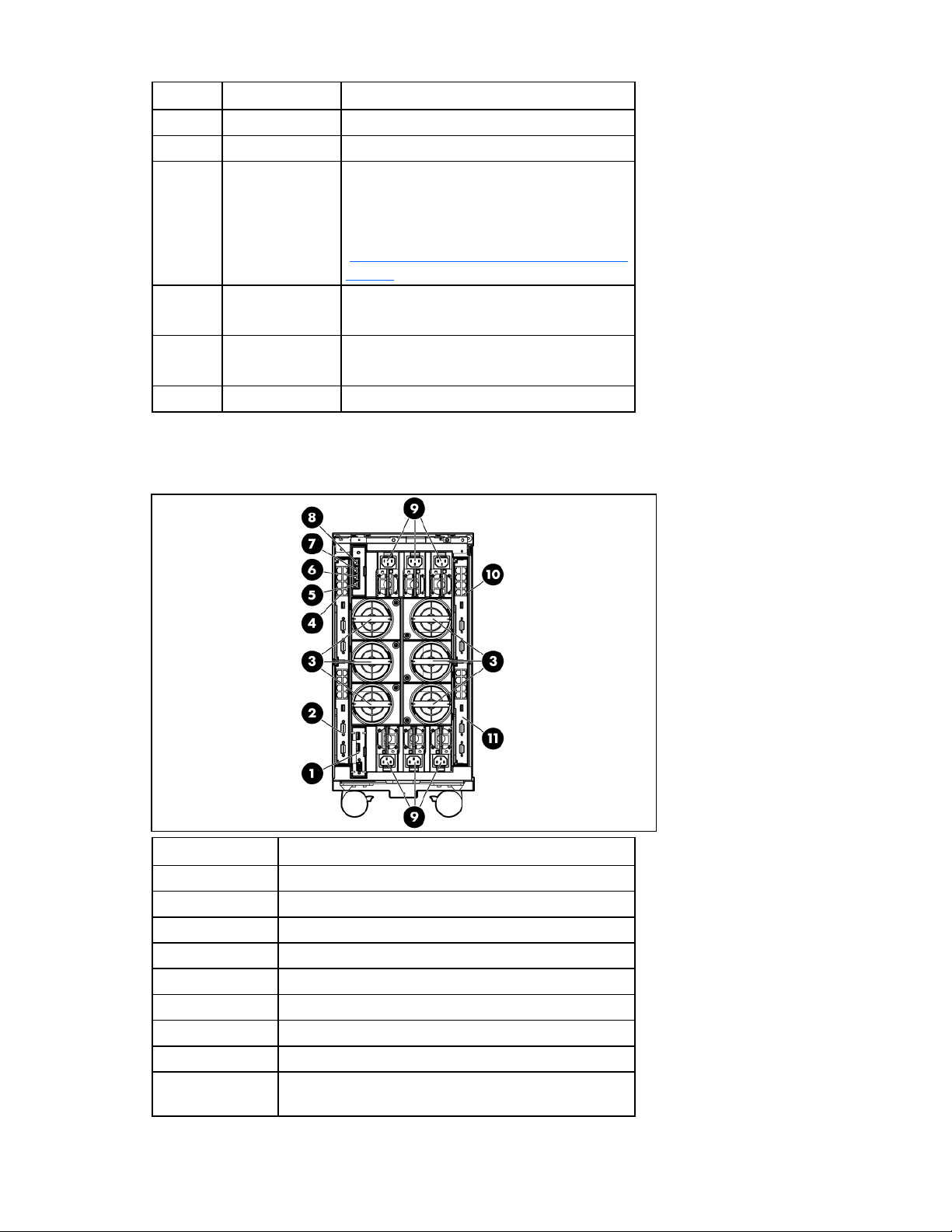
Enclosure rear components
Item Description
1 Reserved for future use
2 Interconnect bay 1
3 Fan bays ("Fan bay numbering" on page 15)
4 Interconnect bay 2
5 Enclosure link-down port
6 Enclosure link-up port
7 Onboard Administrator 1/iLO port
8 Optional KVM module bay
9 Power supply bays ("Power supply bay numbering" on
page 16)
Identifying components and LEDs 14
Item Description
10 Interconnect bay 4
11 Interconnect bay 3
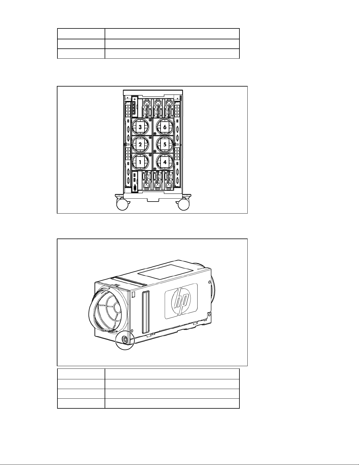
Fan bay numbering
Fan LEDs
LED color Fan status
Solid green The fan is working.
Solid amber The fan has failed.
Flashing amber See the Insight Display screen.
Identifying components and LEDs 15
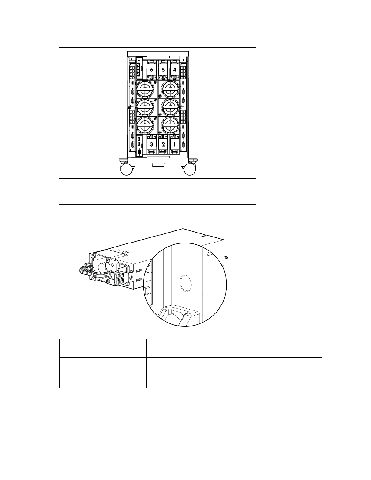
Power supply bay numbering
Power supply LED
Power LED
(green)
Failure LED
(amber)
Status
Off Off No AC power to power supply units
On Off AC present. Standby output on. Power supply DC output on and OK
Off On Power supply failure (includes overvoltage and overtemperature)
Identifying components and LEDs 16
Interconnect bay numbering
To support network connections for specific signals, install the interconnect module in the appropriate
bay.
Server blade signal Interconnect bay
number
NICs 1, 2, 3, and 4
1
Interconnect bay
label
Notes
—
(embedded)
Mezzanine 1 2
Mezzanine 2 3,4
Four port cards connect to bay 2
• Four port cards
• Ports 1 and 3 connect to bay 3
• Ports 2 and 4 connect to bay 4
Mezzanine 3 3,4
• Four port cards
• Ports 1 and 3 connect to bay 3
• Ports 2 and 4 connect to bay 4
NOTE: For information on the location of LEDs and ports on individual interconnect modules,
see the documentation that ships with the interconnect module.
For more information, see "Mapping to interconnect ports (on page 34)."
Identifying components and LEDs 17

Installing components
Setting up the enclosure
1. Select the proper location for the enclosure to be set up based on requirements detailed in "Planning
the installation (on page 5)."
2. Remove the packing materials from the pallet.
WARNING: To reduce the risk of personal injury or damage to the equipment in a rack-free
environment:
• Never stack an enclosure on top of another enclosure.
• Never place equipment on top of an enclosure.
3. Unlock the enclosure wheels.
4. Roll the enclosure down the pallet ramp, and then place it in the location selected in step 1.
5. Lock the enclosure wheels.
• Never place an enclosure on a surface that cannot support up to 153.7 kg (338.9 lb).
Component installation
The following sections contain installation instructions for the individual enclosure components. All
components must be installed and cabled before you power up the enclosure. There is no specific
installation order requirement for the enclosure components.
Installing components 18

Installing a power supply
1. Slide the power supply into the power supply bay until the device locks into place. Repeat this step
for each required power supply.
NOTE: When installing a power supply in power supply bay 1, 2, or 3, orient the power
supply so the plug is positioned toward the bottom of the bay. When installing a power supply
in power supply bay 4, 5, or 6, orient the power supply so the plug is positioned toward the
2. Install power supply blanks in any unused power supply bay.
top of the bay. See "Power supply bay numbering (on page 16)."
Populating power supply bays
For AC redundant (N+N power supplies) configurations, an even number of power supplies is required.
For this configuration, where N is the number of power supplies being used, populate the power supply
bays as shown.
N + N Populate the following power supply bays
1 + 1 1 and 4
2 + 2 1, 2, 4, and 5
3 + 3 Populate all bays
For power supply redundant (N+1 power supplies) configurations, where N is the number of power
supplies being used, populate the power supply bays as shown.
N + 1 Populate the following power supply bays
1 + 1 1 and 4
2 + 1 1, 4, and 2
3 + 1 1, 4, 2, and 5
4 + 1 1, 4, 2, 5, and 3
5 + 1 Populate all bays
Installing components 19
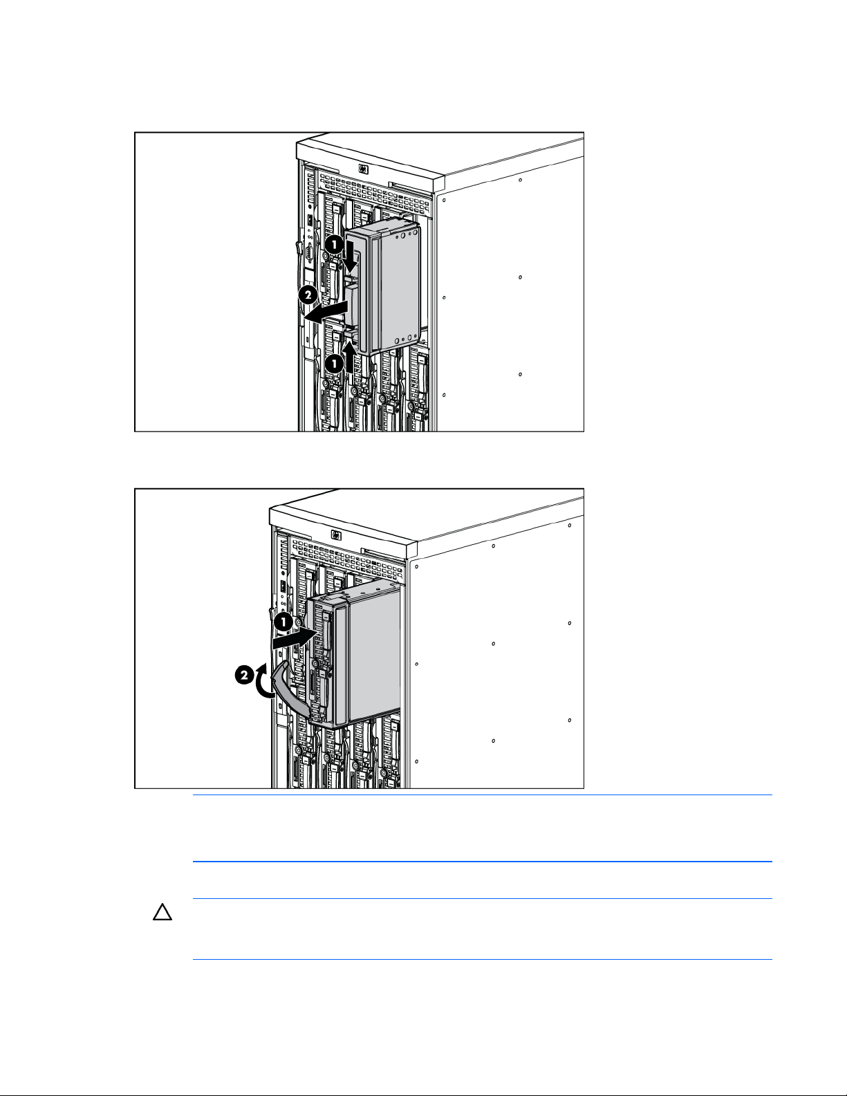
Installing a full-height blade
The enclosure ships with device bay shelves to support half-height devices. To install a full-height device,
remove the device bay shelf and the corresponding blanks.
To install a full-height blade:
1. Remove the blank.
2. Remove the three adjacent blanks.
3. Remove the device bay shelf ("Removing the device bay dividers" on page 22).
4. Remove the connector covers.
Installing components 20
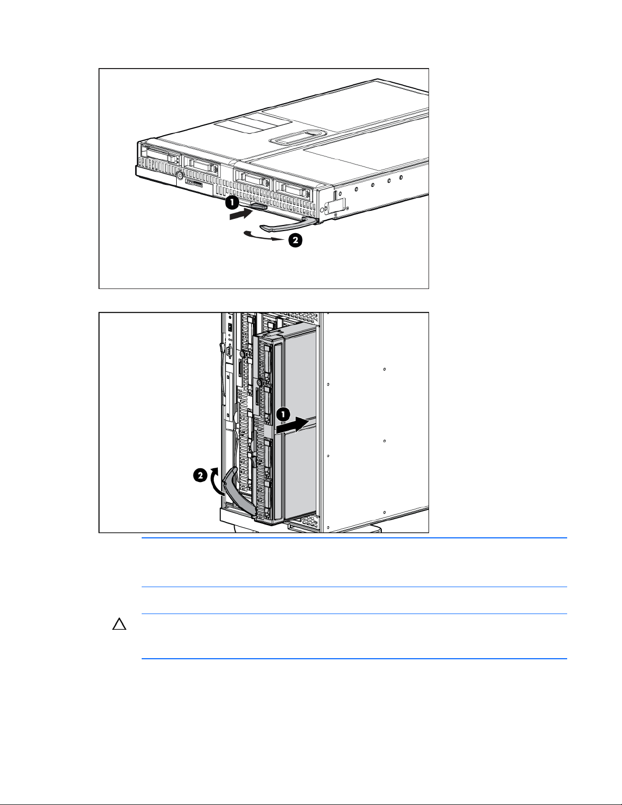
5.
Prepare the blade for installation.
6. Install the blade in the empty bay.
NOTE: If you plan to install four HP Active Cool Fans, you can install up to two full-height
blades. Populate device bay 1 first, then populate device bay 2.
If you plan to install six HP Active Cool Fans, blades can be installed in any configuration.
For more information, see "Installing fans" and "Full-height device bay numbering (on page 12)."
CAUTION: To prevent improper cooling and thermal damage, do not operate the blade or the
enclosure unless all hard drive and device bays are populated with either a component or a
7. Install blanks in any empty bays ("Creating a full-height device bay blank" on page 24).
blank.
Installing components 21
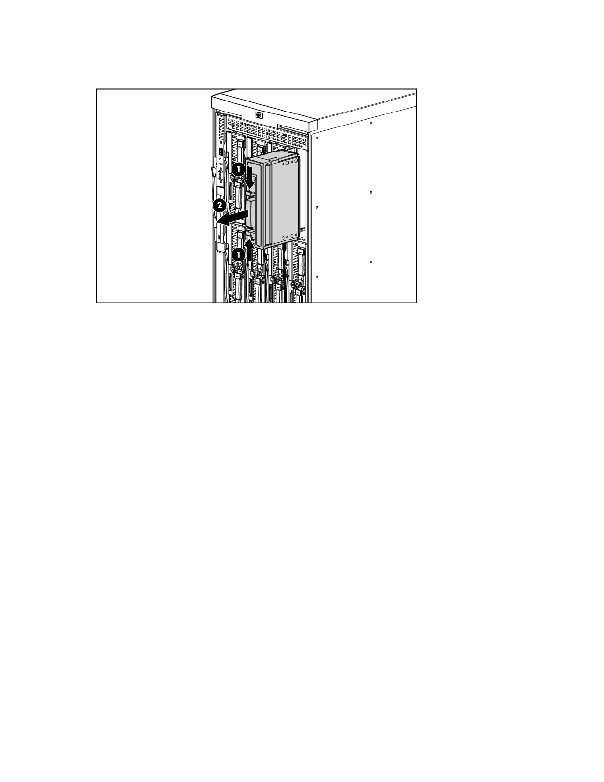
Removing the device bay dividers
1. Remove the blank.
Installing components 22
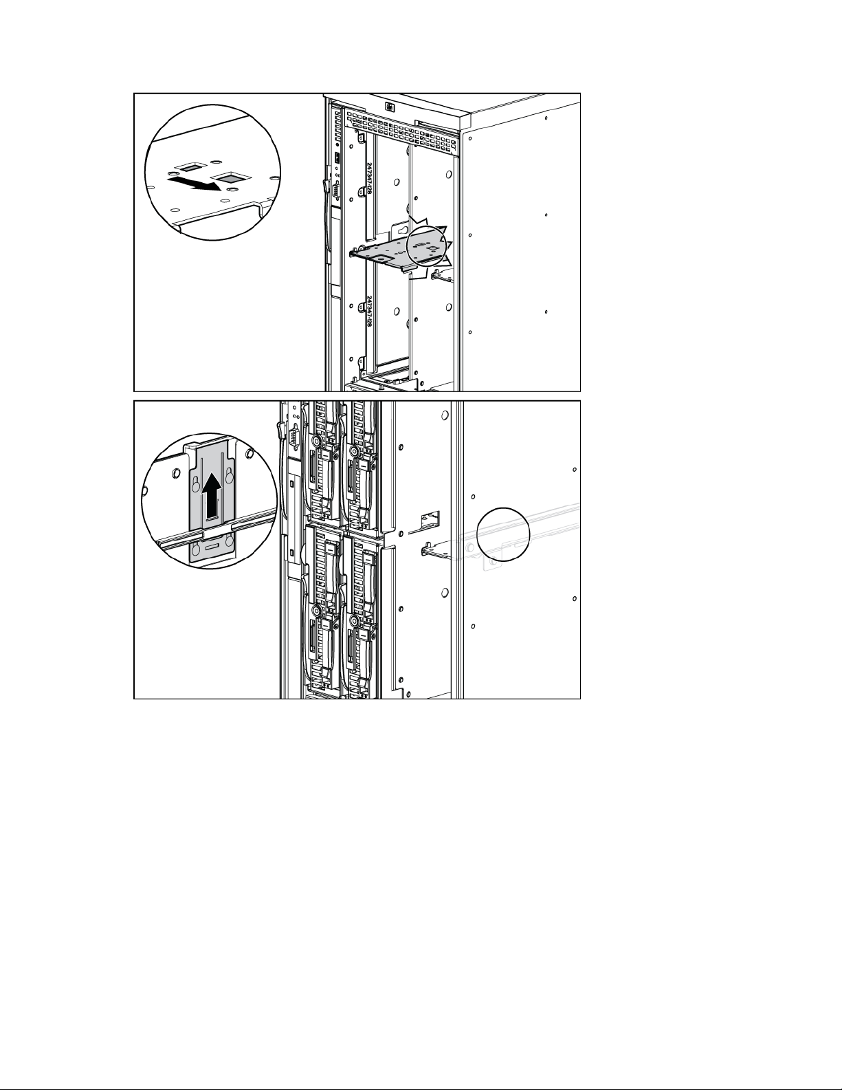
2.
To open the divider locking tab:
Installing components 23
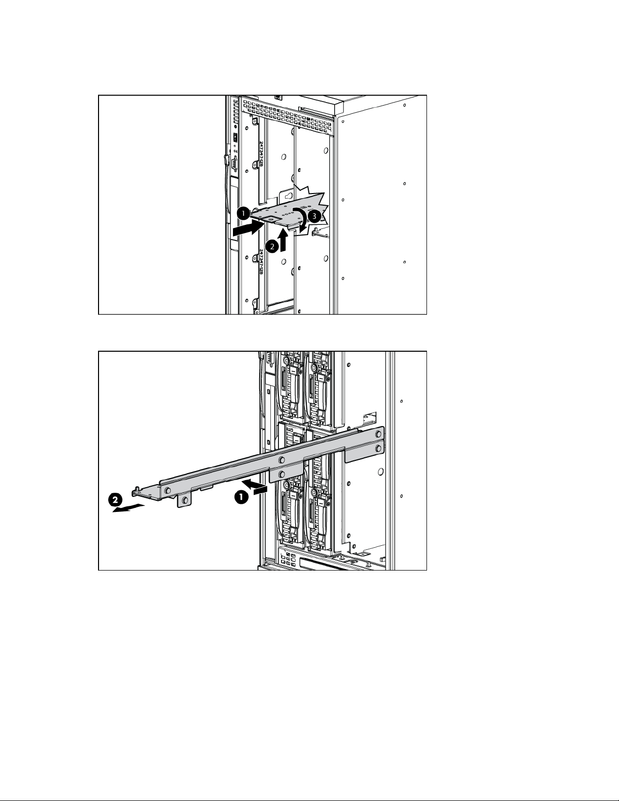
3.
For the half-height divider, push the divider toward the back of the enclosure until the divider stops.
Push the divider up to disengage the tabs from the divider wall, and then rotate the divider
clockwise.
For the mini divider, push the divider toward the back of the enclosure, and then slide it to the left.
Pull the divider out of the chassis.
4. Remove the device bay divider from the enclosure.
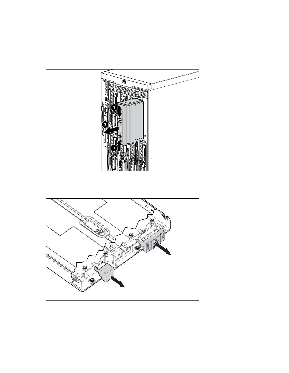
Creating a full-height device bay blank
1. Obtain the coupler plate:
o If you are using a device bay blank that came with the enclosure, the coupler plate can be found
with the contents of the full-height device shipping box.
o If you are using a device bay blank that you purchased as an option, remove the coupler plate
from inside the blank.
Installing components 24

2.
Fit the coupler plate in to the slots on top of the blank, and slide the coupler plate back until it snaps
into place.
3. Fit the slots on the bottom of the second blank on to the tabs on the coupler plate, and slide the
second blank forward until it snaps in place.
4. Install the full-height blank in to the device bay.
Installing components 25
Installing a half-height blade
1. Remove the blank.
2. Install the device bay shelf, if applicable ("Installing dividers" on page 27).
3. Install the blade in the empty bay.
NOTE: If you plan to install four HP Active Cool Fans, you can install up to four half-height
blades. Populate the device bays in the following order: 1, 2, 5, 6.
If you plan to install six HP Active Cool Fans, blades can be installed in any configuration.
For more information, see "Installing fans" and "Half-height device bay numbering (on page 12)."
CAUTION: To prevent improper cooling and thermal damage, do not operate the blade or the
enclosure unless all hard drive and device bays are populated with either a component or a
blank.
4. Install blanks in any empty bays ("Creating a full-height device bay blank" on page 24).
Installing components 26
Loading...