


Errata
Title & Document Type:
Manual Part Number:
Revision Date:
HP References in this Manual
This manual may contain references to HP or Hewlett-Packard. Please note that HewlettPackard's former test and measurement, semiconductor products and chemical analysis businesses are now part of Agilent Technologies. We have made no changes to this manual copy. The HP XXXX referred to in this document is now the Agilent XXXX. For example, model number HP8648A is now model number Agilent 8648A.
About this Manual
We’ve added this manual to the Agilent website in an effort to help you support your product. This manual provides the best information we could find. It may be incomplete or contain dated information, and the scan quality may not be ideal. If we find a better copy in the future, we will add it to the Agilent website.
Support for Your Product
Agilent no longer sells or supports this product. You will find any other available product information on the Agilent Test & Measurement website:
www.tm.agilent.com
Search for the model number of this product, and the resulting product page will guide you to any available information. Our service centers may be able to perform calibration if no repair parts are needed, but no other support from Agilent is available.

HP 4338B Milliohmmeter
Operation Manual
SERIAL NUMBERS
This manual applies directly to instruments with serial number pre x JP1KD, or rmware revision 1.01. For additional important information about serial numbers, read \Serial Number" in Appendix A.
HP Part No. 04338-90030
Printed in Japan June 1998
Third Edition

Notice
The information contained in this document is subject to change without notice.
This document contains proprietary information that is protected by copyright. All rights are reserved. No part of this document may be photocopied, reproduced, or translated to another language without the prior written consent of the Hewlett-Packard Company.
Hewlett-Packard Japan, LTD.
Kobe Instrument Division
1-3-2, Murotani, Nishi-Ku, Kobe-shi,
Hyogo, 651-2241 Japan
c Copyright 1996,1997,1998 Hewlett-Packard Japan, Ltd.

HP 4338B
Manual Printing History
The manual's printing date and part number indicate its current edition. The printing date changes when a new edition is printed. (Minor corrections and updates that are incorporated at reprint do not cause the date to change.) The manual part number changes when extensive technical changes are incorporated.
March 1996 : : : : : : : : : : : : : : : : : : : : : : : : : : : : : : : : : : : : : : : : : : : : : : : : : : : : : : : : : : : : : : : : : : : : : : : : : |
First Edition |
April 1997 : : : : : : : : : : : : : : : : : : : : : : : : : : : : : : : : : : : : : : : : : : : : : : : : : : : : : : : : : : : : : : : : : : : : : : : : |
Second Edition |
June 1998 : : : : : : : : : : : : : : : : : : : : : : : : : : : : : : : : : : : : : : : : : : : : : : : : : : : : : : : : : : : : : : : : : : : : : : : : : : |
Third Edition |
iii

HP 4338B
Safety Summary
The following general safety precautions must be observed during all phases of operation, service, and repair of this instrument. Failure to comply with these precautions or with speci c WARNINGS elsewhere in this manual may impair the protection provided by the equipment. In addition it violates safety standards of design, manufacture, and intended use of the instrument.
The Hewlett-Packard Company assumes no liability for the customer's failure to comply with these requirements.
Note |
HP 4338B comply with INSTALLATION CATEGORY II and POLLUTION |
|
DEGREE 2 in IEC1010-1. HP 4338B are INDOOR USE product. |
|
|
|
|
Note |
LEDs in HP 4338B are Class 1 in accordance with IEC825-1. |
|
CLASS 1 LED PRODUCT |
Ground The Instrument
To avoid electric shock hazard, the instrument chassis and cabinet must be connected to a safety earth ground by the supplied power cable with earth blade.
DO NOT Operate In An Explosive Atmosphere
Do not operate the instrument in the presence of ammable gasses or fumes. Operation of any electrical instrument in such an environment constitutes a de nite safety hazard.
Keep Away From Live Circuits
Operating personnel must not remove instrument covers. Component replacement and internal adjustments must be made by quali ed maintenance personnel. Do not replace components with the power cable connected. Under certain conditions, dangerous voltages may exist even with the power cable removed. To avoid injuries, always disconnect power and discharge circuits before touching them.
DO NOT Service Or A djust Alone
Do not attempt internal service or adjustment unless another person, capable of rendering rst aid and resuscitation, is present.
DO NOT Substitute P arts Or Modify Instrument
Because of the danger of introducing additional hazards, do not install substitute parts or perform unauthorized modi cations to the instrument. Return the instrument to a
Hewlett-Packard Sales and Service O ce for service and repair to ensure that safety features are maintained.
iv

HP 4338B
Dangerous Procedure W arnings
Warnings , such as the example below, precede potentially dangerous procedures throughout this manual. Instructions contained in the warnings must be followed.
Warning |
Dangerous voltages, capable of causing death, are present in this |
|
instrument. Use extreme caution when handling, testing, and adjusting |
|
this instrument. |
|
|
Safety Symbols
General de nitions of safety symbols used on equipment or in manuals are listed below.
Instruction manual symbol: the product is marked with this symbol when it is necessary for the user to refer to the instruction manual.
Alternating current.
Direct current.
On (Supply).
O (Supply).
In position of push-button switch.
Out position of push-button switch.
Frame (or chassis) terminal. A connection to the frame (chassis) of the equipment which normally include all exposed metal structures.
sign denotes a hazard. It calls attention to a procedure, practice, condition or the like, which, if not correctly performed or adhered to, could result in injury or death to personnel.
sign denotes a hazard. It calls attention to a procedure, practice, condition or the like, which, if not correctly performed or adhered to, could result in damage to or destruction of part or all of the product.
sigh denotes important information. It calls attention to a procedure, practice, condition or the like, which is essential to highlight.
A xed to product containing static sensitive devices use anti-static handling procedures to prevent electrostatic discharge damage to component.
v

HP 4338B
Certi cation
Hewlett-Packard Company certi es that this product met its published speci cations at the time of shipment from the factory. Hewlett-Packard further certi es that its calibration measurements are traceable to the United States National Institute of Standards and Technology, to the extent allowed by the Institution's calibration facility, or to the calibration facilities of other International Standards Organization members.
Warranty
This Hewlett-Packard instrument product is warranted against defects in material and workmanship for a period of one year from the date of shipment, except that in the case of certain components listed in General Information of this manual, the warranty shall be for the speci ed period. During the warranty period, Hewlett-Packard Company will, at its option, either repair or replace products that prove to be defective.
For warranty service or repair, this product must be returned to a service facility designated by HP. Buyer shall prepay shipping charges to HP and HP shall pay shipping charges to return the product to Buyer. However, Buyer shall pay all shipping charges, duties, and taxes for products returned to HP from another country.
HP warrants that its software and rmware designated by HP for use with an instrument will execute its programming instruction when property installed on that instrument. HP does not warrant that the operation of the instrument, or software, or rmware will be uninterrupted or error free.
Limitation Of Warranty
The foregoing warranty shall not apply to defects resulting from improper or inadequate maintenance by Buyer, Buyer-supplied software or interfacing, unauthorized modi cation or misuse, operation outside the environmental speci cations for the product, or improper site preparation or maintenance.
No other warranty is expressed or implied. HP speci cally disclaims the implied warranties of merchantability and tness for a particular purpose.
vi

HP 4338B
Exclusive Remedies
The remedies provided herein are buyer's sole and exclusive remedies. HP shall not be liable for any direct, indirect, special, incidental, or consequential damages, whether based on contract, tort, or any other legal theory.
Assistance
Product maintenance agreements and other customer assistance agreements are available for Hewlett-Packard products.
For any assistance, contact your nearest Hewlett-Packard Sales and Service O ce. Addresses are provided at the back of this manual.
vii

|
|
|
HP 4338B |
|
|
|
|
Typeface Conventions |
|||
Bold |
Boldface type is used when a term is de ned. For example: icons are |
||
|
|
|
symbols. |
Italics |
Italic type is used for emphasis and for titles of manuals and other |
||
|
|
|
publications. |
|
|
|
Italic type is also used for keyboard entries when a name or a variable |
|
|
|
must be typed in place of the words in italics. For example: copy |
|
|
|
lename means to type the word copy, to type a space, and then to |
|
|
|
type the name of a le such as file1 . |
Computer |
Computer font is used for on-screen prompts and messages. |
||
4 |
|
5 |
Labeled keys on the instrument front panel are enclosed in 4 5. |
HARDKEYS |
|||
SOFTKEYS |
Softkeys located to the right of the CRT are enclosed in . |
||
viii

Contents
1. Getting Started
Introduction . . . . . . . . . . . . . . . . . . . . . . . . . . . . . . . . . |
1-1 |
Overview . . . . . . . . . . . . . . . . . . . . . . . . . . . . . . . . . . |
1-2 |
Features . . . . . . . . . . . . . . . . . . . . . . . . . . . . . . . . . |
1-2 |
Accessories Available . . . . . . . . . . . . . . . . . . . . . . . . . . . . |
1-3 |
Front Panel . . . . . . . . . . . . . . . . . . . . . . . . . . . . . . . . |
1-4 |
Display . . . . . . . . . . . . . . . . . . . . . . . . . . . . . . . . . . |
1-7 |
Rear Panel . . . . . . . . . . . . . . . . . . . . . . . . . . . . . . . . |
1-8 |
Incoming Inspection . . . . . . . . . . . . . . . . . . . . . . . . . . . . . |
1-9 |
Ventilation Requirements . . . . . . . . . . . . . . . . . . . . . . . . . . . |
1-9 |
Instruction for Cleaning . . . . . . . . . . . . . . . . . . . . . . . . . . . |
1-9 |
Power Cable . . . . . . . . . . . . . . . . . . . . . . . . . . . . . . . . . |
1-10 |
Preparation for Use . . . . . . . . . . . . . . . . . . . . . . . . . . . . . |
1-12 |
Power Requirements . . . . . . . . . . . . . . . . . . . . . . . . . . . . |
1-12 |
Fuse . . . . . . . . . . . . . . . . . . . . . . . . . . . . . . . . . |
1-12 |
Turning ON the HP 4338B . . . . . . . . . . . . . . . . . . . . . . . . . |
1-13 |
Using Front-Panel Keys . . . . . . . . . . . . . . . . . . . . . . . . . . . |
1-14 |
Direct Execution Keys . . . . . . . . . . . . . . . . . . . . . . . . . . . |
1-14 |
Toggle Keys . . . . . . . . . . . . . . . . . . . . . . . . . . . . . . . . |
1-14 |
Selection Keys . . . . . . . . . . . . . . . . . . . . . . . . . . . . . . . |
1-14 |
Value Setup Keys . . . . . . . . . . . . . . . . . . . . . . . . . . . . . |
1-15 |
Numeric Keys . . . . . . . . . . . . . . . . . . . . . . . . . . . . . . |
1-15 |
Maximum and Minimum Keys . . . . . . . . . . . . . . . . . . . . . . |
1-16 |
Left/Down and Right/Up Arrow Keys . . . . . . . . . . . . . . . . . . . |
1-17 |
Back Space Key . . . . . . . . . . . . . . . . . . . . . . . . . . . . . |
1-17 |
To Perform a Measurement . . . . . . . . . . . . . . . . . . . . . . . |
1-18 |
Connecting a Test Fixture . . . . . . . . . . . . . . . . . . . . . . . . . . |
1-19 |
Using the HP 16338A . . . . . . . . . . . . . . . . . . . . . . . . . . . |
1-19 |
To Reset HP 4338B . . . . . . . . . . . . . . . . . . . . . . . . . . . . . . |
1-20 |
To Perform a SHORT Correction . . . . . . . . . . . . . . . . . . . . . . . . |
1-20 |
To Select Measurement Parameter . . . . . . . . . . . . . . . . . . . . . . |
1-22 |
To Select Auto Measurement Mode . . . . . . . . . . . . . . . . . . . . . . |
1-22 |
To Select Test Signal Level . . . . . . . . . . . . . . . . . . . . . . . . . . |
1-22 |
To Select Measurement Range . . . . . . . . . . . . . . . . . . . . . . . . |
1-23 |
Auto / Hold Range Mode . . . . . . . . . . . . . . . . . . . . . . . . . . |
1-23 |
Measurement Range Setting . . . . . . . . . . . . . . . . . . . . . . . . |
1-23 |
Contents-1
2. Operating the HP 4338B
Introduction . . . . . . . . . . . . . . . . . . . . . . . . . . . . . . . . . |
2-1 |
Measurement Con guration . . . . . . . . . . . . . . . . . . . . . . . . . |
2-2 |
To Select the Measurement Time Mode . . . . . . . . . . . . . . . . . . . |
2-2 |
To Set the Averaging Rate . . . . . . . . . . . . . . . . . . . . . . . . . |
2-2 |
To Set the Trigger Delay or Source Delay Time . . . . . . . . . . . . . . . . |
2-2 |
To Set the Contact Check . . . . . . . . . . . . . . . . . . . . . . . . . . |
2-3 |
To Set the Beeper Mode . . . . . . . . . . . . . . . . . . . . . . . . . . |
2-4 |
To Save and Recall Instrument Settings . . . . . . . . . . . . . . . . . . . |
2-4 |
Making a Measurement . . . . . . . . . . . . . . . . . . . . . . . . . . . . |
2-6 |
To Trigger a Measurement . . . . . . . . . . . . . . . . . . . . . . . . . |
2-6 |
To Use the Comparator Function . . . . . . . . . . . . . . . . . . . . . . |
2-7 |
To Display Deviation Data . . . . . . . . . . . . . . . . . . . . . . . . . |
2-8 |
To Set the Reference Value . . . . . . . . . . . . . . . . . . . . . . . . |
2-8 |
To Select the Deviation Display Mode . . . . . . . . . . . . . . . . . . . |
2-9 |
To Set the Display Mode and Display Digits . . . . . . . . . . . . . . . . . |
2-10 |
To Change the Measurement Settings Display Mode . . . . . . . . . . . . . |
2-11 |
To Lock Out the Front Panel Keys . . . . . . . . . . . . . . . . . . . . . |
2-12 |
To Select the Local Mode . . . . . . . . . . . . . . . . . . . . . . . . . . |
2-12 |
To Set the HP-IB Address . . . . . . . . . . . . . . . . . . . . . . . . . . |
2-12 |
To Print Measurement Data . . . . . . . . . . . . . . . . . . . . . . . . . |
2-12 |
To Test the HP 4338B . . . . . . . . . . . . . . . . . . . . . . . . . . . . |
2-13 |
To Perform a Self-Test . . . . . . . . . . . . . . . . . . . . . . . . . . . |
2-13 |
To Test the Front Panel Keys' Functionality . . . . . . . . . . . . . . . . . |
2-13 |
If You Have a Problem . . . . . . . . . . . . . . . . . . . . . . . . . . . . |
2-14 |
If the Display is Blank and the HP 4338B Appears Dead . . . . . . . . . . . |
2-14 |
If an Error Message is Displayed . . . . . . . . . . . . . . . . . . . . . . |
2-14 |
If the HP 4338B does not Accept Any Key Input . . . . . . . . . . . . . . . |
2-14 |
3.Function Reference
Introduction . . . . . . . . . . . . . . . . . . . . . . . . . . . . . . . . . |
3-1 |
|||
Front Panel . . . . . . . . . . . . . . . . . . . . . . . . . . . . . . . . . |
3-2 |
|||
Display . . . . . . . . . . . . . . . . . . . . . . . . . . . . . . . . . . |
3-2 |
|||
LINE Switch . . . . . . . . . . . . . . . . . . . . . . . . . . . . . . . . |
3-3 |
|||
Chassis Terminal . . . . . . . . . . . . . . . . . . . . . . . . . . . . . . |
3-3 |
|||
UNKNOWN Terminals . . . . . . . . . . . . . . . . . . . . . . . . . |
3-3 |
|||
Auto Measurement Key |
|
. . . . . . . . . . . . . . . . . . . . . . . . |
3-3 |
|
Level Key |
. . . . . . . . . . . . . . . . . . . . . . . . . . . . . . |
3-4 |
||
Measurement Parameter Key |
. . . . . . . . . . . . . . . . . . . . . |
3-5 |
||
Deviation Mode Key |
|
. . . . . . . . . . . . . . . . . . . . . . . |
3-5 |
|
Measurement Time Key |
|
. . . . . . . . . . . . . . . . . . . . . . . . |
3-5 |
|
Show Setting Key |
. . . . . . . . . . . . . . . . . . . . . . . . . . . |
3-5 |
||
Display Mode Key |
|
. . . . . . . . . . . . . . . . . . . . . . . . |
3-6 |
|
Average Key |
. . . . . . . . . . . . . . . . . . . . . . . . . . . . . |
3-6 |
||
Auto / Hold range Key |
|
. . . . . . . . . . . . . . . . . . . . . . . . |
3-6 |
|
Range Setup Key |
|
. . . . . . . . . . . . . . . . . . . . . . . . . |
3-6 |
|
Trigger Key |
. . . . . . . . . . . . . . . . . . . . . . . . . . . . . . |
3-6 |
||
Trigger Mode Key |
. . . . . . . . . . . . . . . . . . . . . . . . . . . |
3-7 |
||
Delay Key |
. . . . . . . . . . . . . . . . . . . . . . . . . . . . . |
3-7 |
||
Contents-2

Local Key |
. . . . . . . . . . . . . . . . . . . . . . . . . . . . . . . |
3-8 |
||||
Address Key |
|
. . . . . . . . . . . . . . . . . . . . . . . . . . . . |
3-8 |
|||
Save Key |
|
. . . . . . . . . . . . . . . . . . . . . . . . . . . . . |
3-8 |
|||
Recall Key |
. . . . . . . . . . . . . . . . . . . . . . . . . . . . . . |
3-9 |
||||
Primary and Secondary comparator limit Key |
. . . . . . . . . . . . |
3-9 |
||||
Left/Down Arrow Key and Right/Up Arrow Key |
. . . . . . . . . . |
3-9 |
||||
0, 1, . . . , 9, 0(minus), .(point) Key |
. . . |
. . . . . . . . . |
3-9 |
|||
Enter Key |
. . . . . . . . . . . . . . . . . . . . . . . . . . . . . . . |
3-9 |
||||
BLUE Shift Key |
. . . . . . . . . . . . . . . . . . . . . . . . . . . . |
3-9 |
||||
Engineering units Key |
. . . . . . . . . . . . . . . . . . . . . . . . . |
3-10 |
||||
Back Space Key |
. . . . . . . . . . . . . . . . . . . . . . . . . . . . |
3-10 |
||||
Minimum Key |
|
|
. . . . . . . . . . . . . . . . . . . . . . . . . . . |
3-10 |
||
Maximum Key |
|
|
. . . . . . . . . . . . . . . . . . . . . . . . . . . |
3-10 |
||
Comparator Key |
|
. . . . . . . . . . . . . . . . . . . . . . . . . . |
3-10 |
|||
Contact Check Key |
|
. . . . . . . . . . . . . . . . . . . . . . . . |
3-11 |
|||
Short Key |
|
. . . . . . . . . . . . . . . . . . . . . . . . . . . . . |
3-11 |
|||
Key Lock Key |
|
|
. . . . . . . . . . . . . . . . . . . . . . . . . . . |
3-11 |
||
Reset Key |
|
. . . . . . . . . . . . . . . . . . . . . . . . . . . . . |
3-12 |
|||
Con guration Key |
|
. . . . . . . . . . . . . . . . . . . . . . . . . |
3-12 |
|||
Rear Panel . . . . . . . . . . . . . . . . . . . . . . . . . . . . . . . . . |
3-14 |
|||||
Trigger . . . . . . . . . . . . . . . . . . . . . . . . . . . . . . |
3-14 |
|||||
LINE Fuse Holder . . . . . . . . . . . . . . . . . . . . . . . . . . |
3-15 |
|||||
LINE Voltage Selector . . . . . . . . . . . . . . . . . . . . . . . . . . . |
3-15 |
|||||
Serial Number Plate . . . . . . . . . . . . . . . . . . . . . . . . . . . . |
3-15 |
|||||
Power Cord Receptacle . . . . . . . . . . . . . . . . . . . . . . . . . . . |
3-15 |
|||||
Power Code . . . . . . . . . . . . . . . . . . . . . . . . . . . . . . . |
3-15 |
|||||
Handler Interface . . . . . . . . . . . . . . . . . . . . . . . . . . . . . |
3-16 |
|||||
Speci cation . . . . . . . . . . . . . . . . . . . . . . . . . . . . . . . |
3-16 |
|||||
HP-IB Interface . . . . . . . . . . . . . . . . . . . . . . . . . . . . . . |
3-18 |
|||||
Theory of Operation . . . . . . . . . . . . . . . . . . . . . . . . . . . . . |
3-20 |
|||||
Overall Measurement Theory . . . . . . . . . . . . . . . . . . . . . . . . |
3-20 |
|||||
Test Signal Level . . . . . . . . . . . . . . . . . . . . . . . . . . . . . . |
3-22 |
|||||
Actual Signal Level across DUT . . . . . . . . . . . . . . . . . . . . . . |
3-22 |
|||||
Limitation of Test Level . . . . . . . . . . . . . . . . . . . . . . . . . |
3-22 |
|||||
4. Remote Operation
Introduction . . . . . . . . . . . . . . . . . . . . . . . . . . . . . . . . . |
4-1 |
Getting Started . . . . . . . . . . . . . . . . . . . . . . . . . . . . . . . |
4-2 |
Input/Output Statements . . . . . . . . . . . . . . . . . . . . . . . . . . |
4-2 |
Reading the HP-IB Address . . . . . . . . . . . . . . . . . . . . . . . . . |
4-2 |
Sending a Remote Command . . . . . . . . . . . . . . . . . . . . . . . . |
4-2 |
Returning to the Local Mode . . . . . . . . . . . . . . . . . . . . . . . . |
4-3 |
Query Commands . . . . . . . . . . . . . . . . . . . . . . . . . . . . . |
4-3 |
Getting Data from the HP 4338B . . . . . . . . . . . . . . . . . . . . . . |
4-3 |
To Control the HP 4338B from an External Computer . . . . . . . . . . . . |
4-4 |
To Set Up the HP 4338B . . . . . . . . . . . . . . . . . . . . . . . . . . . |
4-5 |
To Reset the HP 4338B . . . . . . . . . . . . . . . . . . . . . . . . . . . |
4-5 |
Contents-3
To Set the LINE Frequency . . . . . . . . . . . . . . . . . . . . . . . . . |
4-5 |
To Perform the SHORT Correction . . . . . . . . . . . . . . . . . . . . . |
4-5 |
To Select the Measurement Parameter . . . . . . . . . . . . . . . . . . . |
4-5 |
To Select the Auto Measurement Mode . . . . . . . . . . . . . . . . . . |
4-6 |
To Select the Measurement Range . . . . . . . . . . . . . . . . . . . . . |
4-6 |
To Select the Test Signal Level . . . . . . . . . . . . . . . . . . . . . . |
4-6 |
To Set the Measurement Time Mode . . . . . . . . . . . . . . . . . . . . |
4-6 |
To Set the Averaging Rate . . . . . . . . . . . . . . . . . . . . . . . . |
4-7 |
To Set the Delay Time . . . . . . . . . . . . . . . . . . . . . . . . . . |
4-7 |
To Set the Beeper Mode . . . . . . . . . . . . . . . . . . . . . . . . . |
4-7 |
To Use Comparator Function . . . . . . . . . . . . . . . . . . . . . . . . |
4-8 |
To Display a Deviation Measurement . . . . . . . . . . . . . . . . . . . . |
4-8 |
To Wait Until Previously Sent Commands are Completed . . . . . . . . . . . |
4-8 |
To Get the Current Instrument Settings . . . . . . . . . . . . . . . . . . . |
4-9 |
To Save and Recall Instrument Settings . . . . . . . . . . . . . . . . . . . |
4-9 |
To Trigger a Measurement . . . . . . . . . . . . . . . . . . . . . . . . . . |
4-10 |
To Retrieve Data E ciently . . . . . . . . . . . . . . . . . . . . . . . . . |
4-12 |
To Transfer Data Using the Real Data Format . . . . . . . . . . . . . . . . |
4-12 |
To Use a Data Bu er . . . . . . . . . . . . . . . . . . . . . . . . . . . . |
4-12 |
Other Features . . . . . . . . . . . . . . . . . . . . . . . . . . . . . . . |
4-13 |
To test the HP 4338B . . . . . . . . . . . . . . . . . . . . . . . . . . . . |
4-13 |
To Report the Instrument's Status . . . . . . . . . . . . . . . . . . . . . . |
4-13 |
If You Have a Problem . . . . . . . . . . . . . . . . . . . . . . . . . . . . |
4-15 |
If the HP 4338B Hangs Up When You Send ABORt Command . . . . . . . . . |
4-15 |
5. HP-IB Reference
Introduction . . . . . . . . . . . . . . . . . . . . . . . . . . . . . . . . . |
5-1 |
||
HP-IB Commands . . . . . . . . . . . . . . . . . . . . . . . . . . . . . . |
5-1 |
||
Common Commands . . . . . . . . . . . . . . . . . . . . . . . . . . . . |
5-1 |
||
Subsystem Commands . . . . . . . . . . . . . . . . . . . . . . . . . . . |
5-1 |
||
Subsystem Command Tree . . . . . . . . . . . . . . . . . . . . . . . . . . |
5-4 |
||
Program Message Syntax . . . . . . . . . . . . . . . . . . . . . . . . . . . |
5-5 |
||
Case . . . . . . . . . . . . . . . . . . . . . . . . . . . . . . . . . . . |
5-5 |
||
Program Message Terminator . . . . . . . . . . . . . . . . . . . . . . . . |
5-5 |
||
Subsystem Command Syntax . . . . . . . . . . . . . . . . . . . . . . . . |
5-5 |
||
Common Command Syntax . . . . . . . . . . . . . . . . . . . . . . . . . |
5-5 |
||
Parameters . . . . . . . . . . . . . . . . . . . . . . . . . . . . . . . . |
5-5 |
||
Parameter Types . . . . . . . . . . . . . . . . . . . . . . . . . . . . . |
5-5 |
||
Su x . . . . . . . . . . . . . . . . . . . . . . . . . . . . . . . . . . |
5-6 |
||
Multiple Messages . . . . . . . . . . . . . . . . . . . . . . . . . . . . . |
5-7 |
||
Query and Response Message Syntax . . . . . . . . . . . . . . . . . . . . |
5-7 |
||
Command Reference . . . . . . . . . . . . . . . . . . . . . . . . . . . . . |
5-8 |
||
Notations . . . . . . . . . . . . . . . . . . . . . . . . . . . . . . . . . |
5-8 |
||
ABORt Command . . . . . . . . . . . . . . . . . . . . . . . . . . . . . . |
5-9 |
||
:ABORt . . . . . . . . . . . . . . . . . . . . . . . . . . . . . . . . . . |
5-9 |
||
CALCulate Subsystem . . . . . . . . . . . . . . . . . . . . . . . . . . . . |
5-10 |
||
:CALCulate1:FORMat f REAL j MLINear g |
|
||
:CALCulate2:FORMat f NONE j IMAGnary j PHASe j LS g . . . . . . . . |
5-11 |
||
:CALCulatef1j2g:LIMit:BEEPer:CONDition f FAIL j PASS g . . . . . . . . . . |
5-11 |
||
:CALCulatef1j2g:LIMit:BEEPer[:STATe] f ON j OFF j 1 j 0 g . . . . . . . . . . |
5-12 |
||
:CALCulatef1j2g:LIMit:CLEar . . . . . . . . . . . . . . . . . . . . . . . . |
5-12 |
||
:CALCulatef1j2g:LIMit:FAIL? . . . . . . . . . . . . . . . . . . . . . . . . |
5-12 |
||
:CALCulatef1j2g:LIMit:LOWer[:DATA] <numeric |
|
value> . . . . . . . . . . . |
5-12 |
|
|||
:CALCulatef1j2g:LIMit:LOWer:STATe f ON j OFF j 1 j 0 g . . . . . . . . . . . |
5-13 |
||
:CALCulatef1j2g:LIMit:STATe f ON j OFF j 1 j 0 g . . . . . . . . . . . . . . |
5-13 |
||
Contents-4
:CALCulatef1j2g:LIMit:UPPer[:DATA] <numeric |
|
|
value> . . . . . . . . . . . |
5-13 |
|||||||||||||||||||||
|
|
||||||||||||||||||||||||
:CALCulatef1j2g:LIMit:UPPer:STATe f ON j OFF j 1 j 0 g . . . . . . . . . . . |
5-13 |
||||||||||||||||||||||||
:CALCulatef1j2g:MATH:EXPRession:CATalog? . . . . . . . . . . . . . . . . |
5-13 |
||||||||||||||||||||||||
:CALCulatef1j2g:MATH:EXPRession:NAME f DEV j PCNT g . . . . . . . . . |
5-14 |
||||||||||||||||||||||||
:CALCulatef1j2g:MATH:STATe f ON j OFF j 1 j 0 g . . . . . . . . . . . . . . |
5-14 |
||||||||||||||||||||||||
:CALCulatef1j2g:PATH? . . . . . . . . . . . . . . . . . . . . . . . . . . |
5-14 |
||||||||||||||||||||||||
DATA Subsystem . . . . . . . . . . . . . . . . . . . . . . . . . . . . . . . |
5-15 |
||||||||||||||||||||||||
:DATA[:DATA] f REF1 j REF2 g,<numeric |
|
|
|
|
value> . . . . . . . . . . . . . . |
5-15 |
|||||||||||||||||||
|
|
|
|||||||||||||||||||||||
:DATA[:DATA]? f BUF1 j BUF2 g . . . . . . . . . . . . . . . . . . . . . . |
5-16 |
||||||||||||||||||||||||
:DATA:FEED f BUF1 j BUF2 g,<data |
|
|
handle> . . . . . . . . . . . . . . . |
5-16 |
|||||||||||||||||||||
|
|
||||||||||||||||||||||||
:DATA:FEED:CONTrol f BUF1 j BUF2 g,f ALWays j NEVer g . . . . . . . . . |
5-17 |
||||||||||||||||||||||||
:DATA:POINts f BUF1 j BUF2 g,<numeric |
|
|
|
value> . . . . . . . . . . . . . . |
5-17 |
||||||||||||||||||||
|
|
||||||||||||||||||||||||
DISPlay Subsystem . . . . . . . . . . . . . . . . . . . . . . . . . . . . . . |
5-18 |
||||||||||||||||||||||||
:DISPlay[:WINDow][:STATe] f ON j OFF j 1 j 0 g . . . . . . . . . . . . . . . |
5-18 |
||||||||||||||||||||||||
:DISPlay[:WINDow]:TEXT1:DIGit f3j4j5g . . . . . . . . . . . . . . . . . . |
5-18 |
||||||||||||||||||||||||
:DISPlay[:WINDow]:TEXT1:PAGE f 1 j 2 g . . . . . . . . . . . . . . . . . . |
5-18 |
||||||||||||||||||||||||
:DISPlay[:WINDow]:TEXT2:PAGE f1j2j3j4g . . . . . . . . . . . . . . . . . |
5-18 |
||||||||||||||||||||||||
FETCh? Query . . . . . . . . . . . . . . . . . . . . . . . . . . . . . . . |
5-19 |
||||||||||||||||||||||||
:FETCh? . . . . . . . . . . . . . . . . . . . . . . . . . . . . . . . . . |
5-19 |
||||||||||||||||||||||||
FORMat Subsystem . . . . . . . . . . . . . . . . . . . . . . . . . . . . . |
5-20 |
||||||||||||||||||||||||
:FORMat[:DATA] f ASCii j REAL[,64] g . . . . . . . . . . . . . . . . . . . |
5-20 |
||||||||||||||||||||||||
INITiate Subsystem . . . . . . . . . . . . . . . . . . . . . . . . . . . . . |
5-21 |
||||||||||||||||||||||||
:INITiate[:IMMediate] . . . . . . . . . . . . . . . . . . . . . . . . . . . |
5-21 |
||||||||||||||||||||||||
:INITiate:CONTinuous f ON j OFF j 1 j 0 g . . . . . . . . . . . . . . . . . . |
5-21 |
||||||||||||||||||||||||
SENSe Subsystem . . . . . . . . . . . . . . . . . . . . . . . . . . . . . . |
5-22 |
||||||||||||||||||||||||
[:SENSe]:AVERage:COUNt <numeric |
|
value> . . . . . . . . . . . . . . . . |
5-22 |
||||||||||||||||||||||
|
|||||||||||||||||||||||||
[:SENSe]:AVERage[:STATe] f ON j OFF j 1 j 0 g . . . . . . . . . . . . . . . . |
5-22 |
||||||||||||||||||||||||
[:SENSe]:CORRection:COLLect[:ACQuire] STANdard2 . . . . . . . . . . . . |
5-22 |
||||||||||||||||||||||||
[:SENSe]:CORRection:COLLect:METHod REFL1 . . . . . . . . . . . . . . . |
5-23 |
||||||||||||||||||||||||
[:SENSe]:CORRection:DATA? STANdard2 . . . . . . . . . . . . . . . . . . |
5-23 |
||||||||||||||||||||||||
[:SENSe]:CORRection[:STATe] f ON j OFF j 1 j 0 g . . . . . . . . . . . . . . |
5-23 |
||||||||||||||||||||||||
[:SENSe]:FIMPedance:APERture <numeric |
|
value>[MSjS] . . . . . . . . . . |
5-23 |
||||||||||||||||||||||
|
|||||||||||||||||||||||||
[:SENSe]:FIMPedance:CONTact:VERify fONjOFFj1j0g . . . . . . . . . . . . . |
5-24 |
||||||||||||||||||||||||
[:SENSe]:FIMPedance:RANGe:AUTO f ON j OFF j 1 j 0 g . . . . . . . . . . . |
5-24 |
||||||||||||||||||||||||
[:SENSe]:FIMPedance:RANGe[:UPPer] <numeric |
|
value>[MOHMjOHMjKOHM] . |
5-24 |
||||||||||||||||||||||
|
|||||||||||||||||||||||||
[:SENSe]:FUNCtion <sensor |
|
function> . . . . . . . . . . . . . . . . . . . |
5-24 |
||||||||||||||||||||||
|
|||||||||||||||||||||||||
SOURce Subsystem . . . . . . . . . . . . . . . . . . . . . . . . . . . . . |
5-25 |
||||||||||||||||||||||||
:SOURce:CURRent[:LEVel][:IMMediate][:AMPLitude] <numeric |
|
value>[UAjMA] |
5-25 |
||||||||||||||||||||||
|
|||||||||||||||||||||||||
:SOURce:CURRent[:LEVel][:IMMediate][:AMPLitude]:AUTO f ON j OFF j 1 j 0 g |
5-25 |
||||||||||||||||||||||||
STATus Subsystem . . . . . . . . . . . . . . . . . . . . . . . . . . . . . . |
5-26 |
||||||||||||||||||||||||
:STATus:OPERation[:EVENt]? . . . . . . . . . . . . . . . . . . . . . . . . |
5-26 |
||||||||||||||||||||||||
:STATus:OPERation:CONDition? . . . . . . . . . . . . . . . . . . . . . . |
5-26 |
||||||||||||||||||||||||
:STATus:OPERation:ENABle <numeric |
|
value> . . . . . . . . . . . . . . . |
5-26 |
||||||||||||||||||||||
|
|||||||||||||||||||||||||
:STATus:PRESet . . . . . . . . . . . . . . . . . . . . . . . . . . . . . . |
5-27 |
||||||||||||||||||||||||
:STATus:QUEStionable[:EVENt]? . . . . . . . . . . . . . . . . . . . . . . |
5-27 |
||||||||||||||||||||||||
:STATus:QUEStionable:CONDition? . . . . . . . . . . . . . . . . . . . . . |
5-27 |
||||||||||||||||||||||||
:STATus:QUEStionable:ENABle <numeric |
|
value> . . . . . . . . . . . . . . |
5-27 |
||||||||||||||||||||||
|
|||||||||||||||||||||||||
SYSTem Subsystem . . . . . . . . . . . . . . . . . . . . . . . . . . . . . . |
5-28 |
||||||||||||||||||||||||
:SYSTem:BEEPer[:IMMediate] . . . . . . . . . . . . . . . . . . . . . . . . |
5-28 |
||||||||||||||||||||||||
:SYSTem:BEEPer:STATe f ON j OFF j 1 j 0 g . . . . . . . . . . . . . . . . . |
5-28 |
||||||||||||||||||||||||
:SYSTem:ERRor? . . . . . . . . . . . . . . . . . . . . . . . . . . . . . . |
5-28 |
||||||||||||||||||||||||
:SYSTem:KLOCk f ON j OFF j 1 j 0 g . . . . . . . . . . . . . . . . . . . . |
5-28 |
||||||||||||||||||||||||
:SYSTem:LFRequency <numeric |
|
value> . . . . . . . . . . . . . . . . . . |
5-28 |
||||||||||||||||||||||
|
|||||||||||||||||||||||||
:SYSTem:PRESet . . . . . . . . . . . . . . . . . . . . . . . . . . . . . . |
5-29 |
||||||||||||||||||||||||
:SYSTem:VERSion? . . . . . . . . . . . . . . . . . . . . . . . . . . . . . |
5-29 |
||||||||||||||||||||||||
Contents-5

TRIGger Subsystem . . . . . . . . . . . . . . . . . . . . . . . . . . . . . |
5-30 |
||||||||||||
:TRIGger[:SEQuence1]:DELay <numeric |
|
value>[MSjS] . . . . . . . . . . . . |
5-30 |
||||||||||
|
|||||||||||||
:TRIGger[:SEQuence1][:IMMediate] . . . . . . . . . . . . . . . . . . . . . |
5-30 |
||||||||||||
:TRIGger[:SEQuence1]:SOURce f BUS j EXTernal j INTernal j MANual g . . . . |
5-30 |
||||||||||||
:TRIGger:SEQuence2:DELay <numeric |
|
value>[MSjS] . . . . . . . . . . . . |
5-30 |
||||||||||
|
|||||||||||||
Common Commands . . . . . . . . . . . . . . . . . . . . . . . . . . . . . |
5-31 |
||||||||||||
3CLS . . . . . . . . . . . . . . . . . . . . . . . . . . . . . . . . . . . |
5-31 |
||||||||||||
3ESE <numeric |
|
|
|
|
|
value> . . . . . . . . . . . . . . . . . . . . . . . . . . |
5-31 |
||||||
|
|
|
|
||||||||||
3ESE? . . . . . . . . . . . . . . . . . . . . . . . . . . . . . . . . . . . |
5-31 |
||||||||||||
3ESR? . . . . . . . . . . . . . . . . . . . . . . . . . . . . . . . . . . . |
5-31 |
||||||||||||
3IDN? . . . . . . . . . . . . . . . . . . . . . . . . . . . . . . . . . . . |
5-31 |
||||||||||||
3LRN? . . . . . . . . . . . . . . . . . . . . . . . . . . . . . . . . . . |
5-31 |
||||||||||||
3OPC . . . . . . . . . . . . . . . . . . . . . . . . . . . . . . . . . . . |
5-31 |
||||||||||||
3OPC? . . . . . . . . . . . . . . . . . . . . . . . . . . . . . . . . . . . |
5-32 |
||||||||||||
3OPT? . . . . . . . . . . . . . . . . . . . . . . . . . . . . . . . . . . . |
5-32 |
||||||||||||
3RCL <numeric |
|
|
|
value> . . . . . . . . . . . . . . . . . . . . . . . . . . |
5-32 |
||||||||
|
|
|
|||||||||||
3RST . . . . . . . . . . . . . . . . . . . . . . . . . . . . . . . . . . . |
5-32 |
||||||||||||
3SAV <numeric |
|
|
|
value> . . . . . . . . . . . . . . . . . . . . . . . . . . |
5-32 |
||||||||
|
|
||||||||||||
3SRE < numeric |
|
value> . . . . . . . . . . . . . . . . . . . . . . . . . . |
5-32 |
||||||||||
|
|||||||||||||
3SRE? . . . . . . . . . . . . . . . . . . . . . . . . . . . . . . . . . . . |
5-32 |
||||||||||||
3STB? . . . . . . . . . . . . . . . . . . . . . . . . . . . . . . . . . . . |
5-33 |
||||||||||||
3TRG . . . . . . . . . . . . . . . . . . . . . . . . . . . . . . . . . . . |
5-33 |
||||||||||||
3TST? . . . . . . . . . . . . . . . . . . . . . . . . . . . . . . . . . . . |
5-33 |
||||||||||||
3WAI . . . . . . . . . . . . . . . . . . . . . . . . . . . . . . . . . . . |
5-33 |
||||||||||||
Status Reporting Structure . . . . . . . . . . . . . . . . . . . . . . . . . . |
5-34 |
||||||||||||
Service Request (SRQ) . . . . . . . . . . . . . . . . . . . . . . . . . . . |
5-34 |
||||||||||||
Status Byte Resister . . . . . . . . . . . . . . . . . . . . . . . . . . . . |
5-35 |
||||||||||||
Standard Event Status Register . . . . . . . . . . . . . . . . . . . . . . . |
5-36 |
||||||||||||
Standard Operation Status Group . . . . . . . . . . . . . . . . . . . . . . |
5-37 |
||||||||||||
Operation Status Register . . . . . . . . . . . . . . . . . . . . . . . . . |
5-38 |
||||||||||||
Questionable Status Register . . . . . . . . . . . . . . . . . . . . . . . . |
5-38 |
||||||||||||
Trigger System . . . . . . . . . . . . . . . . . . . . . . . . . . . . . . . |
5-39 |
||||||||||||
HP 4338B Trigger System Con guration . . . . . . . . . . . . . . . . . . . |
5-39 |
||||||||||||
Idle State . . . . . . . . . . . . . . . . . . . . . . . . . . . . . . . . |
5-39 |
||||||||||||
Initiate State . . . . . . . . . . . . . . . . . . . . . . . . . . . . . . |
5-40 |
||||||||||||
Event Detection State . . . . . . . . . . . . . . . . . . . . . . . . . . |
5-40 |
||||||||||||
Sequence Operation State . . . . . . . . . . . . . . . . . . . . . . . . |
5-40 |
||||||||||||
Data Transfer Format . . . . . . . . . . . . . . . . . . . . . . . . . . . . |
5-41 |
||||||||||||
ASCII Format . . . . . . . . . . . . . . . . . . . . . . . . . . . . . . . |
5-41 |
||||||||||||
REAL Format . . . . . . . . . . . . . . . . . . . . . . . . . . . . . . . |
5-42 |
||||||||||||
6. Application Measurement
Introduction . . . . . . . . . . . . . . . . . . . . . . . . . . . . . . . . . |
6-1 |
Measuring Contact Resistance of Relays or Switches . . . . . . . . . . . . . . |
6-2 |
Measuring Internal Resistance of Batteries . . . . . . . . . . . . . . . . |
6-5 |
Contents-6
7. Measurement Basics |
|
Introduction . . . . . . . . . . . . . . . . . . . . . . . . . . . . . . . . . |
7-1 |
SHORT Correction . . . . . . . . . . . . . . . . . . . . . . . . . . . . . . |
7-1 |
Measurement Range . . . . . . . . . . . . . . . . . . . . . . . . . . . . . |
7-2 |
Dry Circuit Loop . . . . . . . . . . . . . . . . . . . . . . . . . . . . . . . |
7-2 |
Extending Test Leads . . . . . . . . . . . . . . . . . . . . . . . . . . . . |
7-3 |
8. General Information |
|
Introduction . . . . . . . . . . . . . . . . . . . . . . . . . . . . . . . . . |
8-1 |
Speci cations . . . . . . . . . . . . . . . . . . . . . . . . . . . . . . . . |
8-2 |
Measurement Parameter . . . . . . . . . . . . . . . . . . . . . . . . . . |
8-2 |
Measurement Conditions . . . . . . . . . . . . . . . . . . . . . . . . . . |
8-2 |
Measurement Range . . . . . . . . . . . . . . . . . . . . . . . . . . . . |
8-2 |
Measurement Accuracy . . . . . . . . . . . . . . . . . . . . . . . . . . |
8-3 |
Measurement Support Functions . . . . . . . . . . . . . . . . . . . . . . |
8-5 |
General . . . . . . . . . . . . . . . . . . . . . . . . . . . . . . . . . . |
8-6 |
Supplemental Performance Characteristics . . . . . . . . . . . . . . . . . . |
8-7 |
9. Maintenance
Introduction . . . . . . . . . . . . . . . . . . . . . . . . . . . . . . . . . |
9-1 |
Test Equipment . . . . . . . . . . . . . . . . . . . . . . . . . . . . . . . |
9-1 |
Performance Tests . . . . . . . . . . . . . . . . . . . . . . . . . . . . . . |
9-2 |
Introduction . . . . . . . . . . . . . . . . . . . . . . . . . . . . . . . . |
9-2 |
Test Equipment . . . . . . . . . . . . . . . . . . . . . . . . . . . . . . |
9-2 |
Calculation Sheet . . . . . . . . . . . . . . . . . . . . . . . . . . . . . |
9-2 |
Performance Test Record . . . . . . . . . . . . . . . . . . . . . . . . . . |
9-3 |
Calibration Cycle . . . . . . . . . . . . . . . . . . . . . . . . . . . . . |
9-3 |
Test Signal Frequency Accuracy Test . . . . . . . . . . . . . . . . . . . . |
9-4 |
Speci cation . . . . . . . . . . . . . . . . . . . . . . . . . . . . . . . |
9-4 |
Test Equipment . . . . . . . . . . . . . . . . . . . . . . . . . . . . . |
9-4 |
Procedure . . . . . . . . . . . . . . . . . . . . . . . . . . . . . . . . |
9-4 |
Resistance Measurement Accuracy Test . . . . . . . . . . . . . . . . . . . |
9-6 |
Speci cation . . . . . . . . . . . . . . . . . . . . . . . . . . . . . . . |
9-6 |
Test Equipment . . . . . . . . . . . . . . . . . . . . . . . . . . . . . |
9-6 |
Procedure . . . . . . . . . . . . . . . . . . . . . . . . . . . . . . . . |
9-6 |
Calculation Sheet . . . . . . . . . . . . . . . . . . . . . . . . . . . . . |
9-9 |
Test Signal Frequency Accuracy Test . . . . . . . . . . . . . . . . . . . |
9-9 |
Resistance Measurement Accuracy Test . . . . . . . . . . . . . . . . . . |
9-9 |
Performance Test Record . . . . . . . . . . . . . . . . . . . . . . . . . . |
9-10 |
Test Signal Frequency Accuracy Test . . . . . . . . . . . . . . . . . . . |
9-10 |
Resistance Measurement Accuracy Test . . . . . . . . . . . . . . . . . . |
9-10 |
Functional Test . . . . . . . . . . . . . . . . . . . . . . . . . . . . . . . |
9-11 |
Introduction . . . . . . . . . . . . . . . . . . . . . . . . . . . . . . . . |
9-11 |
Test Equipment . . . . . . . . . . . . . . . . . . . . . . . . . . . . . . |
9-11 |
Test Signal Level Functional Test . . . . . . . . . . . . . . . . . . . . . . |
9-12 |
Test Equipment . . . . . . . . . . . . . . . . . . . . . . . . . . . . . |
9-12 |
Procedure . . . . . . . . . . . . . . . . . . . . . . . . . . . . . . . . |
9-12 |
Handler Interface Functional Test . . . . . . . . . . . . . . . . . . . . . . |
9-14 |
Test Equipment . . . . . . . . . . . . . . . . . . . . . . . . . . . . . |
9-14 |
Procedure . . . . . . . . . . . . . . . . . . . . . . . . . . . . . . . . |
9-14 |
Initial Setup . . . . . . . . . . . . . . . . . . . . . . . . . . . . . . |
9-14 |
Key Lock Function Test . . . . . . . . . . . . . . . . . . . . . . . . |
9-14 |
External Trigger Function Test . . . . . . . . . . . . . . . . . . . . . |
9-14 |
Handler Interface Output Test . . . . . . . . . . . . . . . . . . . . . |
9-15 |
Functional Test Record . . . . . . . . . . . . . . . . . . . . . . . . . . . |
9-16 |
Contents-7
|
Test Signal Level Functional Test . . . . . . . . . . . |
. . . . . . . . . . |
9-16 |
|
A. |
Manual Changes |
|
|
|
|
Introduction . . . . . . . . . . . . . . . . . . . . . . . |
. . . . . . . . . . |
A-1 |
|
|
Manual Changes . . . . . . . . . . . . . . . . . . . . . |
. . . . . . . . . . |
A-1 |
|
|
Change 1 . . . . . . . . . . . . . . . . . . . . . . . |
. . . . . . . . . . |
A-2 |
|
|
Serial Number . . . . . . . . . . . . . . . . . . . . . . |
. . . . . . . . . . |
A-3 |
|
B. |
Handler Interface Installation |
|
|
|
|
Introduction . . . . . . . . . . . . . . . . . . . . . . . |
. . . . . . . . . . |
B-1 |
|
|
Electrical Characteristics . . . . . . . . . . . . . . . . . |
. . . . . . . . . . |
B-1 |
|
|
Output Signals . . . . . . . . . . . . . . . . . . . . . |
. . . . . . . . . . |
B-1 |
|
|
Input Signals . . . . . . . . . . . . . . . . . . . . . |
. . . . . . . . . . |
B-4 |
|
|
Setting Up the Handler Interface Board . . . . . . . . . . |
. . . . . . . . . . |
B-5 |
|
|
Tools and Fasteners . . . . . . . . . . . . . . . . . . . |
. . . . . . . . . . |
B-5 |
|
|
Procedure . . . . . . . . . . . . . . . . . . . . . . . |
. . . . . . . . . . |
B-5 |
|
|
Messages |
|
|
|
|
Instrument Errors . . . . . . . . . . . . . . . . . . . . |
. . . . . . . . .Messages. |
-2 |
|
|
HP-IB Errors . . . . . . . . . . . . . . . . . . . . . . |
. . . . . . . . .Messages. |
-3 |
|
Index
Contents-8

Figures
1-1. |
Power Cable Supplied . . . . . . . . . . . . . . . . . . . . . . . . . . . |
1-11 |
1-2. |
Voltage Selector and Fuse . . . . . . . . . . . . . . . . . . . . . . . . . |
1-12 |
1-3. |
Connecting HP 16338A . . . . . . . . . . . . . . . . . . . . . . . . . . . |
1-19 |
3-1. |
Front Panel . . . . . . . . . . . . . . . . . . . . . . . . . . . . . . . . |
3-2 |
3-2. |
Test Level and Measurement Range Setup . . . . . . . . . . . . . . . . . . |
3-4 |
3-3. |
Source Delay and Trigger Delay . . . . . . . . . . . . . . . . . . . . . . . |
3-7 |
3-4. |
Rear Panel . . . . . . . . . . . . . . . . . . . . . . . . . . . . . . . . |
3-14 |
3-5. |
Required External Trigger Pulse Speci cation . . . . . . . . . . . . . . . . |
3-14 |
3-6. |
Pin Assignment For Handler Interface Connector . . . . . . . . . . . . . . |
3-16 |
3-7. |
Timing Diagram . . . . . . . . . . . . . . . . . . . . . . . . . . . . . . |
3-18 |
3-8. |
De nition of Impedance . . . . . . . . . . . . . . . . . . . . . . . . . . |
3-20 |
3-9. |
Vector Representation of Impedance . . . . . . . . . . . . . . . . . . . . |
3-20 |
3-10. Relationship between Measurement Parameters . . . . . . . . . . . . . . . |
3-21 |
|
3-11. |
Simpli ed Model of HP 4338B . . . . . . . . . . . . . . . . . . . . . . . |
3-22 |
4-1. |
Simple Program Example . . . . . . . . . . . . . . . . . . . . . . . . . . |
4-4 |
5-1. |
Proper Use of the Colon and Semicolon . . . . . . . . . . . . . . . . . . . |
5-4 |
5-2. |
Status Reporting Structure . . . . . . . . . . . . . . . . . . . . . . . . . |
5-34 |
5-3. |
Status byte Register . . . . . . . . . . . . . . . . . . . . . . . . . . . . |
5-35 |
5-4. |
Standard Event Status Register . . . . . . . . . . . . . . . . . . . . . . . |
5-36 |
5-5. |
Standard Operation Status Group Structure . . . . . . . . . . . . . . . . . |
5-37 |
5-6. |
Trigger System Con guration . . . . . . . . . . . . . . . . . . . . . . . . |
5-39 |
5-7. |
Inside an Event Detection State . . . . . . . . . . . . . . . . . . . . . . |
5-40 |
5-8. |
NR1 Format . . . . . . . . . . . . . . . . . . . . . . . . . . . . . . . . |
5-41 |
5-9. |
NR2 Format . . . . . . . . . . . . . . . . . . . . . . . . . . . . . . . . |
5-41 |
5-10. NR3 Format . . . . . . . . . . . . . . . . . . . . . . . . . . . . . . . . |
5-41 |
|
5-11. |
Real Data Format . . . . . . . . . . . . . . . . . . . . . . . . . . . . . |
5-42 |
6-1. |
Measuring Contact Resistance . . . . . . . . . . . . . . . . . . . . . . . |
6-4 |
6-2. |
Measuring Internal Resistance of Batteries . . . . . . . . . . . . . . . . . |
6-5 |
6-3. |
Application Sample Program . . . . . . . . . . . . . . . . . . . . . . . . |
6-7 |
7-1. |
SHORT Correction . . . . . . . . . . . . . . . . . . . . . . . . . . . . . |
7-1 |
7-2. |
Test Lead Extension . . . . . . . . . . . . . . . . . . . . . . . . . . . . |
7-3 |
9-1. |
Test Signal Frequency Accuracy Test Setup . . . . . . . . . . . . . . . . . |
9-4 |
9-2. |
Resistance Measurement Accuracy Test Setup . . . . . . . . . . . . . . . . |
9-7 |
9-3. |
Test Signal Level Functional Test Setup . . . . . . . . . . . . . . . . . . . |
9-12 |
9-4. |
Handler Interface Functional Test Setup . . . . . . . . . . . . . . . . . . . |
9-14 |
9-5. |
Handler interface Output Order . . . . . . . . . . . . . . . . . . . . . . . |
9-15 |
A-1. |
Serial Number Plate . . . . . . . . . . . . . . . . . . . . . . . . . . . . |
A-3 |
B-1. |
Handler Interface Comparison Output Signals Diagram . . . . . . . . . . . . |
B-2 |
B-2. |
Handler Interface Control Output Signals Diagram . . . . . . . . . . . . . . |
B-3 |
B-3. |
Handler Interface Input Signal Diagram . . . . . . . . . . . . . . . . . . . |
B-4 |
B-4. |
A1 Main Board Location . . . . . . . . . . . . . . . . . . . . . . . . . . |
B-7 |
Contents-9

Tables
1-1. |
Line Voltage Selection . . . . . . . . . . . . . . . . . . . . . . . . . . . |
1-12 |
3-1. |
Line Voltage selection . . . . . . . . . . . . . . . . . . . . . . . . . . . |
3-15 |
3-2. Contact Assignment for Comparator Function . . . . . . . . . . . . . . . . |
3-17 |
|
3-3. |
HP-IB Interface Capability . . . . . . . . . . . . . . . . . . . . . . . . . |
3-19 |
3-4. Source Voltage and Source Resistance . . . . . . . . . . . . . . . . . . . . |
3-22 |
|
5-1. |
Su x Multiplier . . . . . . . . . . . . . . . . . . . . . . . . . . . . . . |
5-6 |
5-2. Measurement Parameter Selection . . . . . . . . . . . . . . . . . . . . . |
5-11 |
|
5-3. Status Byte Assignments . . . . . . . . . . . . . . . . . . . . . . . . . . |
5-35 |
|
5-4. Standard Event Status Register Assignments . . . . . . . . . . . . . . . . . |
5-36 |
|
5-5. Operation Status Condition Register Assignments . . . . . . . . . . . . . . |
5-38 |
|
5-6. Operation Status Event Register Assignments . . . . . . . . . . . . . . . . |
5-38 |
|
5-7. Questionable Status Register Assignments . . . . . . . . . . . . . . . . . . |
5-38 |
|
8-1. |
Measurement Accuracy . . . . . . . . . . . . . . . . . . . . . . . . . . |
8-4 |
9-1. Required Equipment . . . . . . . . . . . . . . . . . . . . . . . . . . . . |
9-1 |
|
9-2. Resistance Measurement Accuracy Test Settings . . . . . . . . . . . . . . . |
9-8 |
|
9-3. . . . . . . . . . . . . . . . . . . . . . . . . . . . . . . . . . . . . . . |
9-13 |
|
A-1. Manual Changes by Serial Number . . . . . . . . . . . . . . . . . . . . . |
A-1 |
|
A-2. Manual Changes by ROM Version . . . . . . . . . . . . . . . . . . . . . . |
A-1 |
|
B-1. |
Handler Output Electrical Characteristics . . . . . . . . . . . . . . . . . . |
B-1 |
B-2. Handler Input Electrical Characteristics . . . . . . . . . . . . . . . . . . . |
B-4 |
|
B-3. |
Pull-up Resister Locations . . . . . . . . . . . . . . . . . . . . . . . . . |
B-8 |
Contents-10

1
Getting Started
Introduction
This chapter provides the information necessary to get you started using your HP 4338B Milliohmmeter. This chapter discusses the following topics:
Overview
Incoming Inspection
Ventilation Requirements
Instruction for Cleaning
Power Cable
Preparation for Use
Using Front-Panel Keys
Basic Operation
Getting Started 1-1
Overview |
HP 4338B |
Overview
HP 4338B Milliohmmeter is a precise, reliable, and high speed test tool for measuring low resistance.
Features
Low and selectable test signal current: 1 A to 10 mA Wide measurement range: 10 to 100 k
10 resolution
1 kHz ac measurement
High speed measurement: 34 ms Built-in comparator
Auto measurement mode
Precise Low Resistance Measurement
Contact failure of electro-mechanical components in low current circuits is a key issue in determining these components' reliability. The HP 4338B o ers selectable low level ac test signals (1 A to 10 mA), so now low current conditions can be characterized. A high resolution of 10 allows you to determine the slightest di erences in contact resistance testing of relays, switches, connectors, PC board traces, and cables. The 1 kHz test signal eliminates potential errors introduced by thermo-electric e ects across the DUT contacts.
The 1 kHz ac test signal is the best solution for evaluating the internal resistance of batteries because it avoids dc energy consumption.
High Speed Measurements
The high speed (34 ms), built-in comparator, and HP-IB/handler interfaces makes it possible to construct a measurement system using an automatic handler and an external computer to minimize production test time.
Auto Measurement Mode
When performing gross continuity testing where the test signal level is not a signi cant factor in the test, the auto measurement function allows the HP 4338B to select the appropriate test signal level and measurement range.
1-2 Getting Started
HP 4338B Overview
Accessories Available
HP 16338A |
Test Lead Set |
|
|
HP 16005B |
Kelvin Clip Lead (0.4 m, with large clip) |
|
HP 16005C |
Kelvin IC Clip Lead (0.4 m, IC clip) |
|
HP 16006A Pin-Type Probe Lead (0.4 m) |
|
|
HP 16007A Alligator Clip Leads (0.4 m, with 2 red clips) |
|
|
HP 16007B |
Alligator Clip Leads (0.4 m, with 2 black clips) |
|
HP 16143B |
Mating Cable (0.6 m) |
HP 16064B |
LED Display/Trigger Box (pass/fail display and trigger) |
|
Getting Started 1-3
Overview |
HP 4338B |
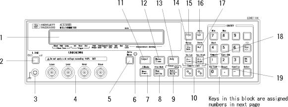
Front Panel
This section gives a guided tour of the HP 4338B's front panel.
For a detailed description of each key's function, see Chapter 3.
Each description starting with (Shift) is the secondary function of the key, which is available by pressing the BLUE shift key (see 32).
1.Display displays the measurement result, instrument states and messages. For more
information, see \Display".
2.LINE Switch turns the HP 4338B ON and OFF.
3.Chassis Terminal is connected to the instrument's chassis.
4.UNKNOWN Terminals are the test ports for test xtures and test leads. Connector type
is BNC.
5.Auto Measurement Key enables or disables the Auto measurement function.
6.Auto Measurement Indicator turns ON when Auto Measurement is enabled, and OFF
when disabled.
7.Measurement Parameter Key sets measurement parameter to be displayed. (Shift) Deviation Mode Key enables the deviation measurement function.
8.Show Setting Key changes the mode of Measurement Settings display. (Shift) Display Mode Key selects the display mode.
9.Auto/Hold Range Key selects the Auto or Hold range mode.
(Shift) Range Setup Key toggles the measurement range mode between Auto and Hold. 10. Left/Down Arrow Key and Right/Up Arrow Key increases or decreases setting value.
12.Measurement Time Key selects the measurement time, from Short, Medium, or Long. 13 Averaging Key sets the averaging rate used to average the measurement result.
13.Level Key selects the source output level.
1-4 Getting Started

HP 4338B |
Overview |
14.Trigger Mode Key selects the trigger mode.
(Shift) Delay Key selects the trigger source from Internal, Manual, or External.
15.Trigger Key triggers a measurement when in the Manual trigger mode.
16.Local Key returns the HP 4338B to the local mode from the HP-IB remote mode. (Shift)Address Key sets the HP 4338B's HP-IB address.
17.Recall Key recalls the instrument state data from HP 4338B's internal memory. (Shift) Save Key saves the instrument state data to the HP 4338B's internal memory.
18.Primary Comparator Upper Limit (Pri High) Key - sets the upper limit of the
comparator function for the primary comparator.
(Shift) Secondary Comparator Upper Limit (Sec High) Key - sets the upper limit of the comparator function for the secondary comparator.
19. Primary Comparator Lower Limit (Pri Low) Key - sets the lower limit of the comparator function for the primary comparator.
(Shift) Secondary Comparator Lower Limit (Sec Low) Key - sets the lower limit of the comparator function for the secondary comparator.
20. 0 Key / (Shift) Key Lock Key locks out all key input except for this key.
21. . Key / (Shift) Reset Key resets the HP 4338B to its default state.
22.0 Key / (Shift) Con guration Key sets the beep setting and power line frequency setting, and executes the internal test.
23.3 Key
24.2 Key / (Shift) Contact Check Key toggles
the contact check function between ON and OFF.
25.1 Key / (Shift) Comparator Key toggles
the comparator function between ON and OFF.
26.4 Key / (Shift) Short Key a SHORT correction measurement to get correction data.
27.5 Key
28.7 Key / (Shift) Minimum Key enters the minimum value when setting a parameter.
29.8 Key / (Shift) Maximum Key enters maximum value when setting a parameter.
30.6 Key
31.9 Key
32.BLUE Shift Key activates secondary functions printed above the front-panel keys.
Note |
In this manual, the BLUE shift key is expressed as |
, the top of the key is |
not labeled with \blue".
Getting Started 1-5
Overview |
HP 4338B |
33.Engineering Unit Key enters the engineering units, p, n, , m, k, and M.
34.Back Space Key erases the last entered character when entering numeric values.
35.Enter Key terminates key entry.
1-6 Getting Started

HP 4338B |
Overview |
Display
This section introduces the display. For a detailed description of each display eld, see Chapter 3.
1. Character Display Area displays the measurement result, setting data, and instrument messages.
2. Annunciator (9 ) points to the currently selected instrument setting. The label pointed to by the annunciator is the current setting. The annunciator labels are as follows:
a.Measurement time shows the selected measurement time, Short, Medium or Long.
b.Trigger indicates that the trigger mode is Internal, Manual, or External.
c.Hold Range indicates that the HP 4338B is in the Hold range mode. When in the Auto
range mode, the Hold range annunciator is not displayed.
indicates that the HP 4338B is in the Hold level mode. When in the Auto level mode, the Hold level annunciator is not displayed.
e.Comparator On indicates that comparator function is ON.
f.Contact Check On indicates that the contact check function is ON.
g.Talk Only indicates that the HP 4338B is in the HP-IB talk only mode.
h.Remote indicates that the HP 4338B is in the HP-IB remote mode.
i.Key Lock indicates that the HP 4338B's front panel keys are locked out.
j.Measurement Setting Shows the HP 4338B's settings such as test signal level, averaging
rate, etc.
k. Shift annunciates that the shift toggle is active.
Getting Started 1-7
Overview |
HP 4338B |
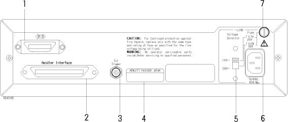
Rear Panel
This section gives a guided tour of the rear panel. For a detailed description of each item, see Chapter 3.
1. HP-IB Interface is used to control the HP 4338B from an external controller by using the HP-IB bus.
2.HANDLER Interface is used to synchronize timing with an external handler.
3.EXT TRIGGER Terminal is used to input an external trigger signal.
4.Serial Number Plate gives the instrument's manufacturing information.
5.Line Voltage Selector used to set the HP 4338B's line voltage setting to the voltage of the
ac power source.
6.Power Cord Receptacle
7.LINE Fuse Holder
1-8 Getting Started

HP 4338B |
Overview |
|
|
Incoming Inspection |
|
|
|
Warning |
To avoid hazardous electrical shock, do not turn on the HP 4338B when |
|
there are signs of shipping damage to any portion of the outer enclosure |
(for example, covers, panel, or display)
Inspect the shipping container for damage. If the shipping container or cushioning material is damaged, it should be kept until the contents of the shipment have been checked for
completeness and the HP 4338B has been checked mechanically and electrically. The contents of the shipment are as follows:
HP 4338B LCR Meter
Power Cable
Operation Manual(This Book)
User's Guide
If the contents are incomplete, if there is mechanical damage or defect, or if the analyzer does not pass the power-on selftests, notify the nearest Hewlett-Packard o ce. If the shipping container is damaged, or the cushioning material shows signs of unusual stress, notify the carrier as well as the Hewlett-Packard o ce. Keep the shipping materials for the carrier's inspection.
Ventilation Requirements
To ensure adequate ventilation, make sure that there is adequate clearance of at least 400 mm behind, 100 mm sides and 15 mm above.
Instruction for Cleaning
For cleaning, wipe with soft cloth that is soaked with water and wrung tightly without undue pressure.
Getting Started 1-9

Overview |
HP 4338B |
Power Cable
In accordance with international safety standards, this instrument is equipped with a three-wire power cable. When connected to an appropriate ac power outlet, this cable grounds the instrument frame. The type of power cable shipped with each instrument depends on the country of destination. Refer to Figure 1-1 for the part numbers of the power cables available.
Warning |
For protection from electrical shock, the power cable ground must not be |
|
defeated. The power plug must be plugged into an outlet that provides a |
|
protective earth ground connection. |
|
|
1-10 Getting Started

HP 4338B |
Overview |
Figure 1-1. Power Cable Supplied
Getting Started 1-11
 Loading...